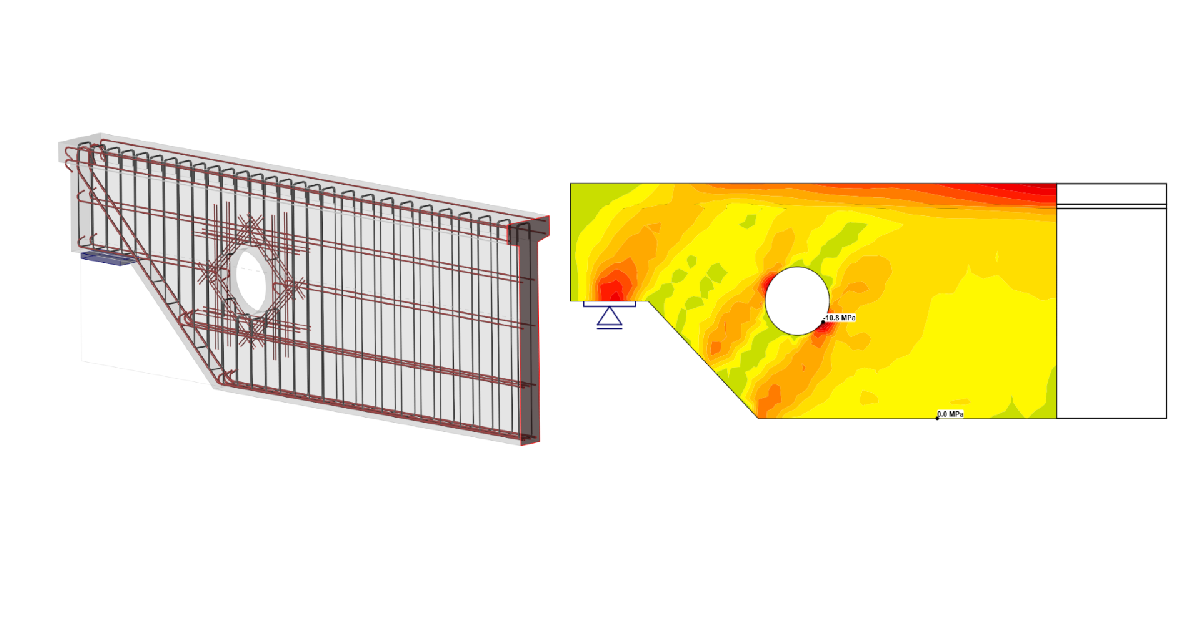
Structural design of a dapped end with an opening (EN)
1 New project
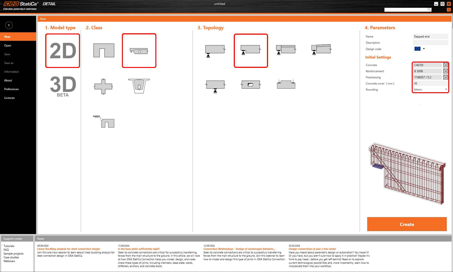
Start by launching IDEA StatiCa and select the application Detail. Create a new project you can start with a selection of proper concrete grade C40/50 and cover 30 mm. Then continue with Members 2D topology. In Members 2D templates, select Dapped end, one css.
After this, a predefined template will load geometry and basic reinforcement into our model.
2 Geometry
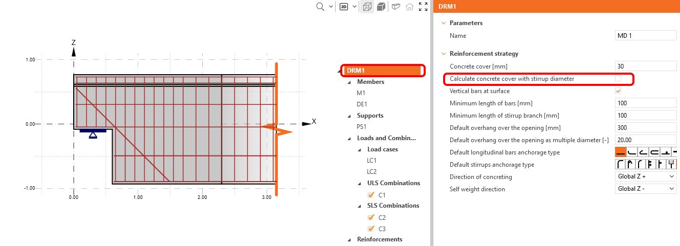
In this example, please ensure to uncheck the checkbox for calculating the concrete cover with the stirrup diameter.
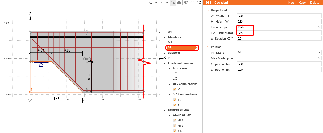
Start with the modification of geometry. Three items have been loaded by the template: Member M1 dapped end DE1, and point support PS1. We click on DE1 and choose right-sided haunch with 0.85 m width.
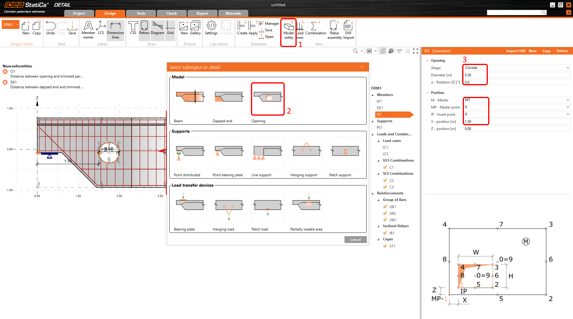
Continue with the addition of an opening. To add it, click on the Model entity button, and in Model pick Opening.
Change the shape of the opening to Circular and the diameter to 0.5 m. To place the opening to the desired position, use the master and insert points relationship. The master component will be M1 and masterpoint no. 8, insert the point of opening also no. 8, and the distance between these points in X direction will be 1.5 m.
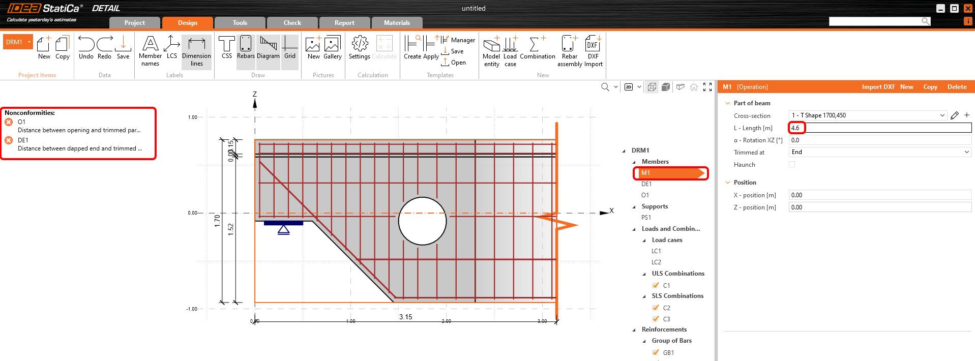
IDEA StatiCa Detail warns you by error messages, that the length of the detail is insufficient. The trimmed end of detail should be at a distance of at least 1.5*h from the last source of discontinuity. In this case, the governing source is opening and the sufficient length of the member is 4.6 m. All warnings should disappear after the elongation of member M1.
3 Loads
Two load cases and three nonlinear combinations were automatically added by the software. You need two load cases to distinguish between permanent and variable loads and three combinations to cover one ULS and two SLS combinations (Characteristic and Quasi-permanent) for all checks.
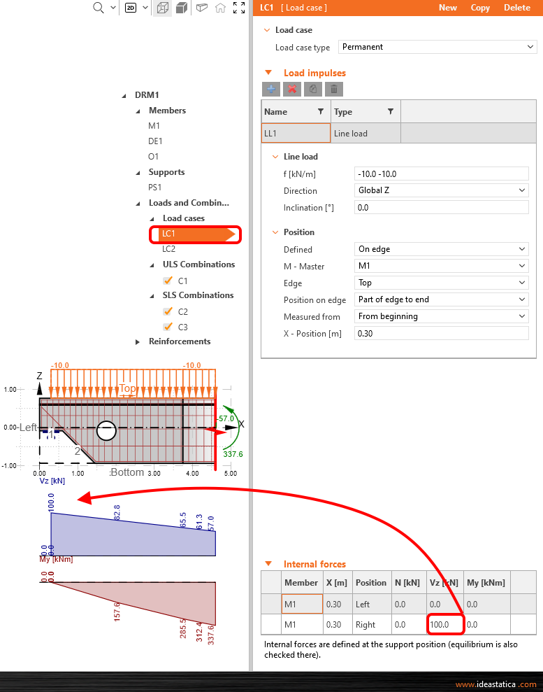
Modify load case LC1 for permanent effects. Apply reaction as a shear force 100 kN Vz from the right position. You can see the change in the internal forces diagram.
Switch to LC2 load case by combo box and repeat the steps with 120 kN Vz values.
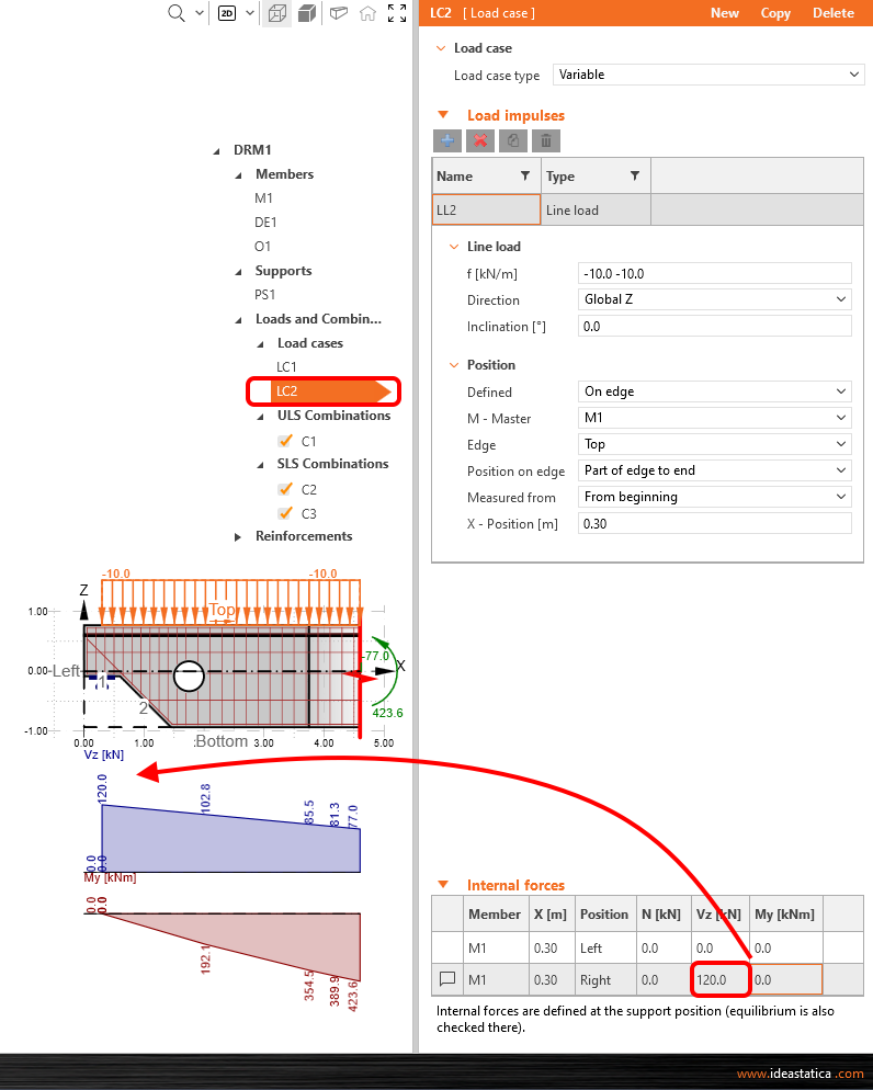
As you want to decrease the values of internal forces at the trimmed end, in LC 2 change the line load value to -12 kN/m.
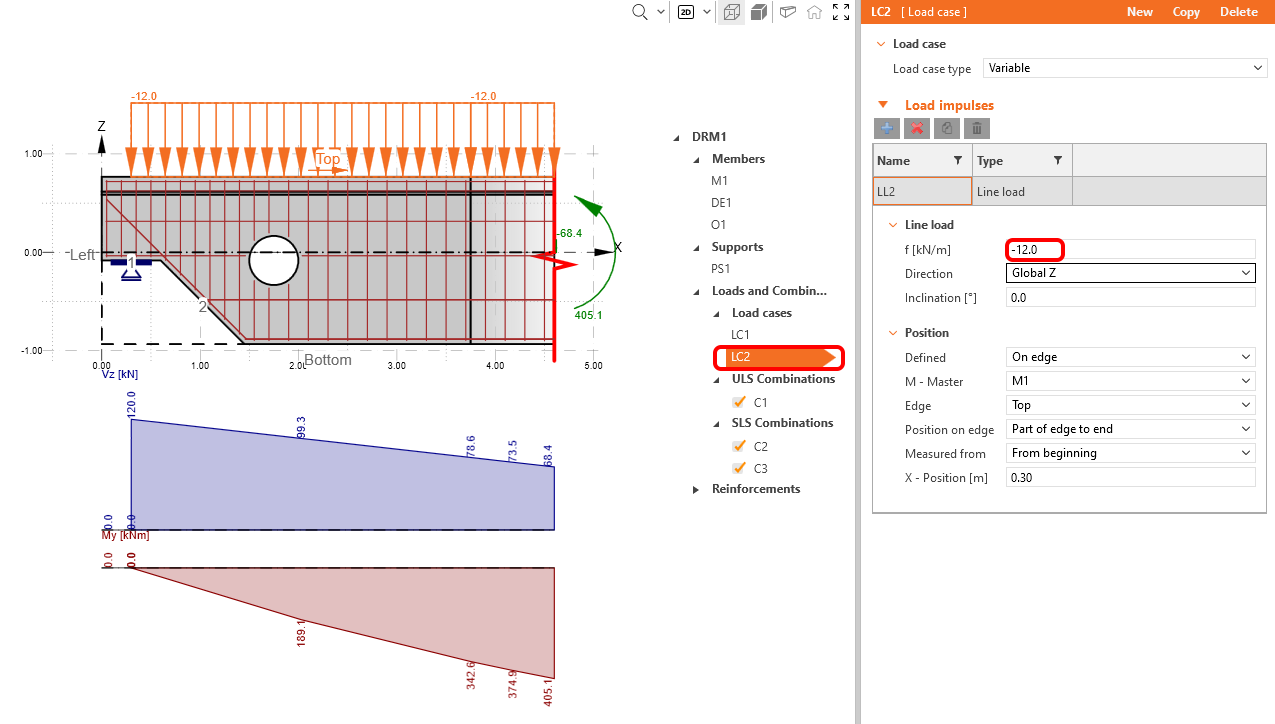
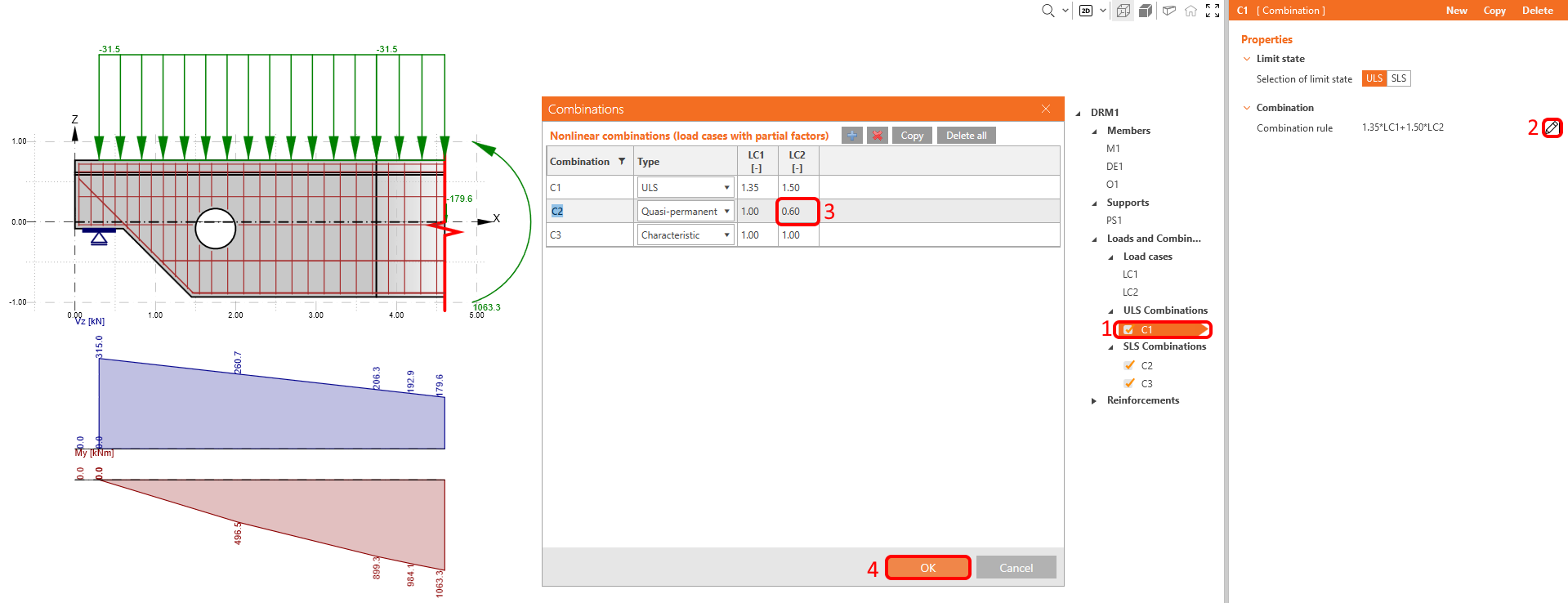
The last step in loads definition will be the change of the partial factor for quasi-permanent combination CO2 . You can access the partial factor dialog from any defined combination by the pen icon next to the combination rule. Change the LC2 partial factor to 0.60.
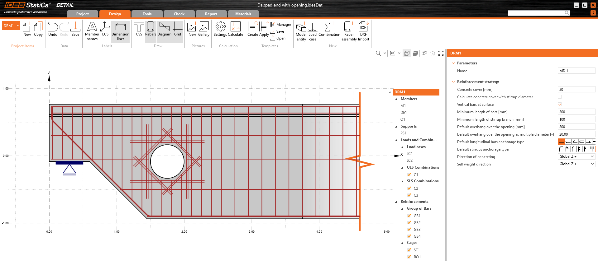
4 Reinforcement
To reinforce this particular model, start with a predefined template in IDEA StatiCa Detail and modify it. Before doing that, you would like to see, how to reinforce it based on design tools results.
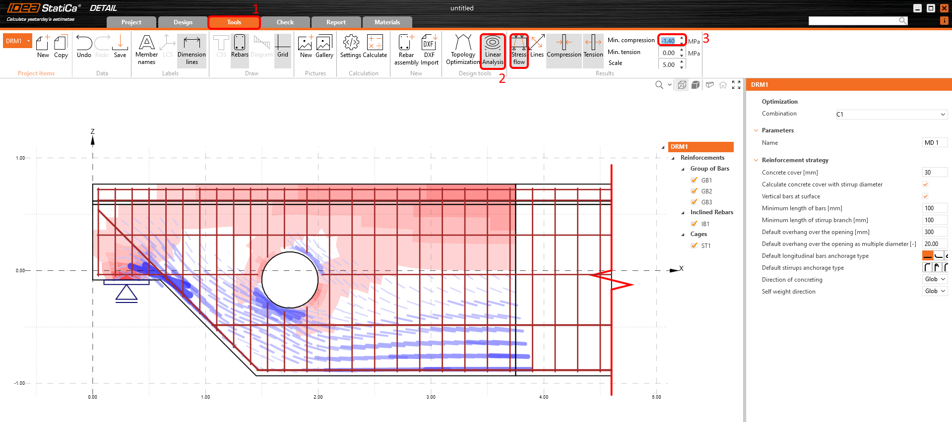
Click on the Linear analysis icon to run it. To see the most compressed fields better, you can apply a filter for compression -1.4 MPa on the right side of the ribbon. Red areas represent compression, and blue lines show tension. These are the results you can see:
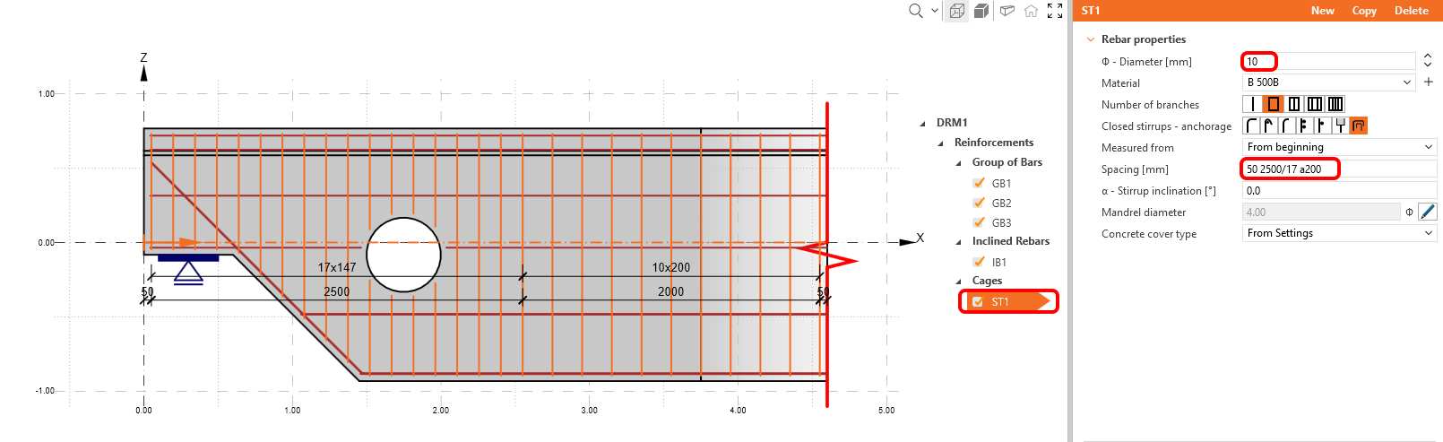
First item ST1 is used for stirrups modeling. Modify the diameter of the stirrups to 10 mm and change the distances between stirrups as 50 2500/17 a200. As you can see, you can combine several definitions of distances. This means, that first stirrup is positioned 50 mm from edge, then we fill 2.5 m by a division of 17 and fill the rest per 200 mm distance.
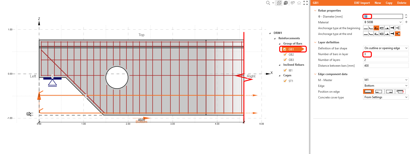
Change reinforcement item GB1 properties.
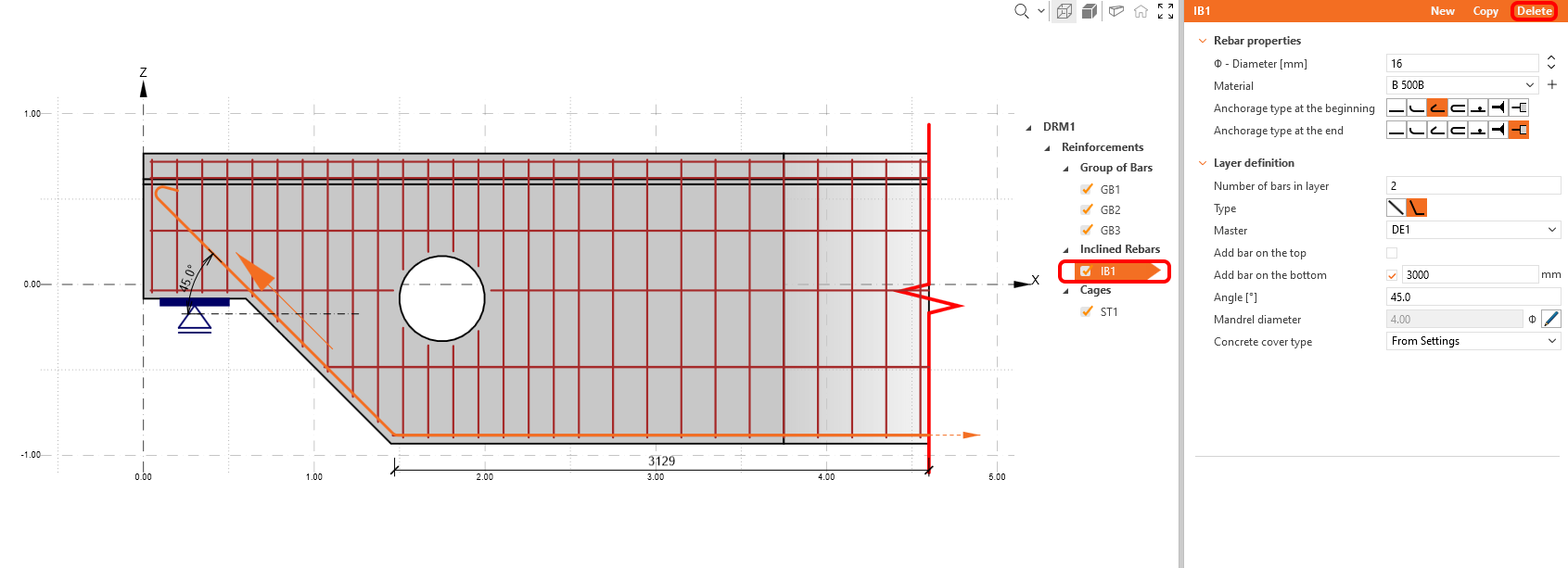
Replace reinforcement item IB1 by another group of bars item – delete IB1 first.
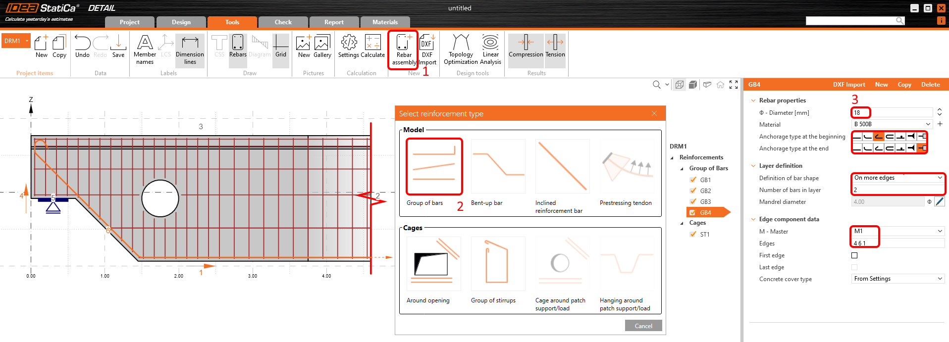
To add a new reinforcement item, use the Model entity button and select the Group of bars.
Change the definition of GB4 bar shape to On more edges and then adjust the diameter. Then fill in the right order of edges to place the rebar into the desired position.
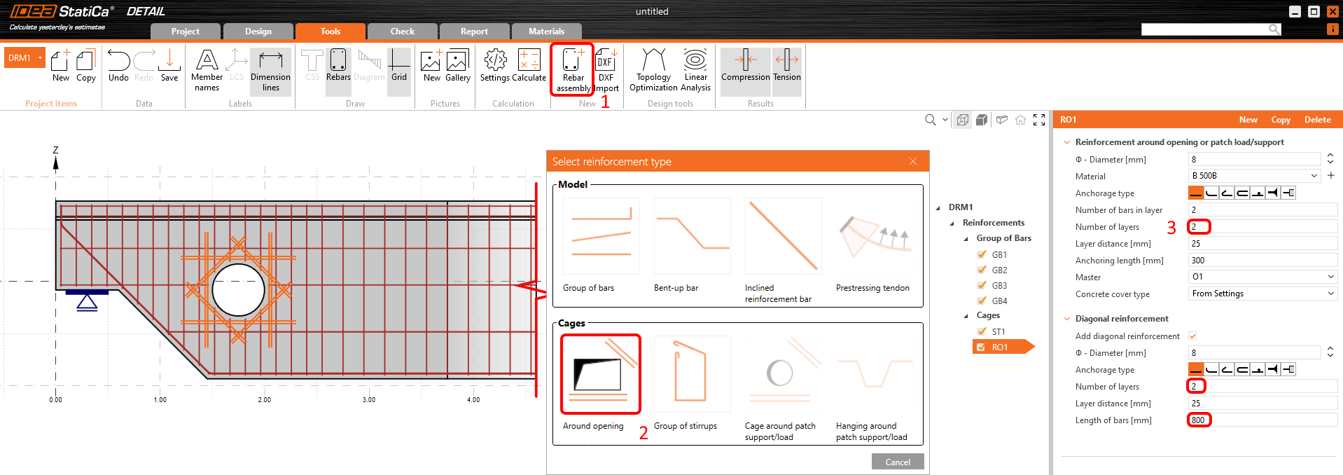
You added the opening to the original template and thus you need to add reinforcement around it. Again, press Model entity button and in Cages we select Around opening.
Modify its properties according to the screenshot.
This is how your final reinforcement should look like:
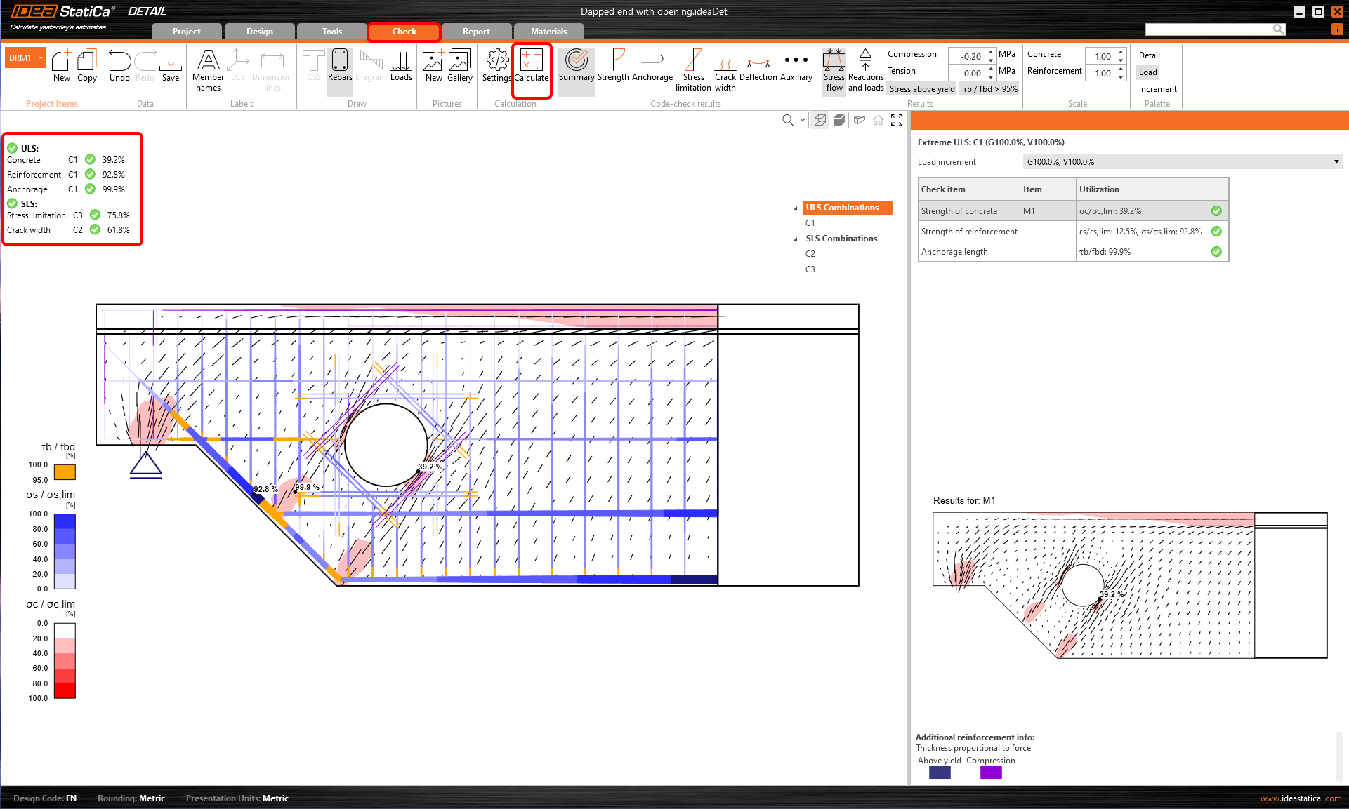
5 Calculation and Check
Start the analysis by clicking Calculate in the ribbon. The analysis model is automatically generated, the calculations are performed and you can see the summary of checks displayed together with the values of check results.
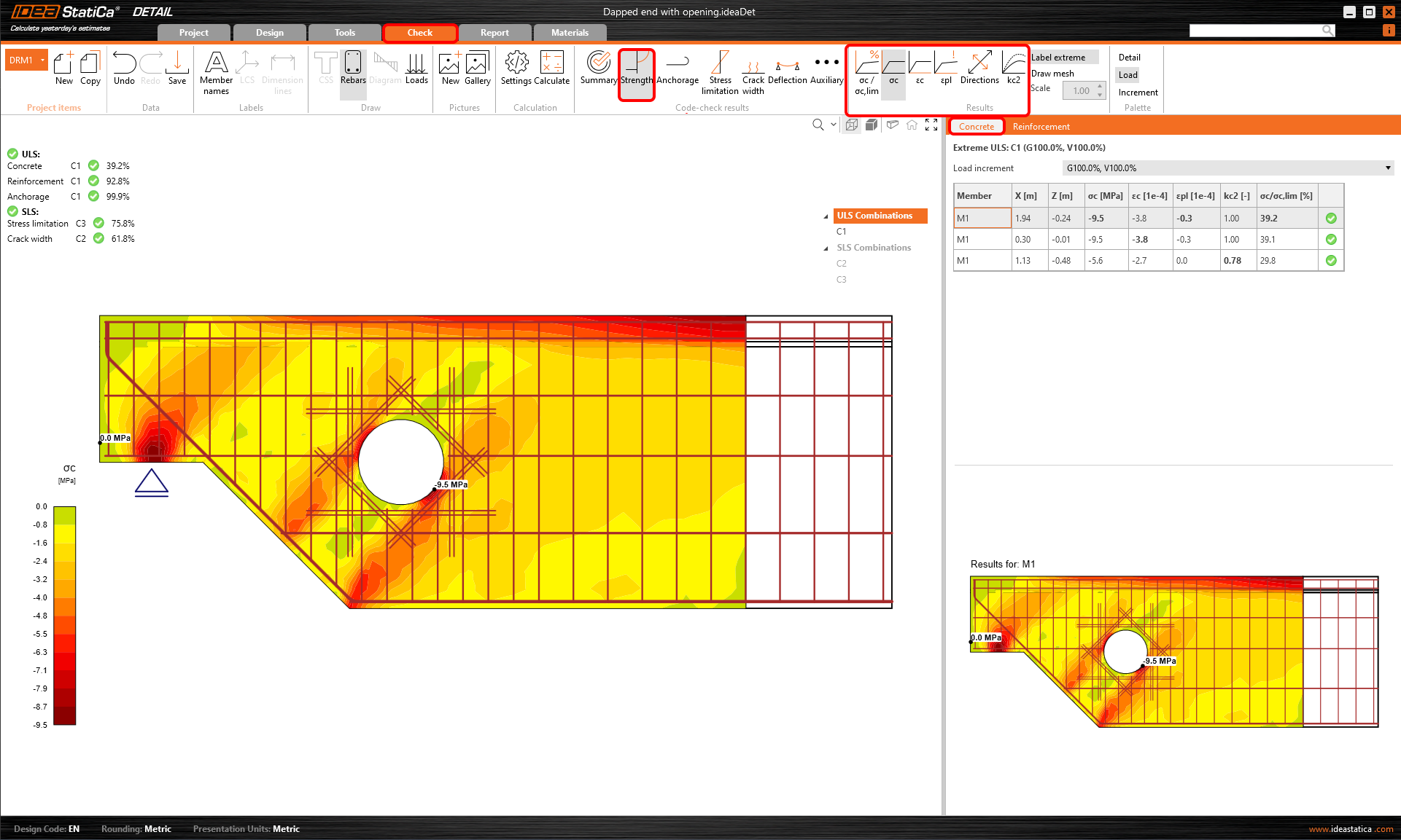
To go through detailed checks of each component, start with the Strength tab. This will show concrete checks such as utilization in stress, principal stresses, strains, and a map of reduction factor kc which can be switched on the ribbon.
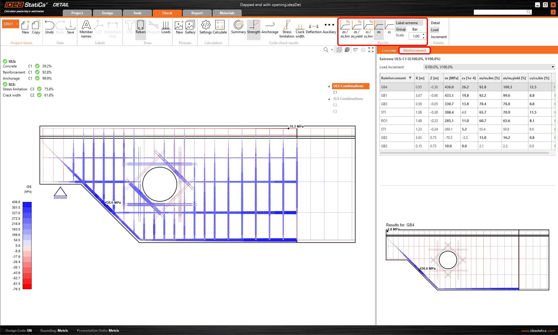
For detailed reinforcement results, click on a row, Reinforcement. This will change the ribbon icons and unroll the table for results. We can display results for strains and stresses in each bar and their utilization.
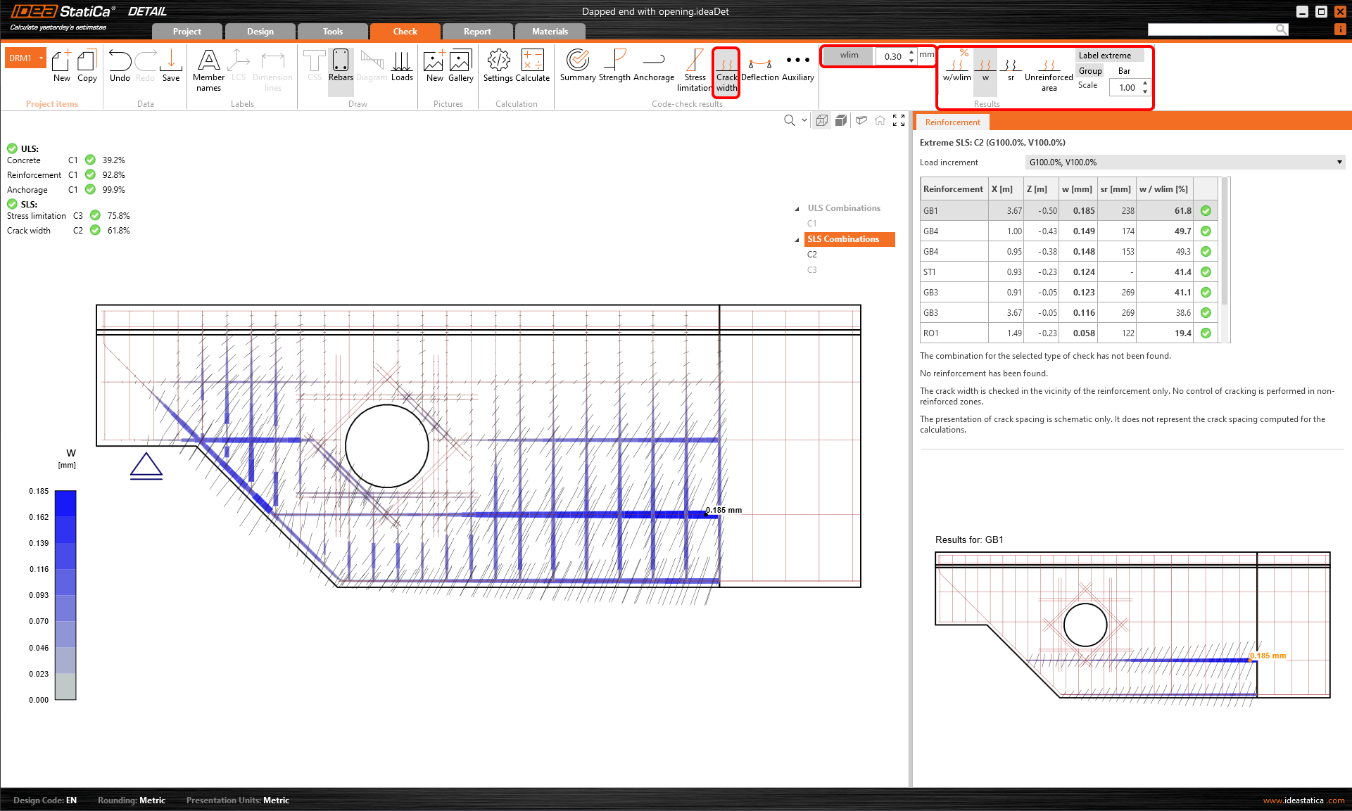
All results can be displayed in the same way. Let´s show the difference in ribbon for SLS checks crack-width and deflection. Besides the icons to switch between the results, there are settings in the ribbon to set the limit value or display of results from short/long-term models.
6 Report
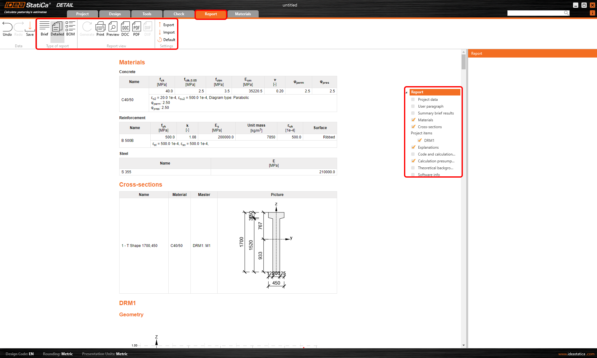
At last, go to the Report. IDEA StatiCa offers a fully customizable report to print out or save in an editable format.
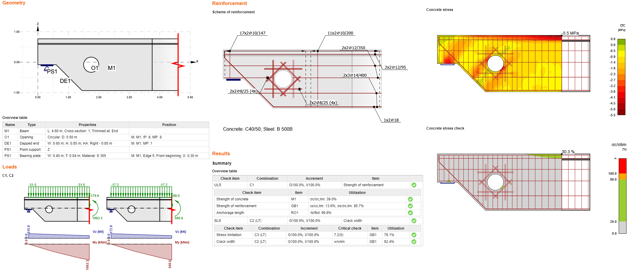
You have designed, optimized, and code-checked a dapped end with an opening according to Eurocode.