Idea Statica
  • Steel
  • Concrete
  • BIM & workflows
  • Support & Learning
  • Pricing
  • Company
  • Steel overview
  • Connection design
  • Member design
  • Parametric design
  • Steel case studies
  • Concrete overview
  • Walls and D-regions
  • Anchoring design
  • Members & cross-sections
  • Concrete case studies
  • BIM overview
  • Supported integrations
  • Checkbot
  • Viewer
  • APIs
  • Support Center
  • E-learning & certification
  • Blog
  • Downloads & Licensing
  • Plans
  • Free community tool
  • Enterprise customers
  • Students & educators
  • How much will you save?
  • About us
  • Contact
  • Research & development
  • Authorized resellers
  • Meet our customers
  • Career
  • Steel
    Steel overviewConnection designMember designParametric designSteel case studies
  • Concrete
    Concrete overviewWalls and D-regionsAnchoring designMembers & cross-sectionsConcrete case studies
  • BIM & workflows
    BIM overviewSupported integrationsCheckbotViewerAPIs
  • Support & Learning
    Support CenterE-learning & certificationBlogDownloads & Licensing
  • Pricing
    PlansFree community toolEnterprise customersStudents & educatorsHow much will you save?
  • Company
    About usContactResearch & developmentAuthorized resellersMeet our customersCareer
14-Day Trial
14-Day Trial
  • Steel
  • Concrete
  • BIM & workflows
  • Support & Learning
  • Pricing
  • Company

Subscribe to our newsletter

Company

  • About us
  • Partners
  • Careers
  • Patent

Resources

  • Customer projects
  • Case studies
  • Connection Library
  • Verification books

Legal

  • EULA
  • Privacy policy
  • California Privacy
  • TOS Viewer
  • Licensing

Help

  • Contact
  • Quote request
  • Resellers
  • Downloads
FacebookInstagramLinkedInYouTube

© IDEA StatiCa 2009-2026

Trusted and used worldwide by engineers, fabricators & consultants.

Support CenterKnowledge Base ArticlesStress-strain diagrams in CSFM
IDEA StatiCa Detail – Structural design of concrete discontinuities
Basic assumptions of Compatible Stress Field Method (CSFM)
CSFM explained
CSFM Book – Compatible stress field design of structural concrete
Bond model for SLS (Detail)
Stress-strain diagrams in CSFM
Stress-strain diagram of concrete and reinforcement
ConcreteReinforced concretePrestressed concreteKnowledge baseACI (USA)

Stress-strain diagrams in CSFM

This article is also available in
ENCZDEESFRITPTNLHUROKRPLTHTRVIZH

The materials used and their characteristics are the basic parameters for a correct code-check. Let's see what stress-strain diagrams are used in IDEA StatiCa Detail and also how the elastic modulus E in ULS and SLS are calculated.

In the first part of the article, we will focus on the stress-strain diagrams themselves:

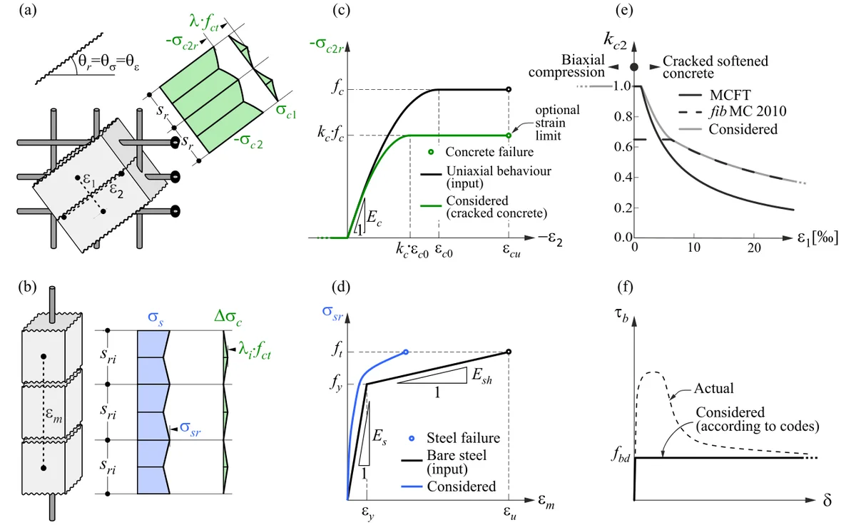
Stress-strain diagrams implemented in CSFM are based on code requirements, both Eurocode (EN) and ACI. When dealing with concrete, it is necessary to distinguish between ULS and SLS assessments. 

A concrete member in the ultimate limit state (ULS) is based on the parabolic-rectangular diagram (EN) or bilinear one (ACI), including the compression softening effect. For serviceability assessments, a different, simpler diagram is used, a linear or bi-linear diagram with an infinite elastic branch. 

Bilinear diagrams with an inclined or horizontal top branch are considered for reinforcement, including tension stiffening effects for both ULS and SLS checks.

Check the video below, where all stress-strain diagrams are displayed and briefly described.  A more detailed description of stress-strain relationships is explained in the theoretical background.

Now when it is clear what diagrams are used. Let's see how the Elastic module E is calculated:

ULS

Elastic modulus is calculated from concrete stress value at specific age (introduce concrete compressive strength growth with age) and strain value at maximal strength values.

The following table shows the growth of elastic modulus over time in the last column, where after the age of 28 days, the maximal value of 10GPa is reached.

SLS

The code considers Ecm value set for 0,4fcm as secant elastic modulus in chapter 3.1.3.

In paragraph (3) it states:

The following table shows the growth of elastic modulus considered for characteristic combination (SLS):

The type of aggregate also changes the calculation of elastic modulus. The aggregate type used in concrete is set for Quarzite as a default value. The reduction of modulus is considered for limestone or sandstone aggregate, and for basalt aggregate, it applies the increase of elastic modulus.
Related articles

Basic assumptions of Compatible stress field method (CSFM)
  • Concrete
  • ACI (USA)
  • EN (Eurocode)
  • CSFM
  • Cracks
  • Stress in reinforcement
  • Detail 2D
  • +7
  • Concrete
  • ACI (USA)
  • EN (Eurocode)
  • CSFM
  • Cracks
  • Stress in reinforcement
  • Detail 2D

Knowledge base

Basic assumptions of Compatible Stress Field Method (CSFM)

Read more
IDEA StatiCa Detail is concrete design software for the structural design and code-check of concrete discontinuity regions. Concrete members stress analysis & concrete wall design.
  • Concrete
  • ACI (USA)
  • EN (Eurocode)
  • Geometry
  • Load effects
  • Overall check
  • Material settings
  • Corbels/Brackets
  • CSFM
  • Cracks
  • Deflections
  • Diaphragms
  • Openings
  • SLS
  • Stress in reinforcement
  • TDA
  • Topology optimization
  • ULS
  • Detail 2D
  • +19
  • Concrete
  • ACI (USA)
  • EN (Eurocode)
  • Geometry
  • Load effects
  • Overall check
  • Material settings
  • Corbels/Brackets
  • CSFM
  • Cracks
  • Deflections
  • Diaphragms
  • Openings
  • SLS
  • Stress in reinforcement
  • TDA
  • Topology optimization
  • ULS
  • Detail 2D

Theoretical background

IDEA StatiCa Detail – Structural design of concrete discontinuities

Read more
What are the key differences between the methods CSFM and S&T
  • Concrete
  • ACI (USA)
  • Detail 2D
  • CSFM
  • EN (Eurocode)
  • +5
  • Concrete
  • ACI (USA)
  • Detail 2D
  • CSFM
  • EN (Eurocode)

FAQ

What are the key differences between the methods CSFM and Strut&Tie

Read more