Structural design of a concrete beam with an opening (EN)
1 New project
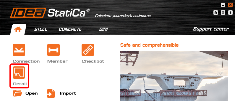
Start a New project in IDEA StatiCa Detail.
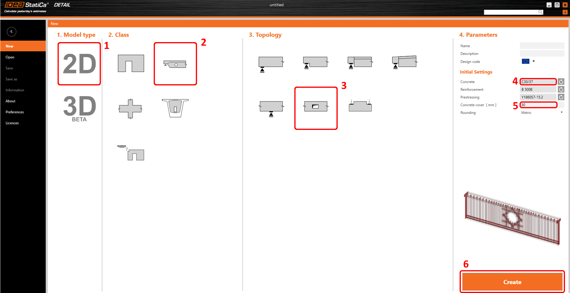
In the first step, select the desired class and topology, you can then define the design code (choose EN) as well as the concrete grade and cover (use concrete C30/37 and cover 30 mm). You can change your choice of material (or add another one) later, nevertheless, the design code can be chosen only in this first step of the project.
2 Geometry
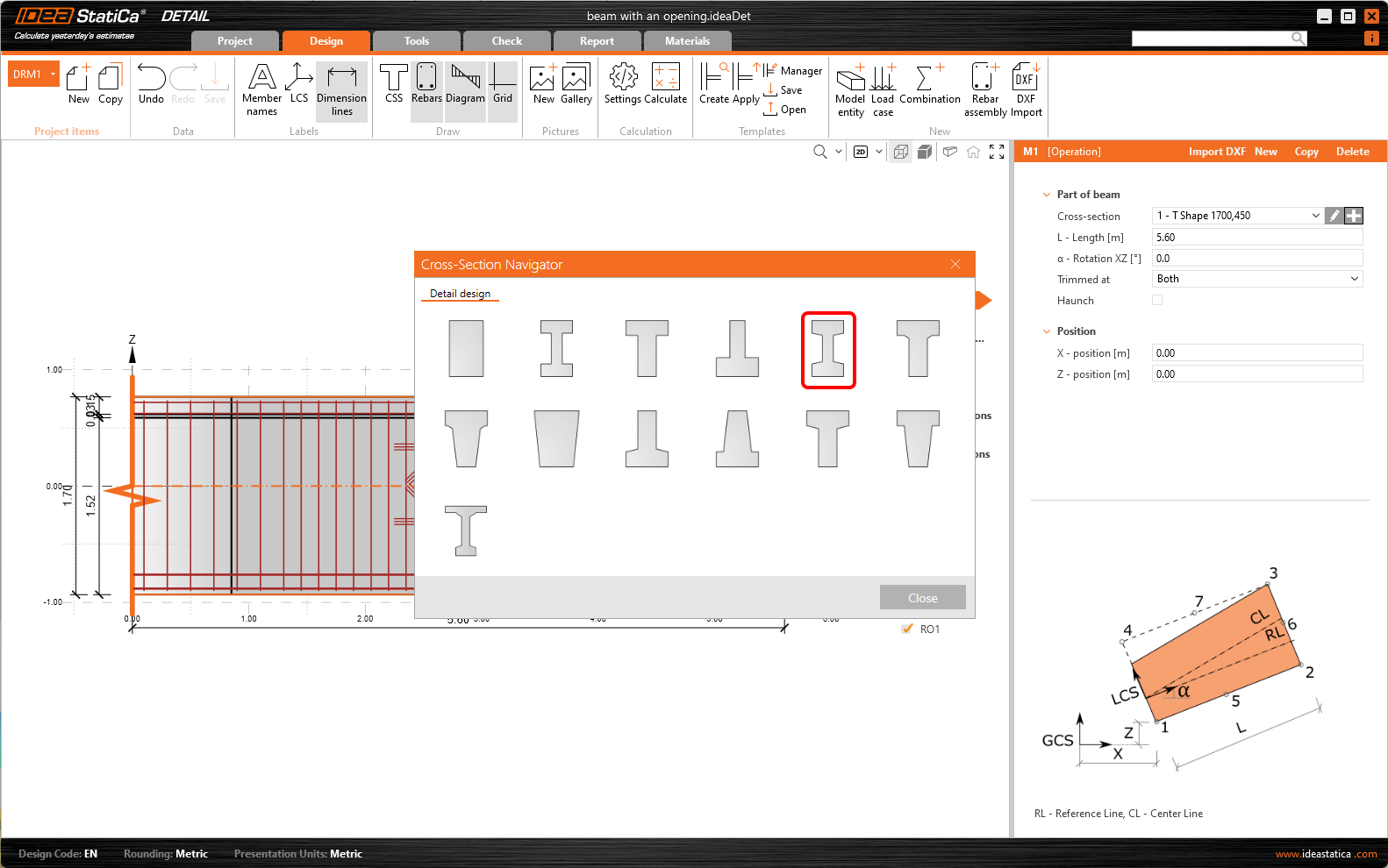
Start the definition of geometry by changing the cross-section of the Member M1.
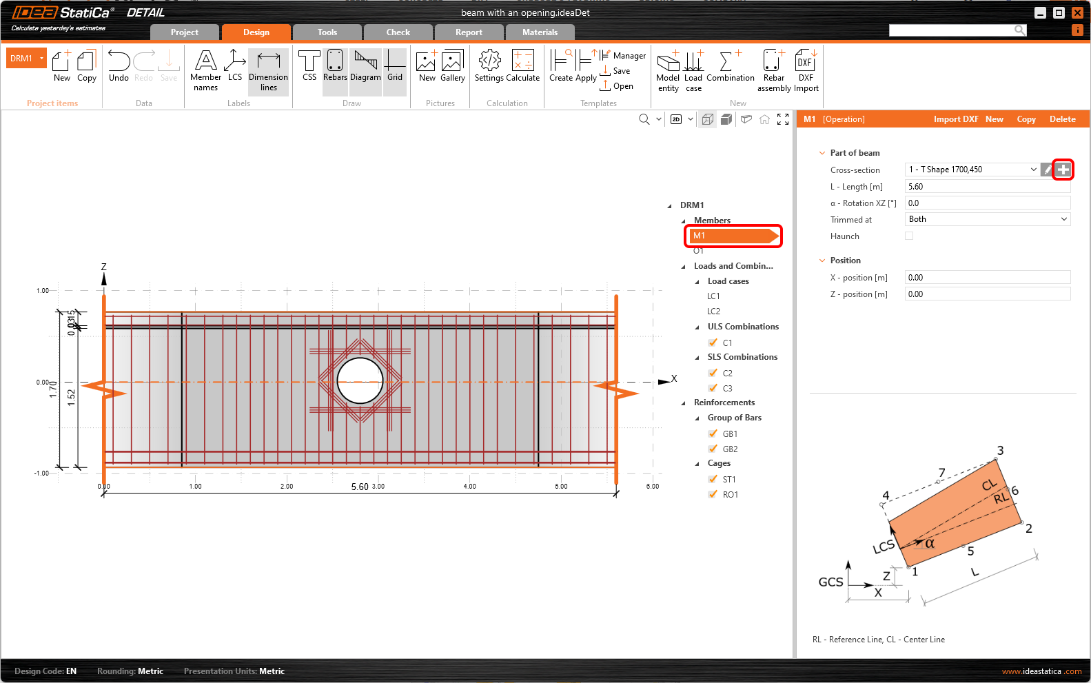
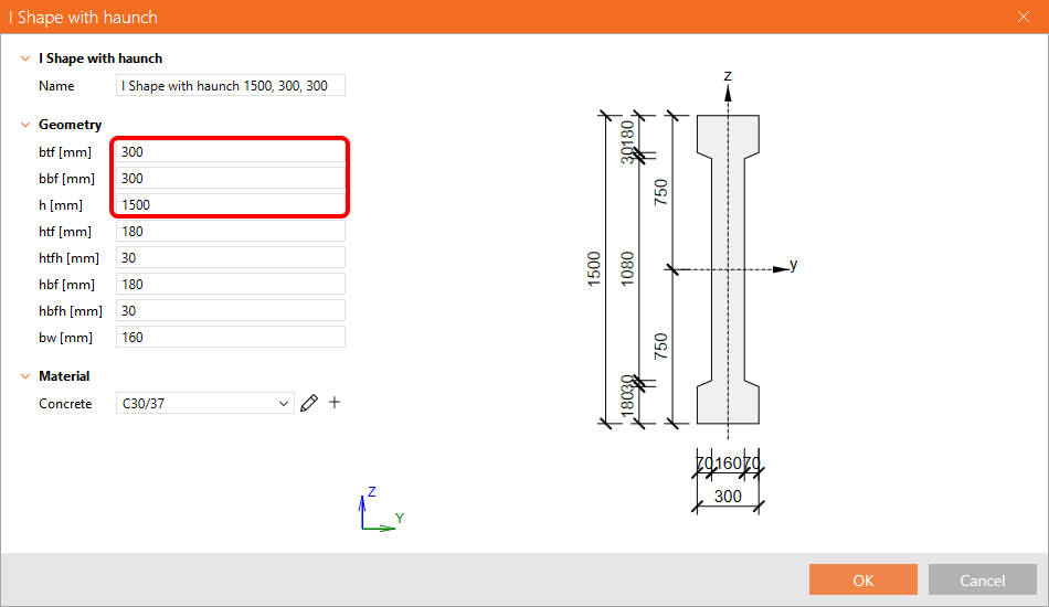
Define the I shape with haunched flanges.
Change the width of the flanges and the height of the beam.
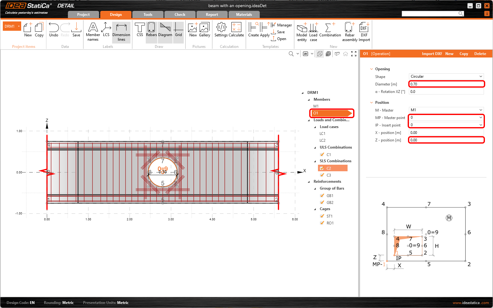
The opening is enlarged and shifted to the center of the beam.
- Read more about the geometry definition in Geometry types in Detail
3 Load effects
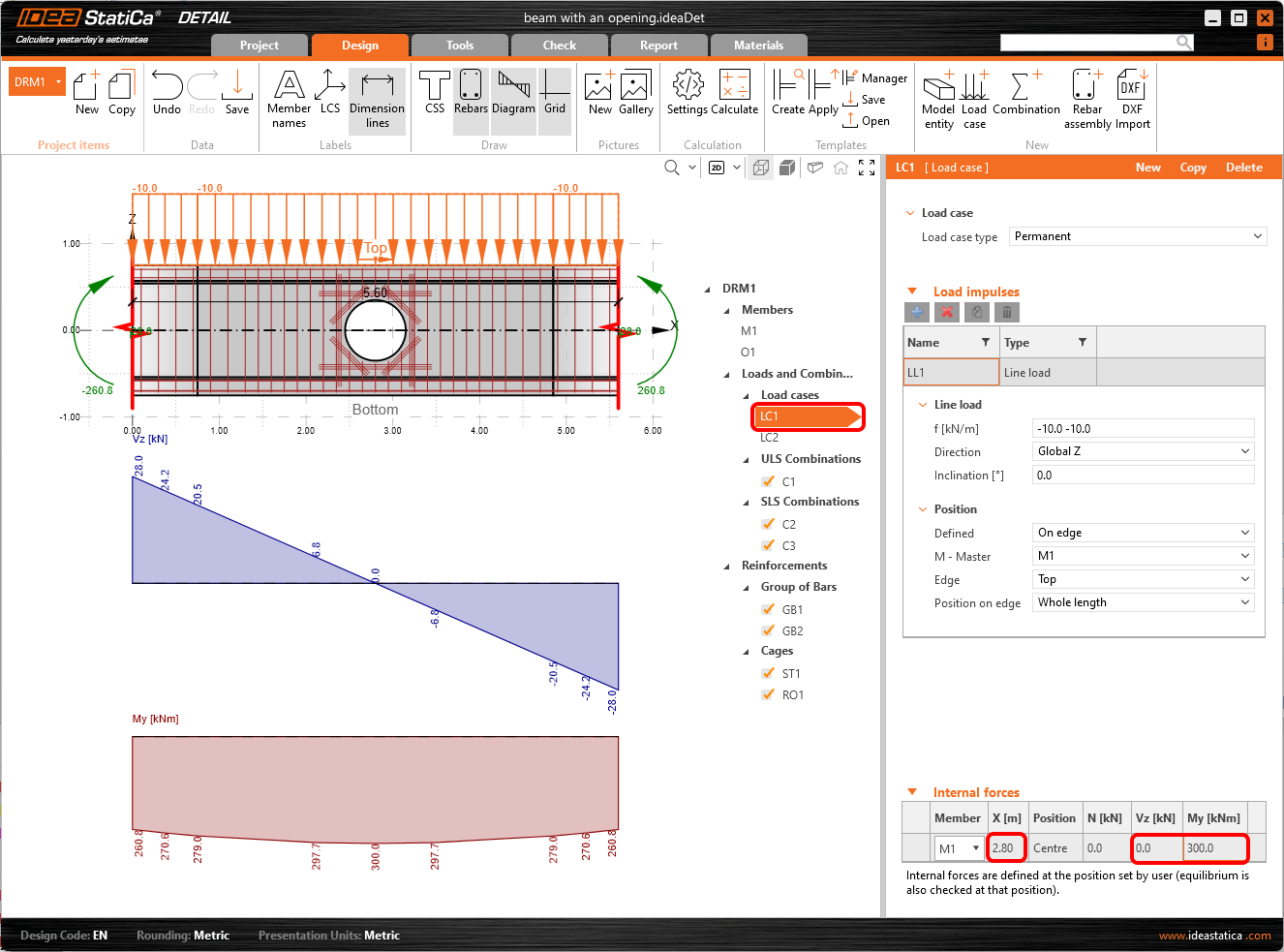
Let us now define the Load of the detail. You can see that two load cases were already automatically created. Change the content of the load cases a little bit.
For LC1 (permanent load), change the Internal forces so that you input the values of shear force and bending moment at the point of the opening. In Load Impulses, keep the value of line load to -10 kN/m in global Z-.
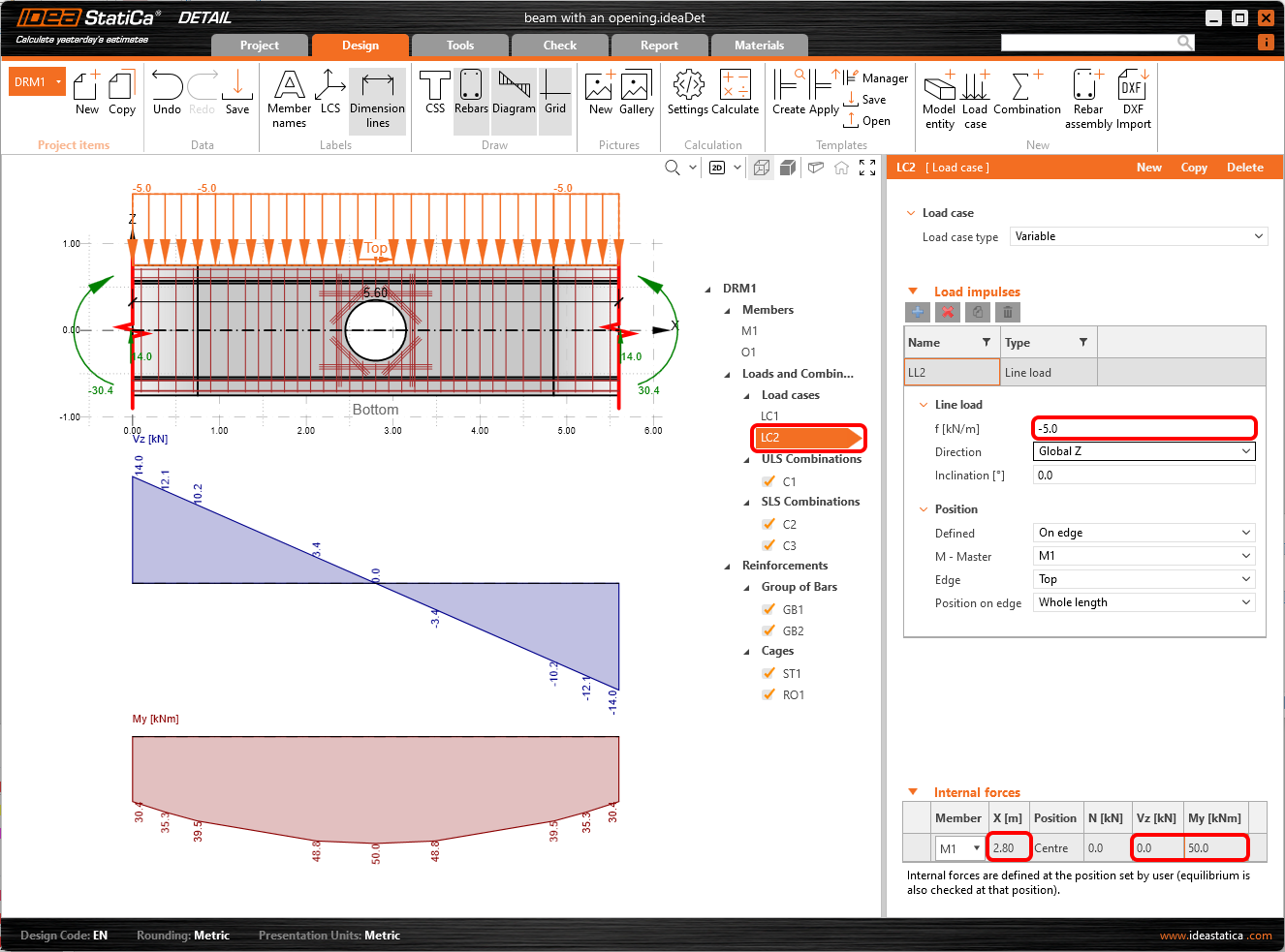
Similarly, change the values of Internal forces for LC2 (variable load). In Load impulses, change the value to -5 kN/m in global Z-direction.
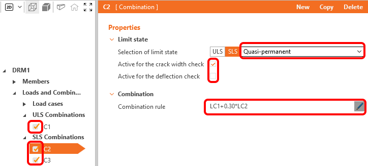
Three nonlinear combinations were already defined: C1 stands for ULS checks. C2 is a quasi-permanent and C3 a characteristic load combination, both defined for SLS code checks. You can define new combinations if required, there are three types of combinations available for SLS code checks: characteristic, frequent and quasi-permanent. You can select which checks shall be performed for each combination and the partial coefficients for the combination rules can be adjusted as well. In our case we use the predefined combinations.
The calculations will be performed only for the checked items. Right now we leave all three combinations (C1, C2 and C3) selected.
- Learn more about internal forces in General description of Load impulses in Detail application
- Learn more about load impulses in Internal forces and equilibrium in Detail application
4 Reinforcement
Once the load has been defined, you can proceed to input the Reinforcement. You will use the items created by the template.
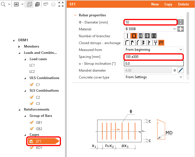
You can change the diameter of stirrups and adjust their distances (the first value corresponds to the distance of the first stirrup from the edge, the other stirrups will be distributed in distances given by the second value).
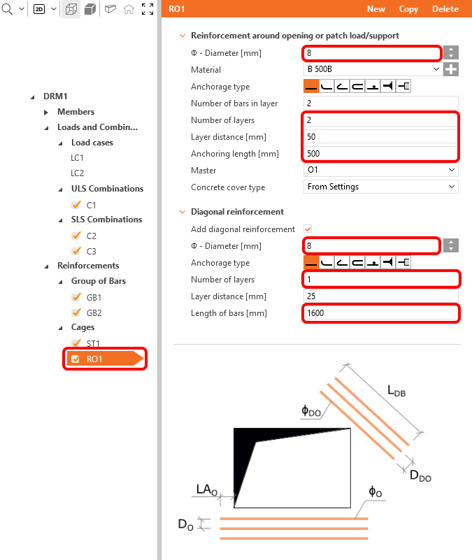
Reduce the diameter of bars of reinforcement RO1 around the opening and the number of layers of horizontal/vertical and diagonal bars. Change the distance between horizontal/vertical bars and also adjust the length of the diagonal bars and anchoring of horizontal/vertical bars.
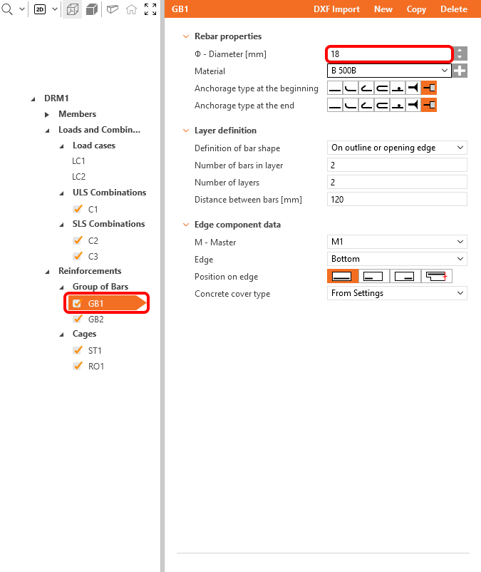
The operation GB1 includes a group of bars at the bottom face of the beam. Change the diameter of bars.
- Master your reinforcing skills by reading Reinforcement definition in the Detail application
5 Calculation and Check
Proceed to calculate the project. Continue to Check Tab and press the Calculate button in the top ribbon.
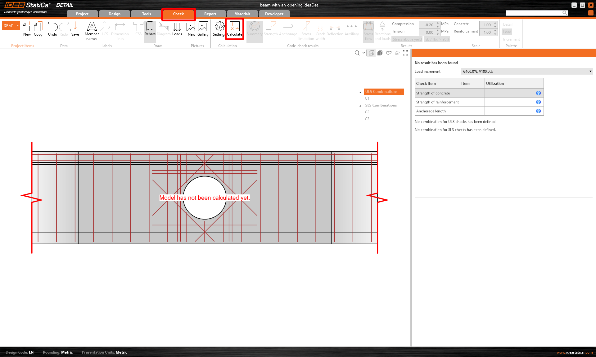
At the top left of the screen, you can see the overview of all the code checks and the status of the checks (passed/failed).
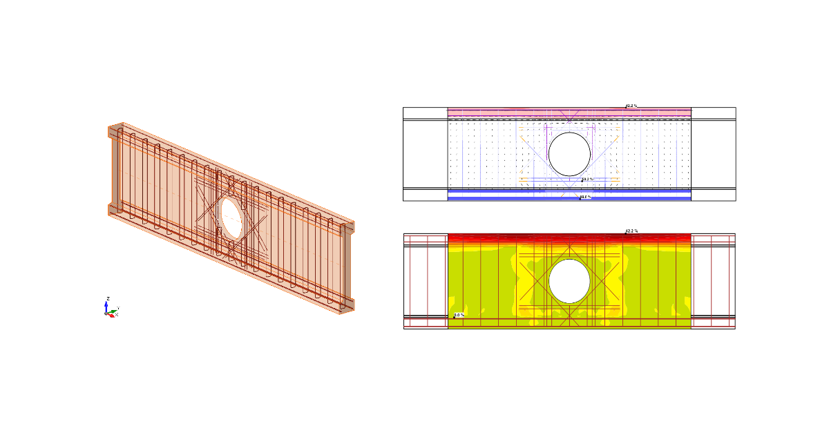
In the table on the right, all the detailed results and the amount of permanent and variable load applied can be found. At the moment, the resulting strength check of the concrete in ULS is presented. In the Results toolbar, the limit value for the diagram can be changed. Change the value so that only the concrete in compression over -2 MPa is marked red.
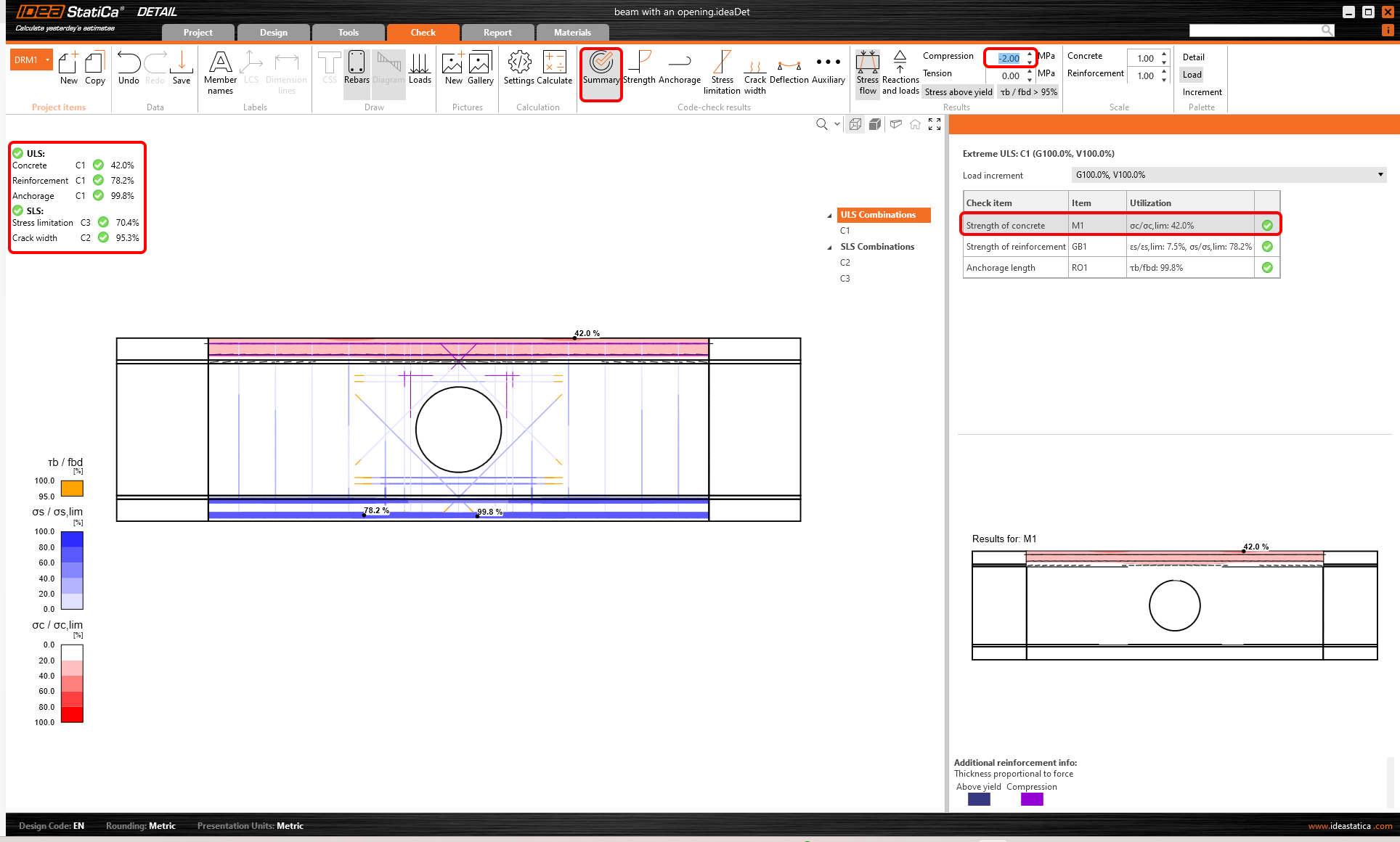
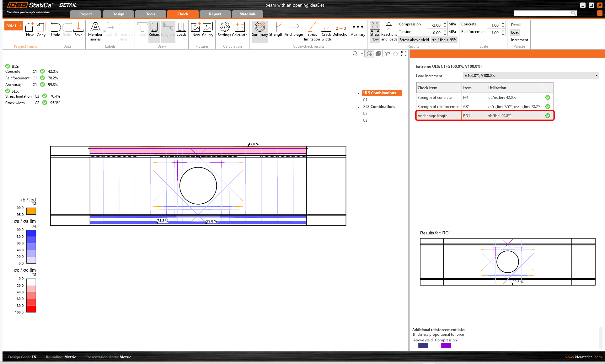
You can display all the code checks using the buttons in the Code-check results toolbar. In the Summary, the main results for ULS/SLS are presented. Click for instance on the line in ULS/Anchorage length to display the utilization of the bond between concrete and reinforcement (with the most critical spot marked in the figure).
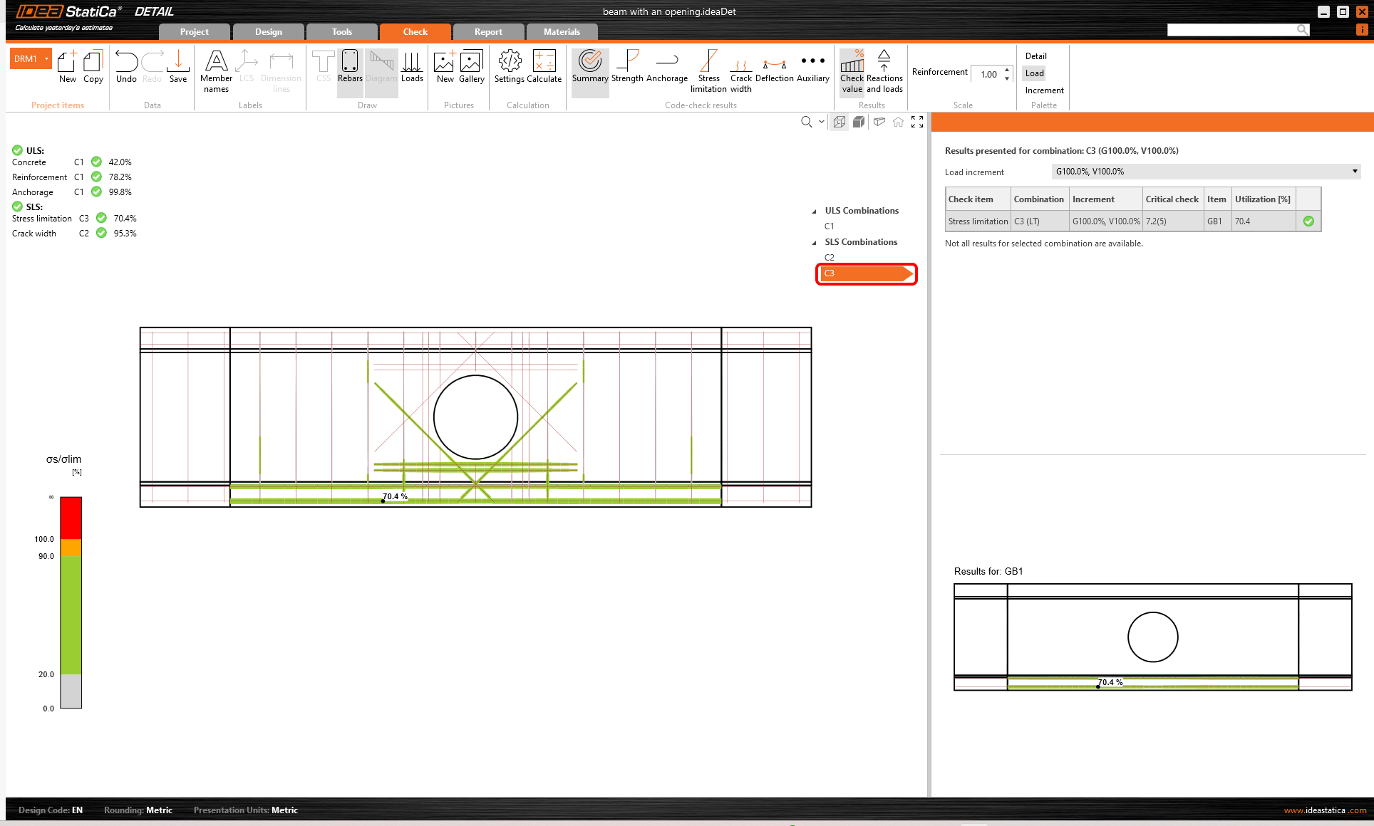
We open the SLS results by selecting a SLS Combination, e.g. C2 or C3.
To open the detailed results of ULS, click Strength in Code-check results. As noted above the table, C1 combination was used to check ULS.
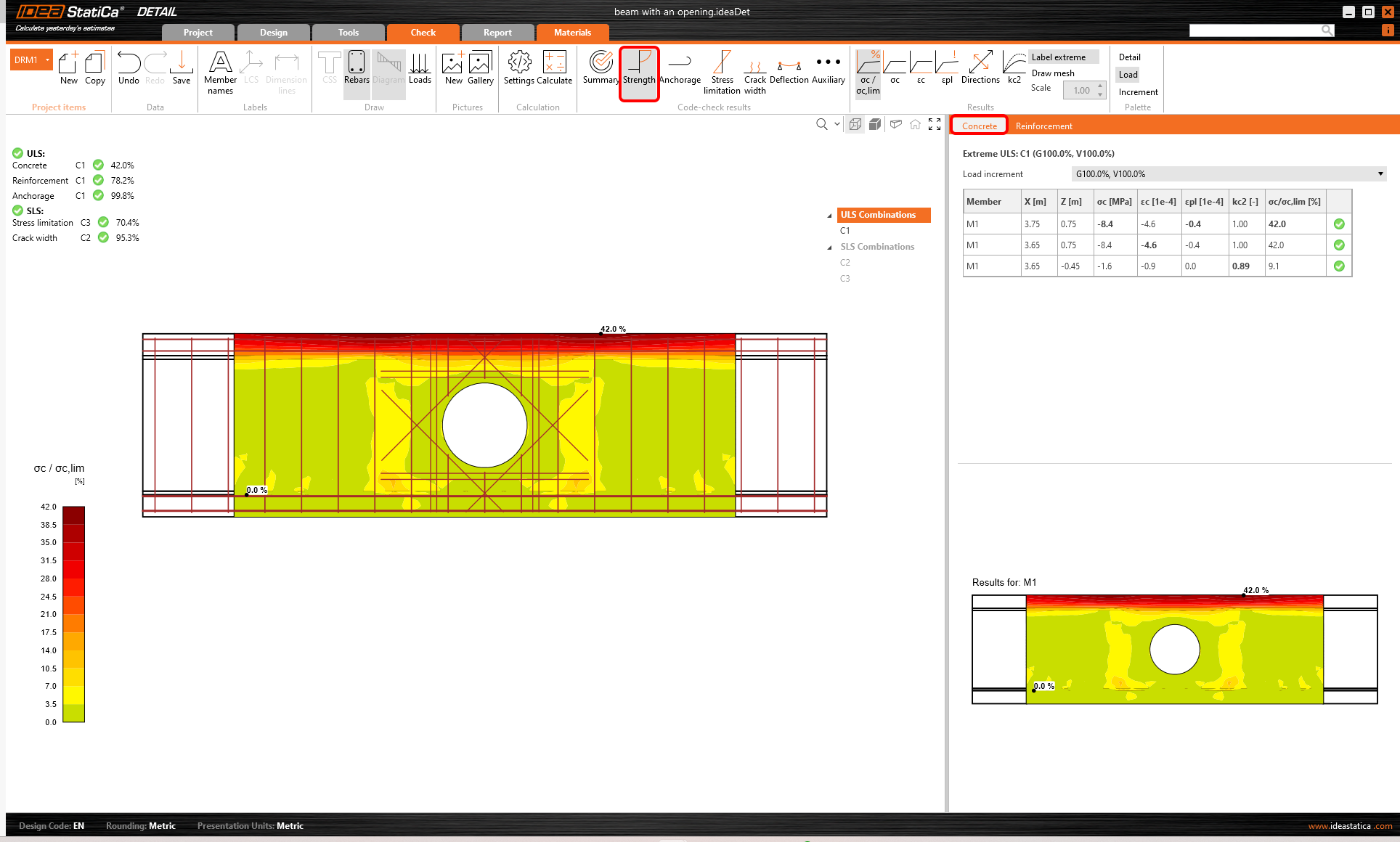
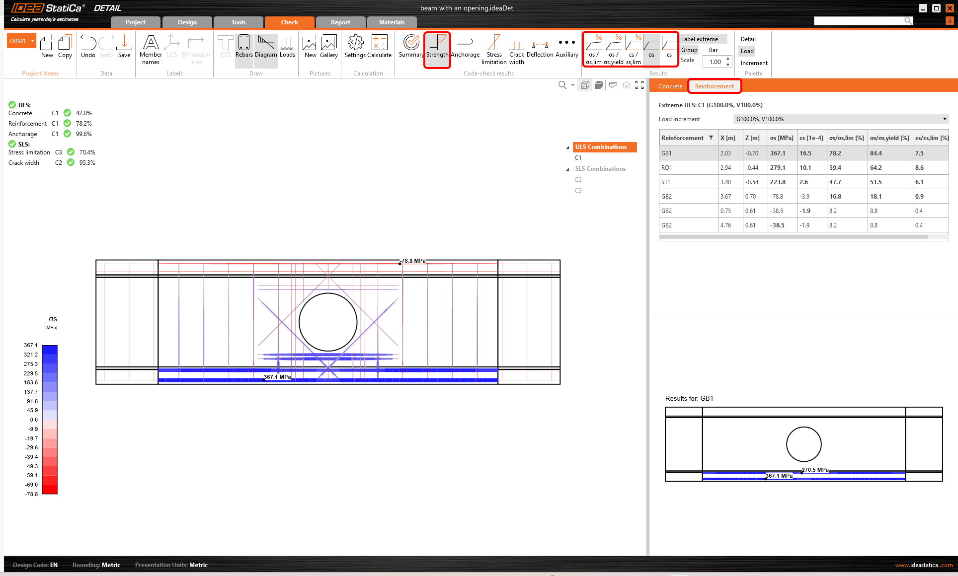
Again, you can display the results for Concrete and also for Reinforcement by selecting the corresponding tab above the table. You can select any bar of reinforcement to see its results of analysis and code check.
- More info about ULS results can be found in General description of ULS results in Detail application
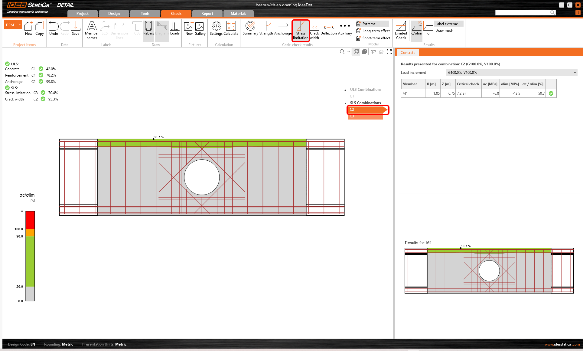
The detailed results of SLS can be found under Stress limitation, Crack width and Deflection. For the Stress limitation state, the stress in concrete is checked for both C2 and C3 combinations, while the check of reinforcement is applied only for the combination C3.
Calculated Crack widths can be displayed by clicking the corresponding icon. The calculated values are compared to the limit value w_{st,lim} which can be edited in the top ribbon.
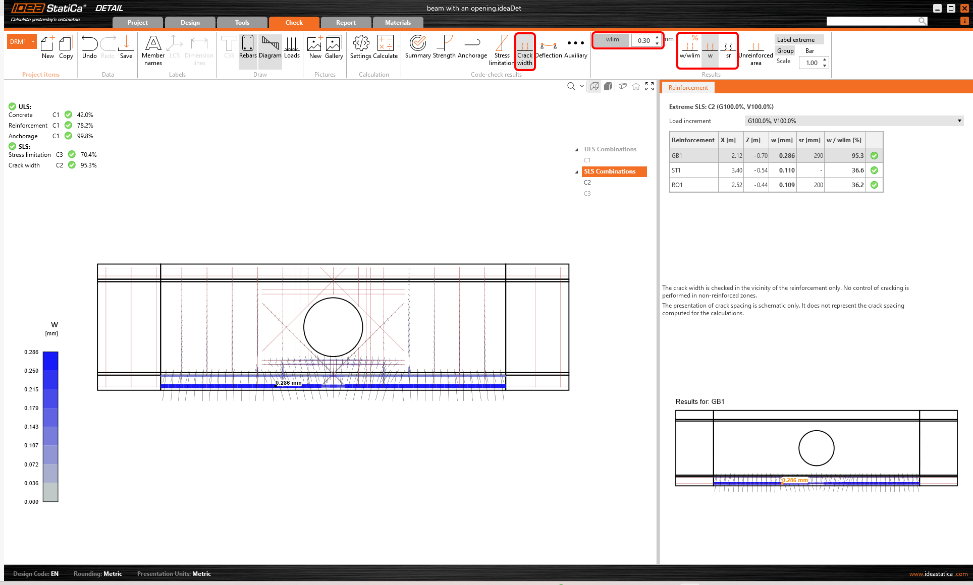
- More info about SLS results can be found in General description of SLS results in Detail application
6 Report
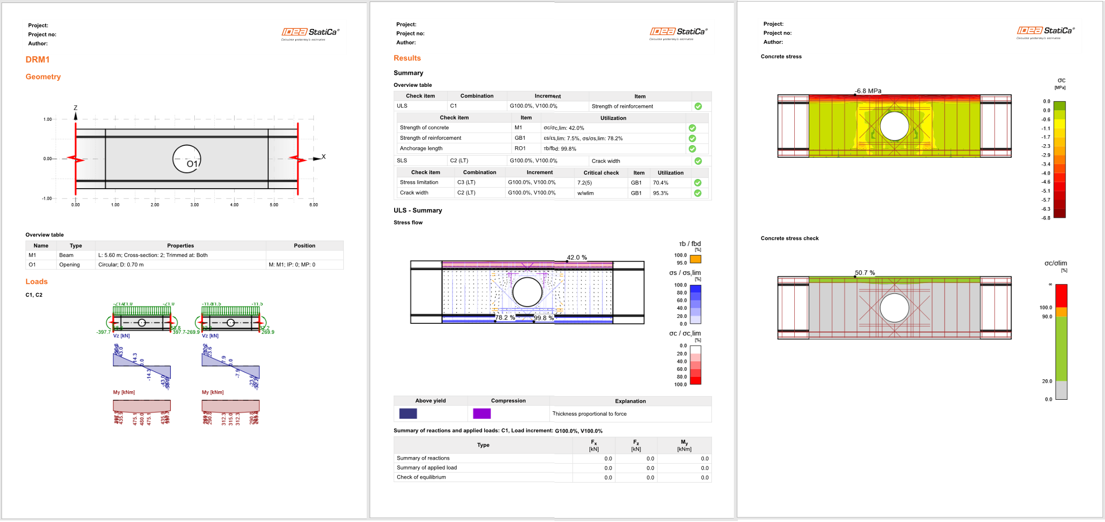
At last, go to the Report Tab. IDEA StatiCa offers a fully customizable report to print out or save in an editable format.
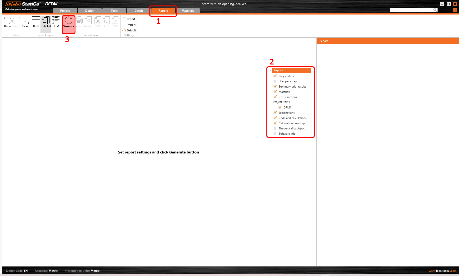
You have designed, optimized, and code-checked the part of the beam with an opening.