Structural design of a concrete wall (EN)
1 New project
Let’s launch the IDEA StatiCa Detail application (download the newest version). In the main window of IDEA StatiCa, open the Detail application to define a new project.

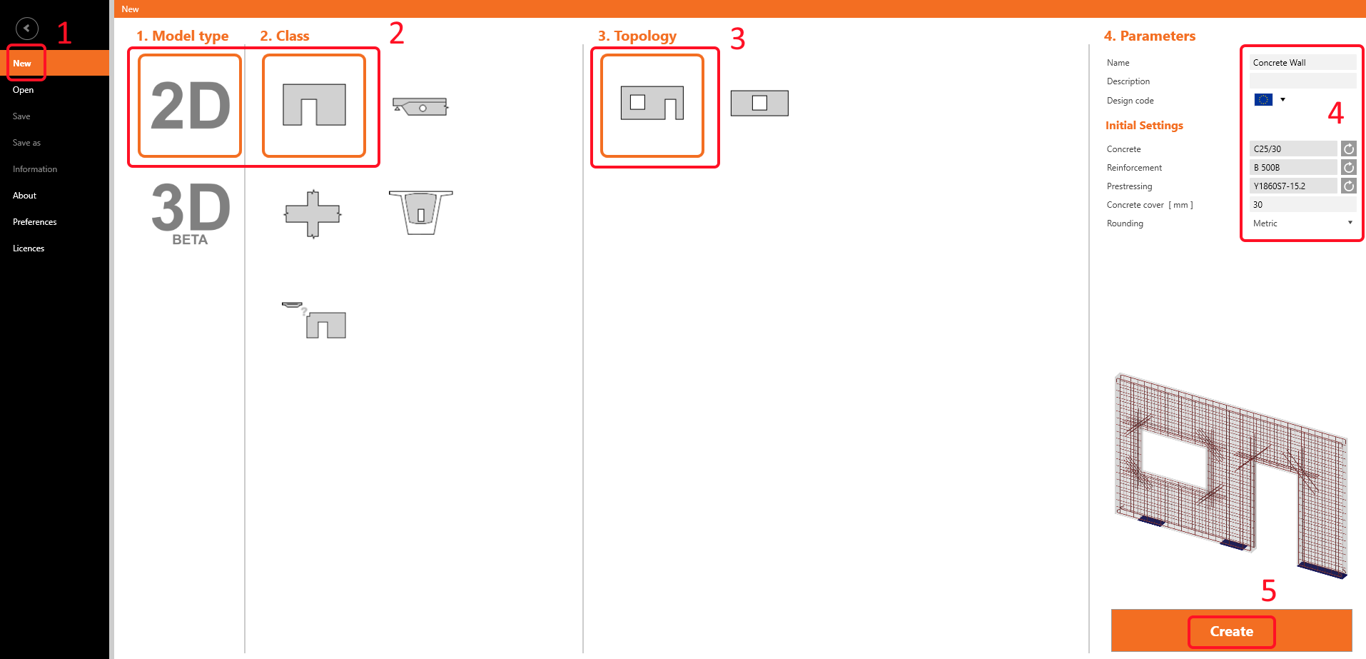
In the Discontinuity Region Wizard, select the 2D model type and tehn the Wall template. Select the topology of the discontinuity region – Wall with window and door openings. Finally, set the properties according to the picture (Concrete - C25/30, Cover - 30mm).
2 Geometry
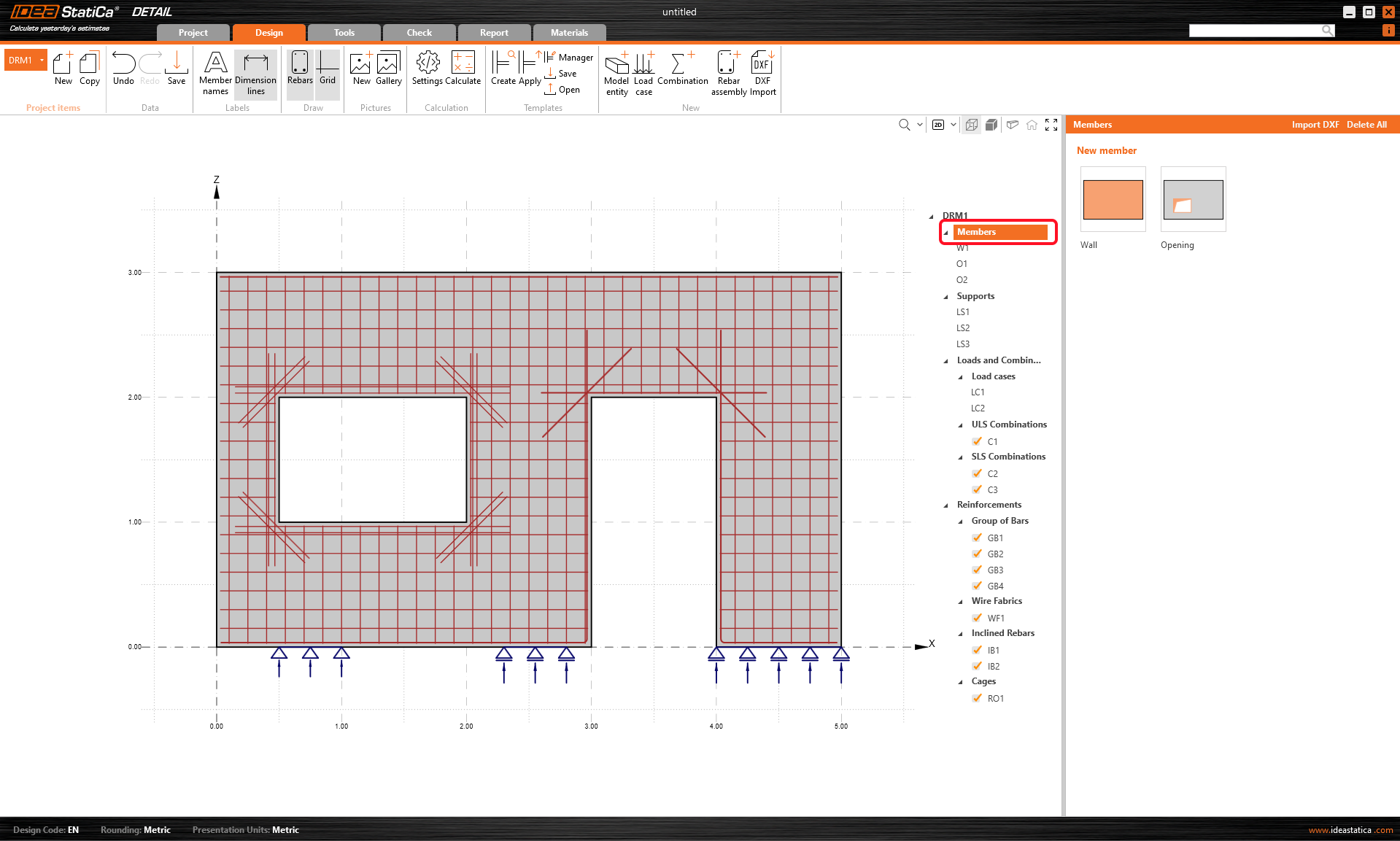
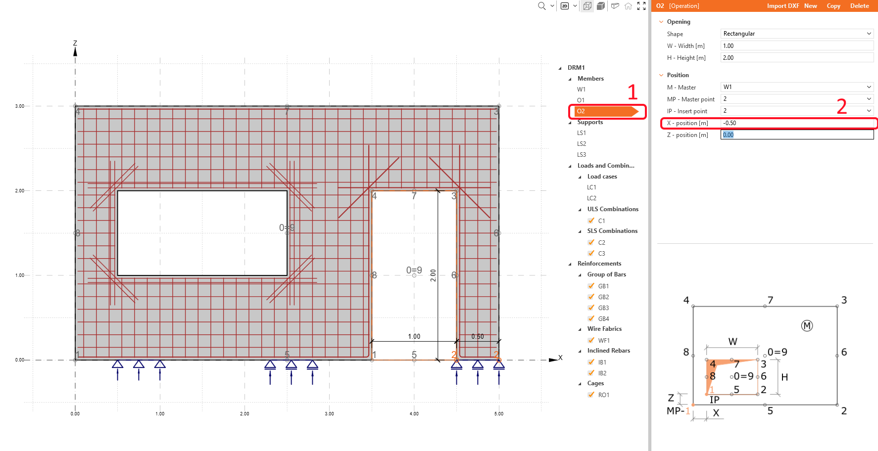
Start the definition of Geometry. Six items have already been created by the template: wall W1, two openings O1 and O2, and three line supports LS1-3.
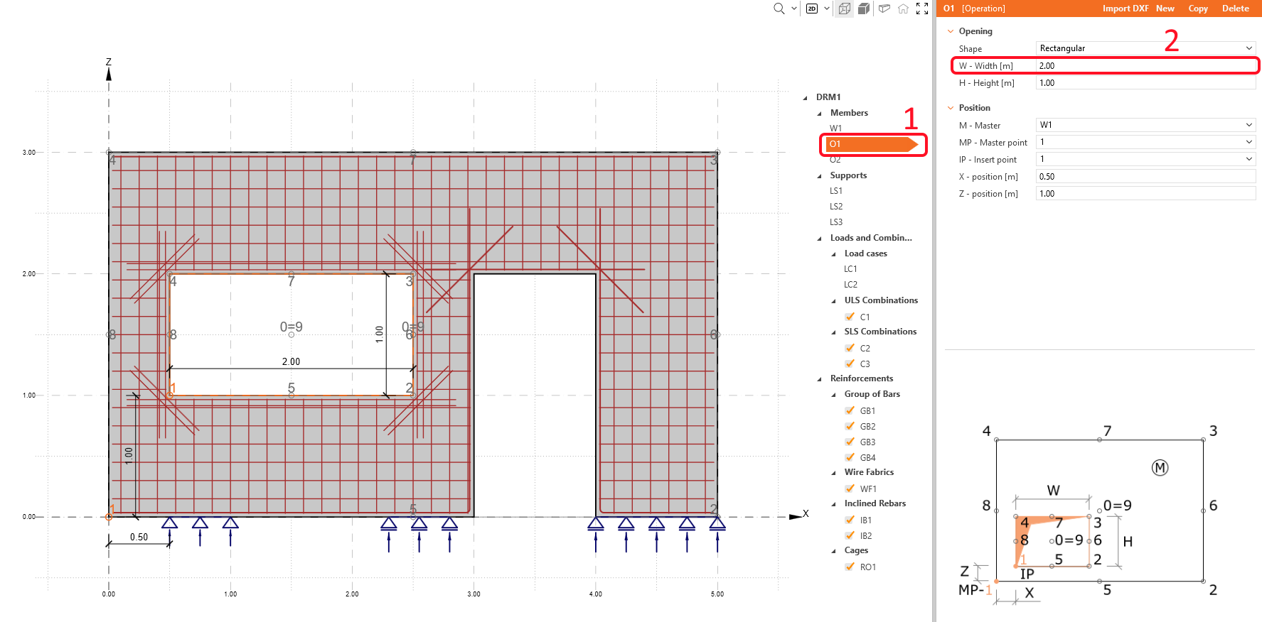
Select the opening O1 and increase the width of the window to 2m.
Shift the opening O2 rightwards by rewriting its X-position.
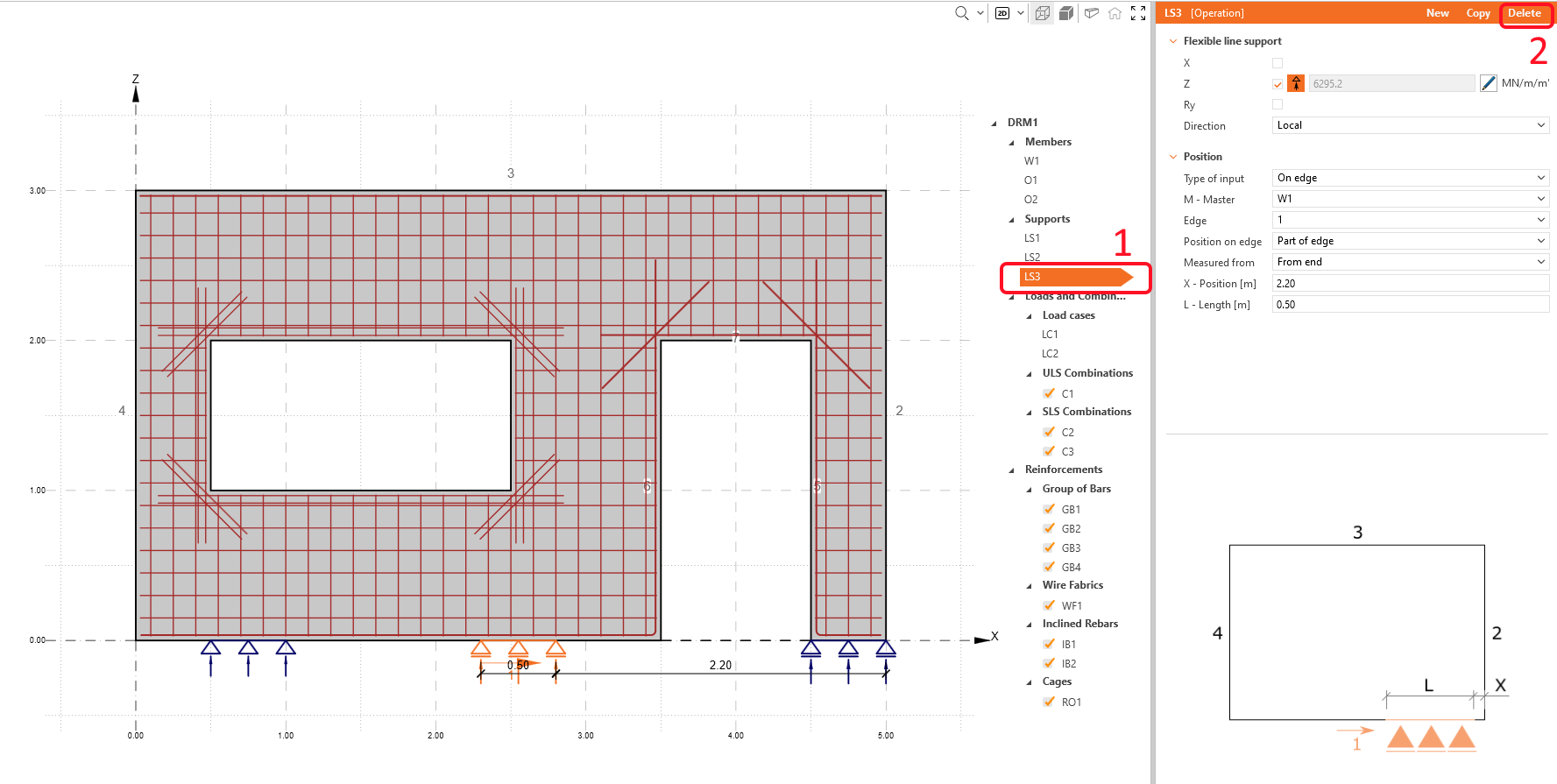
In this example, you will work with a wall supported by two linear supports. Select the third support LS3 by clicking on it in the tree of entities or by selecting the middle support in the 3D scene and then clicking on the delete icon.
The geometry of the wall looks like this, now:
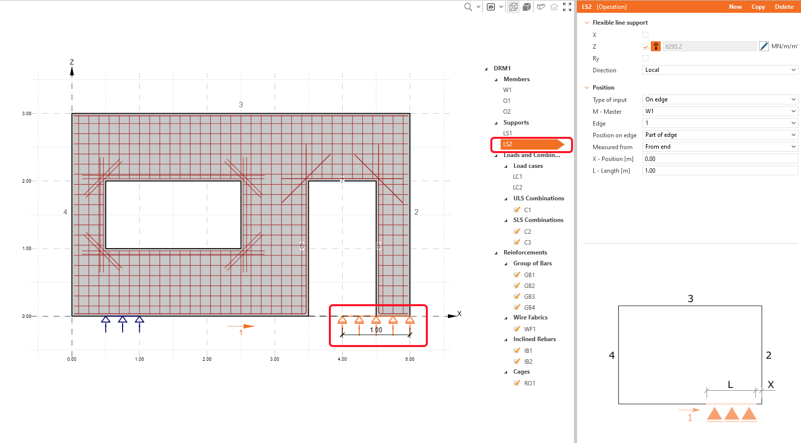
Don't be afraid about the overlapping support. It will be automatically adjusted to the geometry after selecting another item in the project.
- Read more about the geometry definition in Geometry types in Detail
3 Load effects
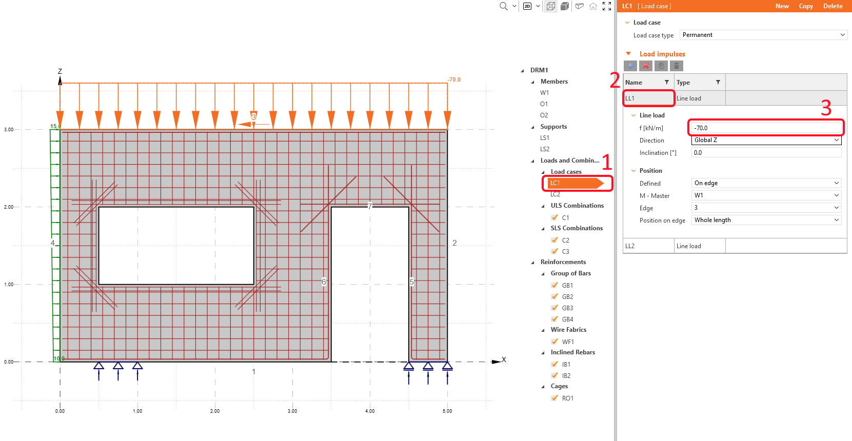
Now, move to the Loads and Combination section in the tree of entities. You can see, that two load cases and three combinations were already created by the template.
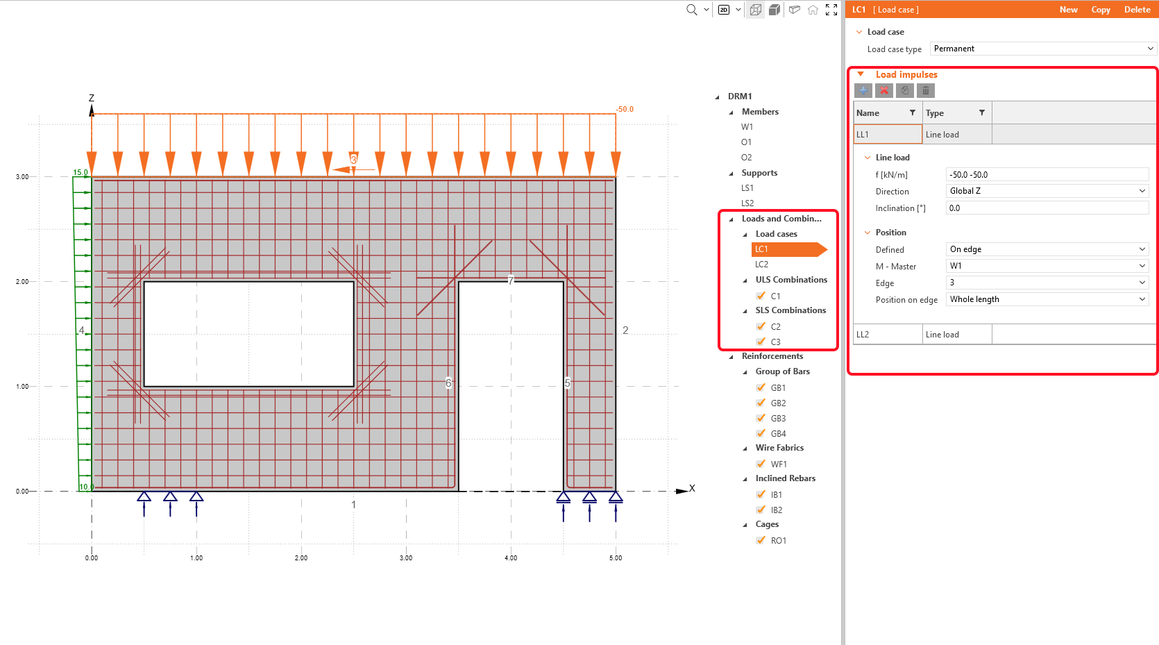
The load case LC1 (permanent) contains two line loads in Load impulses: uniform vertical load LL1 on the top edge 3 and linear horizontal load LL2 on the left edge 4.
Change the value of vertical load LL1, and keep the default value in linear horizontal load LL2.
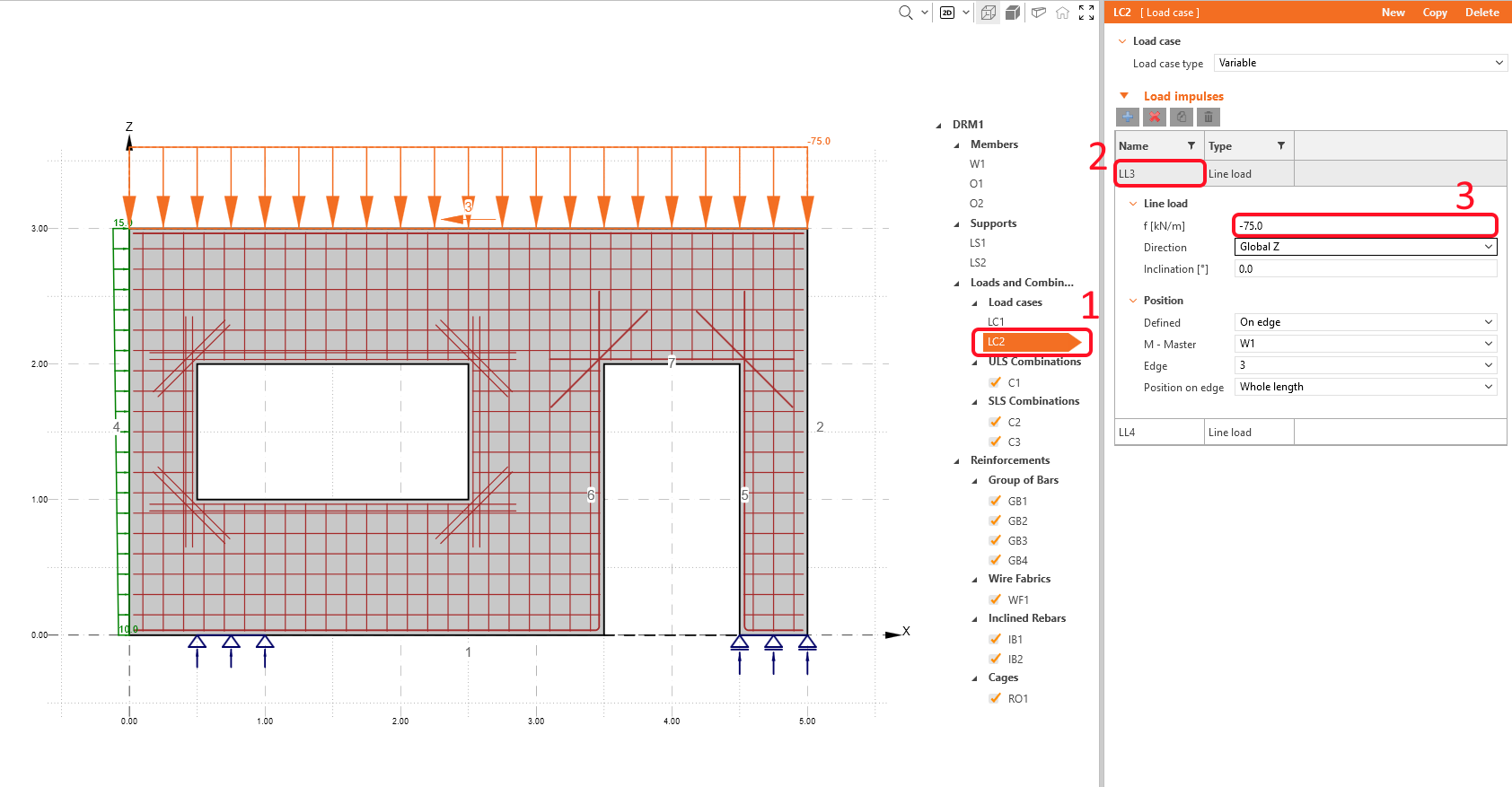
For the LC2, increase the value of the uniform line load LL3.
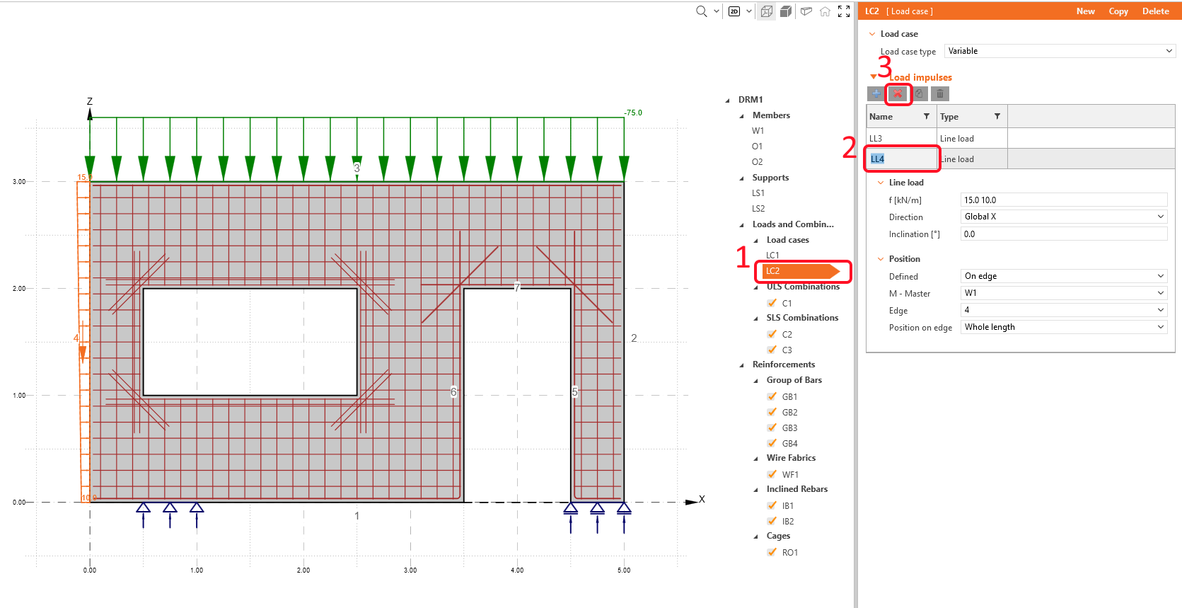
In Load impulses of LC2 (variable load case), delete the load case LC4.
Three nonlinear combinations were already defined: C1 stands for ULS checks. C2 is a quasi-permanent, and C3 is a characteristic load combination, both defined for SLS code checks (see the section Load cases & Combinations). The partial coefficients for the combination rules can be adjusted as well.
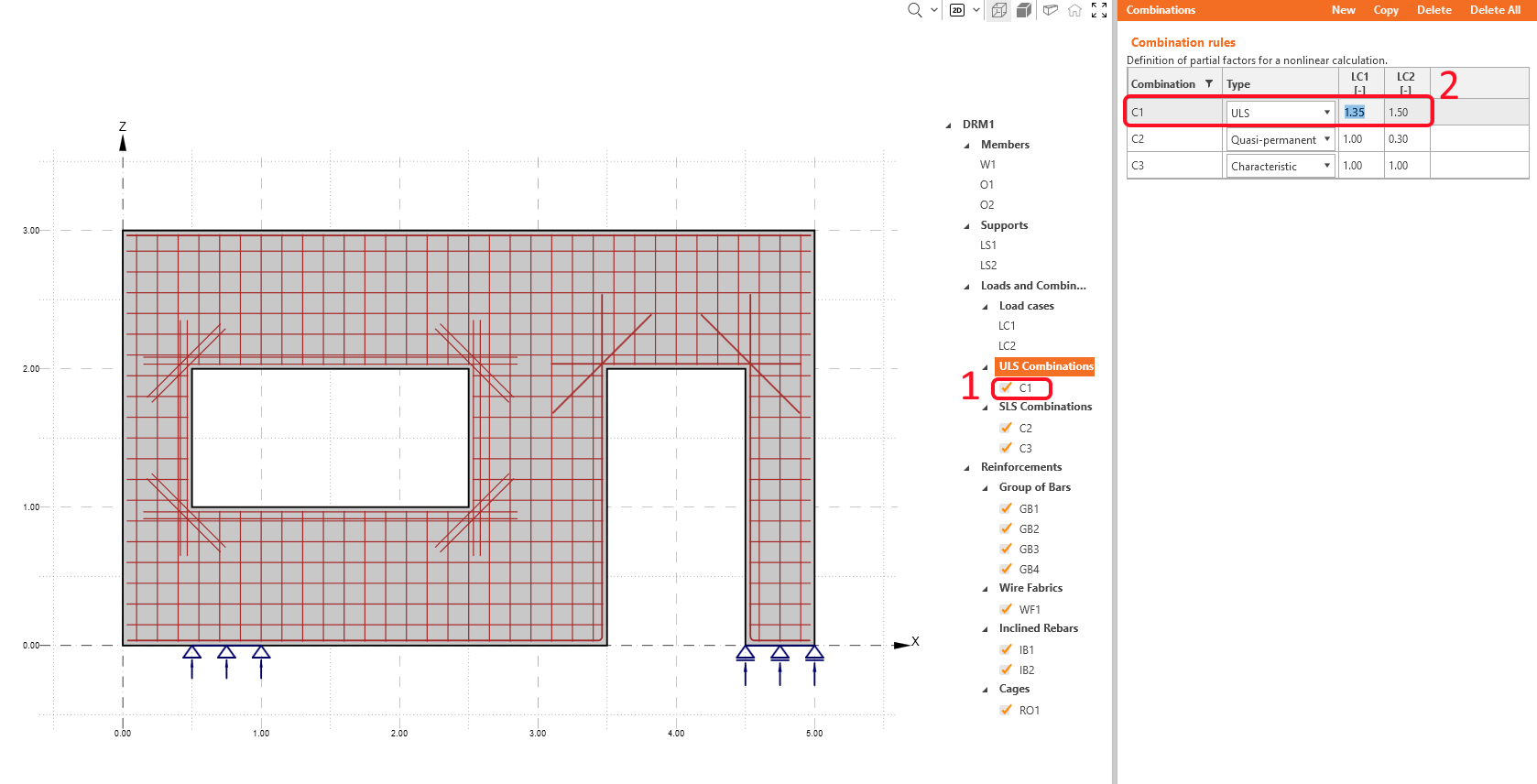
The calculations will be performed only for the checked items (combinations C1, C2, and C3).
- Learn more about internal forces in General description of Load impulses in Detail application
4 Reinforcement
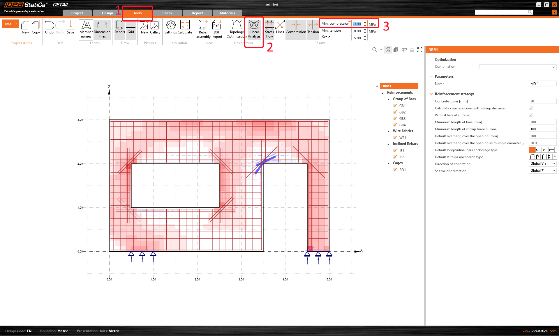
Before you start with the reinforcement definition, there are two design tools that can help you to understand the behaviour of the structure.
Linear analysis
Run the Linear analysis by navigating to Tools ribbon and then clicking on the Linear Analysis button in the top ribbon. To see the most compressed fields better, you can set the filter for Compression on -1.0 MPa in the top ribbon.
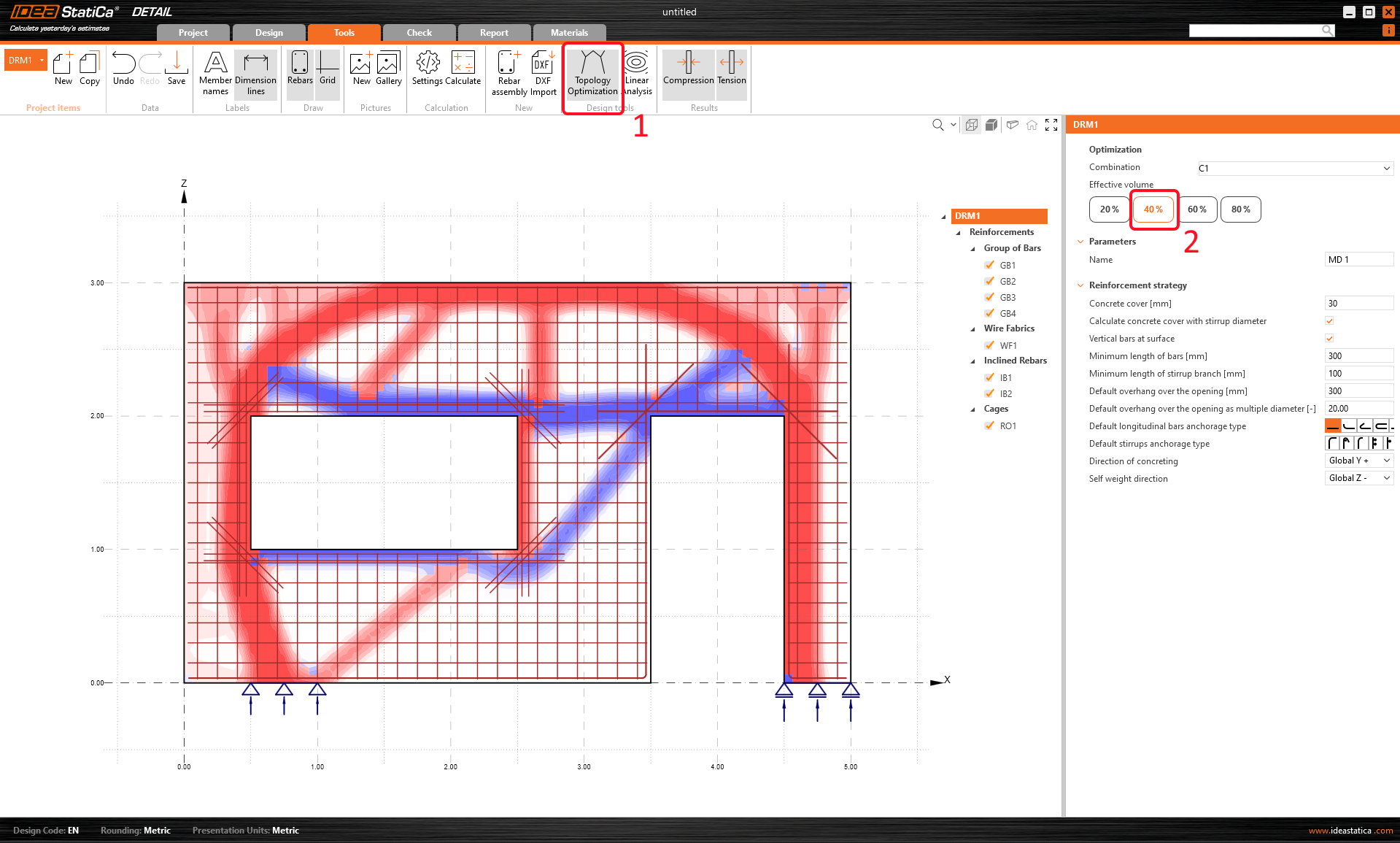
Topology optimization
Alternatively, you can use a more advanced Topology Optimization tool to see what the most effective reinforcement layout should look like.
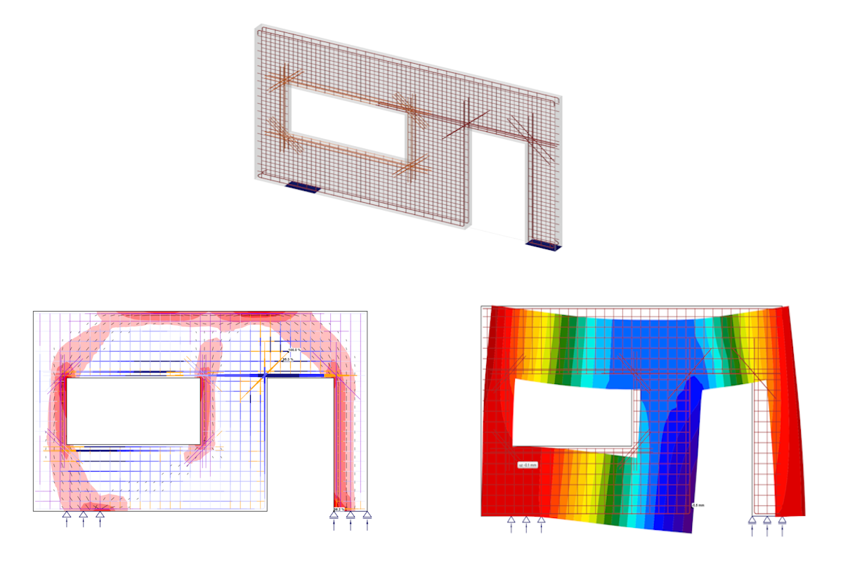
For the effective volume of 40%, the structure looks like this (again, red lines represent compression, and blue lines represent tension):
Let´s switch to Input/Edit of reinforcement layout. The results from design tools will remain in the background with lighter colors to see if your reinforcement complies with tensioned fields. If you do not want to display them, just click on the Design tool icon and it will be turned off.
You will exploit the 6 predefined items created by the template.
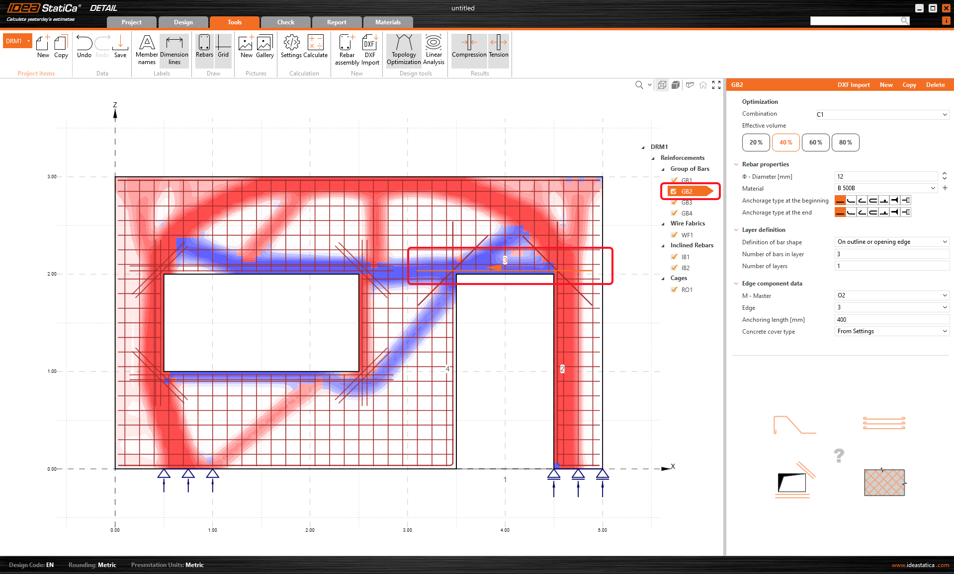
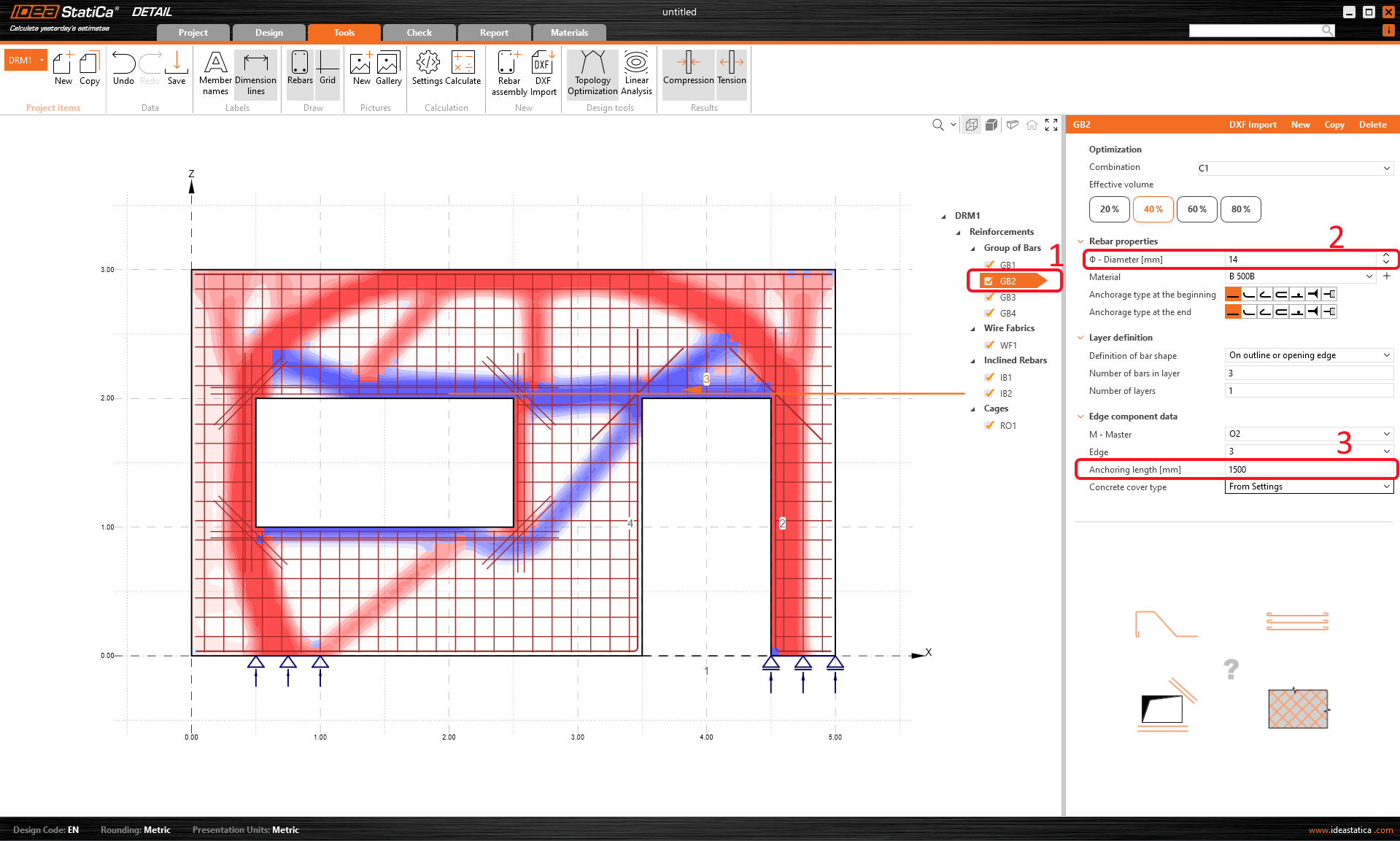
As you can see from the results of the Topology optimization, there is a tensile area above the door. Therefore, it is advisable to change the reinforcement in this area.
Select the group of bars GB2, and change the diameter and anchoring length. The small orange arrow in the scene defines the direction of the bars.
If you swith back to Design tab, you can display the Real 3D view on the top ribbon. However, the results of the precalculations have to be undisplayed first.
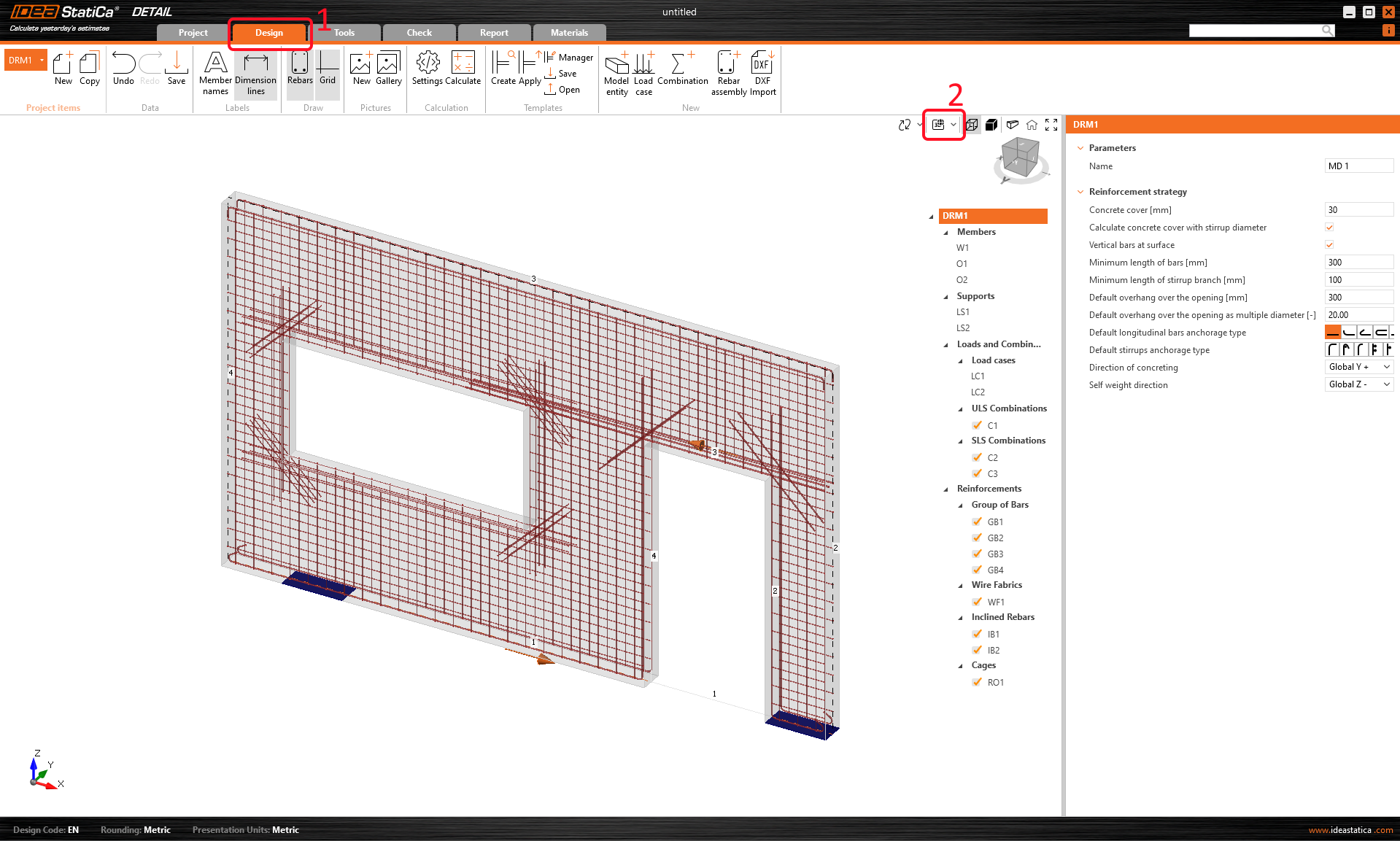
- Master your reinforcing skills by reading Reinforcement definition in the Detail application
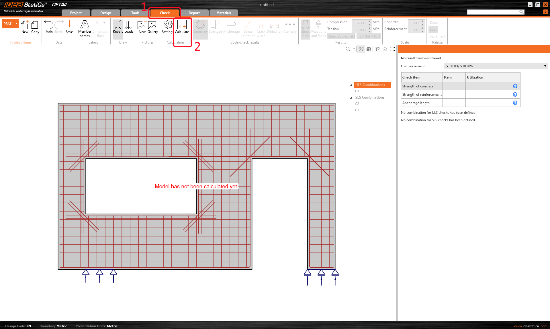
5 Calculation and Check
Proceed to calculate the project. Continue to Check in the navigator and press the Calculate button at the top ribbon. The analysis model is automatically generated, calculations are performed, and you can check the results.
In the property grid on the right, all detailed results can be found. Now the Summary check of the concrete in ULS combination (C1) is presented.
You can notice the portion of applied permanent and variable load (P100%, V100%.)
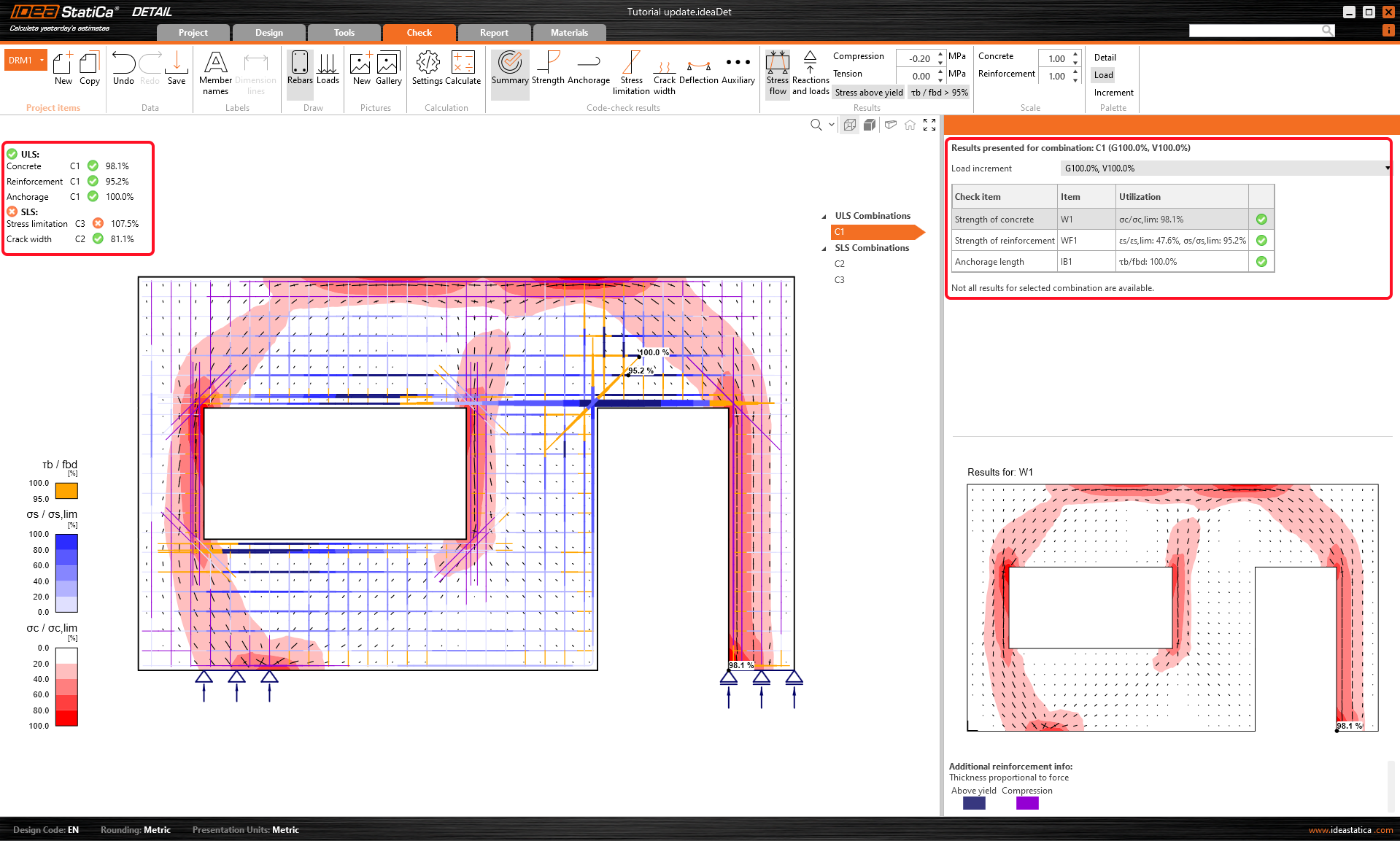
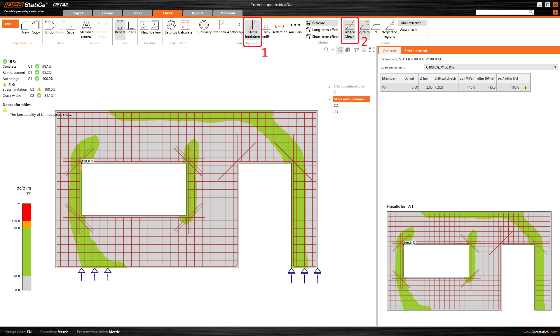
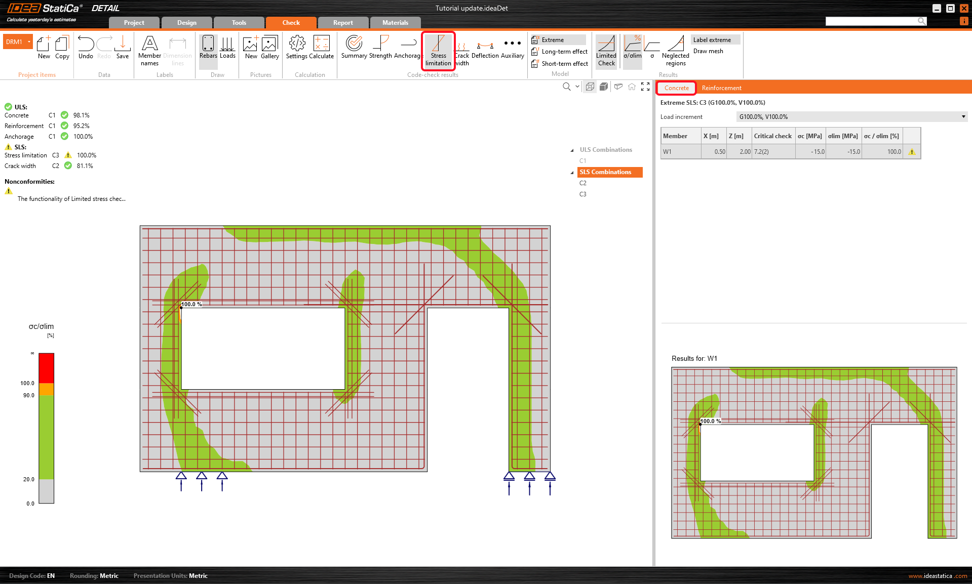
By changing the rows, you can display all the code checks. In the Summary, the main results for ULS/SLS are presented. As you can see from the picture SLS check isn't OK - stress limitation unsatisfied.
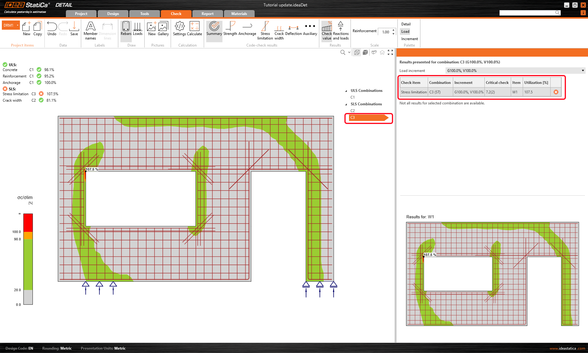
Go to the Stress tab. It's obvious that the unsatisfactory stress is in the window opening. There is a stress peak that can be neglected using the Limited Check button in the ribbon.
And with the button Neglected region, you can display the region. This figure will be added to the report to prove the size of the area which was neglected from the check.
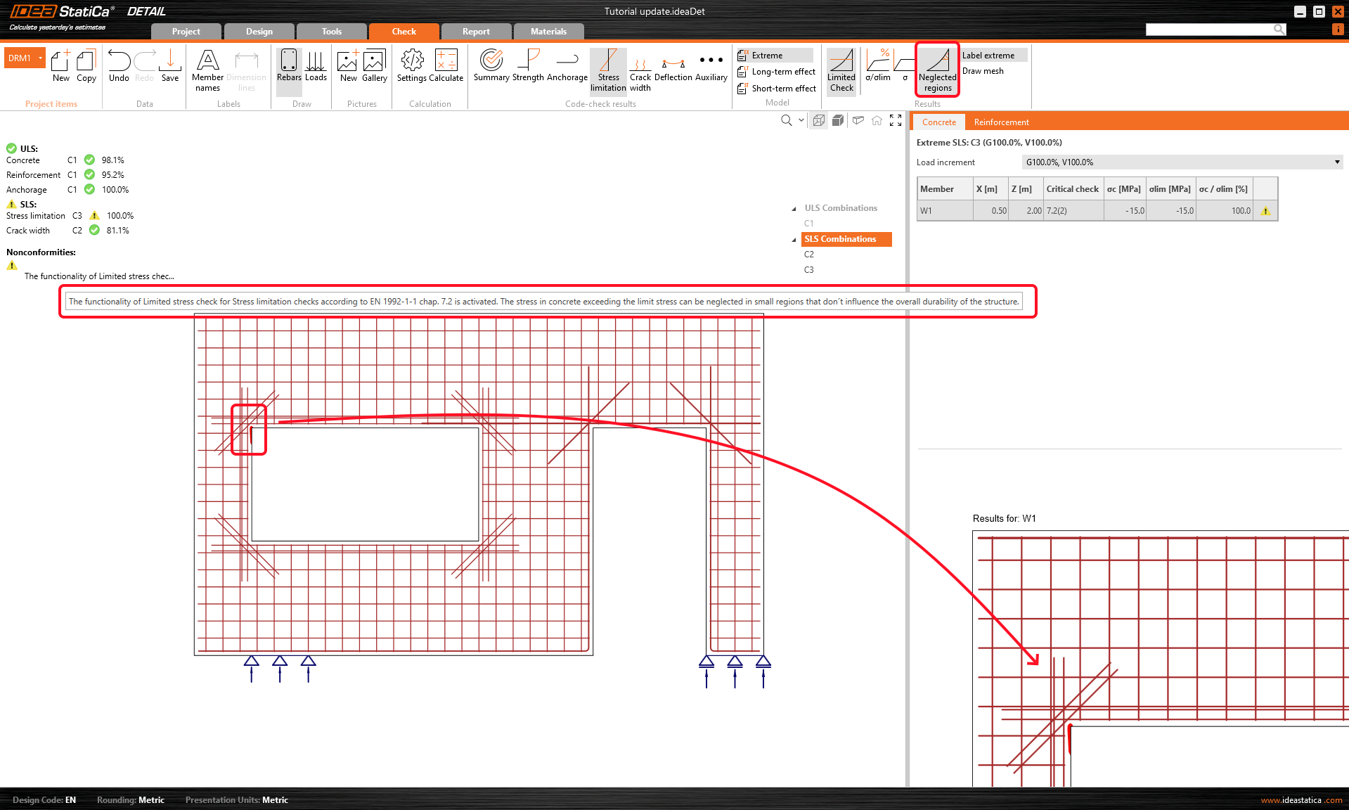
After using this function you will see a warning that it was neglected according to the code, the warning will be also included in the report.
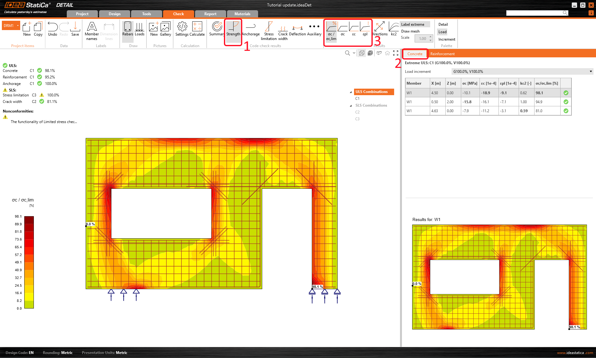
To go through the detailed checks of each component, start with click on the Strength tab. This will open concrete ULS checks such as utilization in stress, stresses in principal direction, strains, and also a map of reduction factor kc. As noted above in the table, the C1 combination was used to check ULS.
For better understanding read: Reduction of Concrete Strength by Kc2 factor in IDEA StatiCa Detail
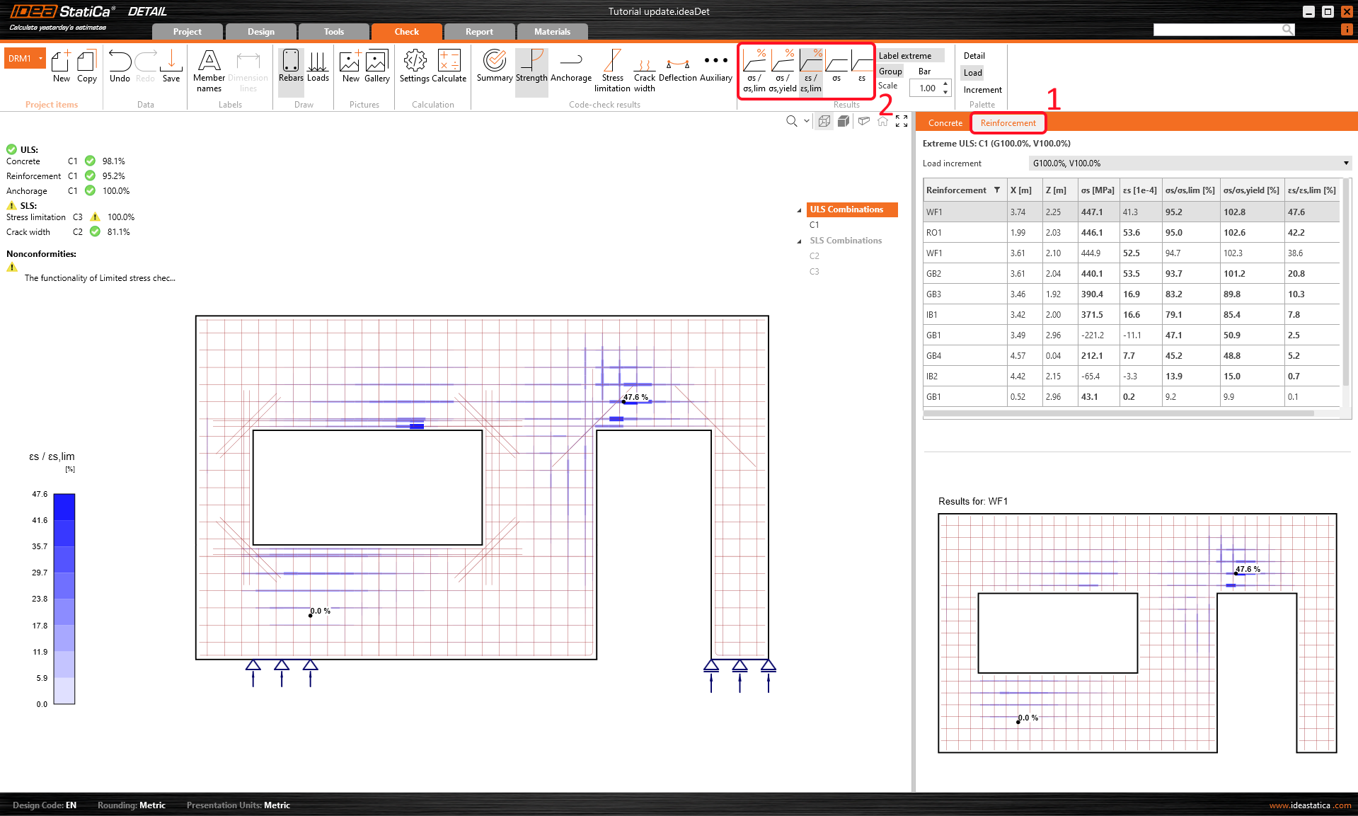
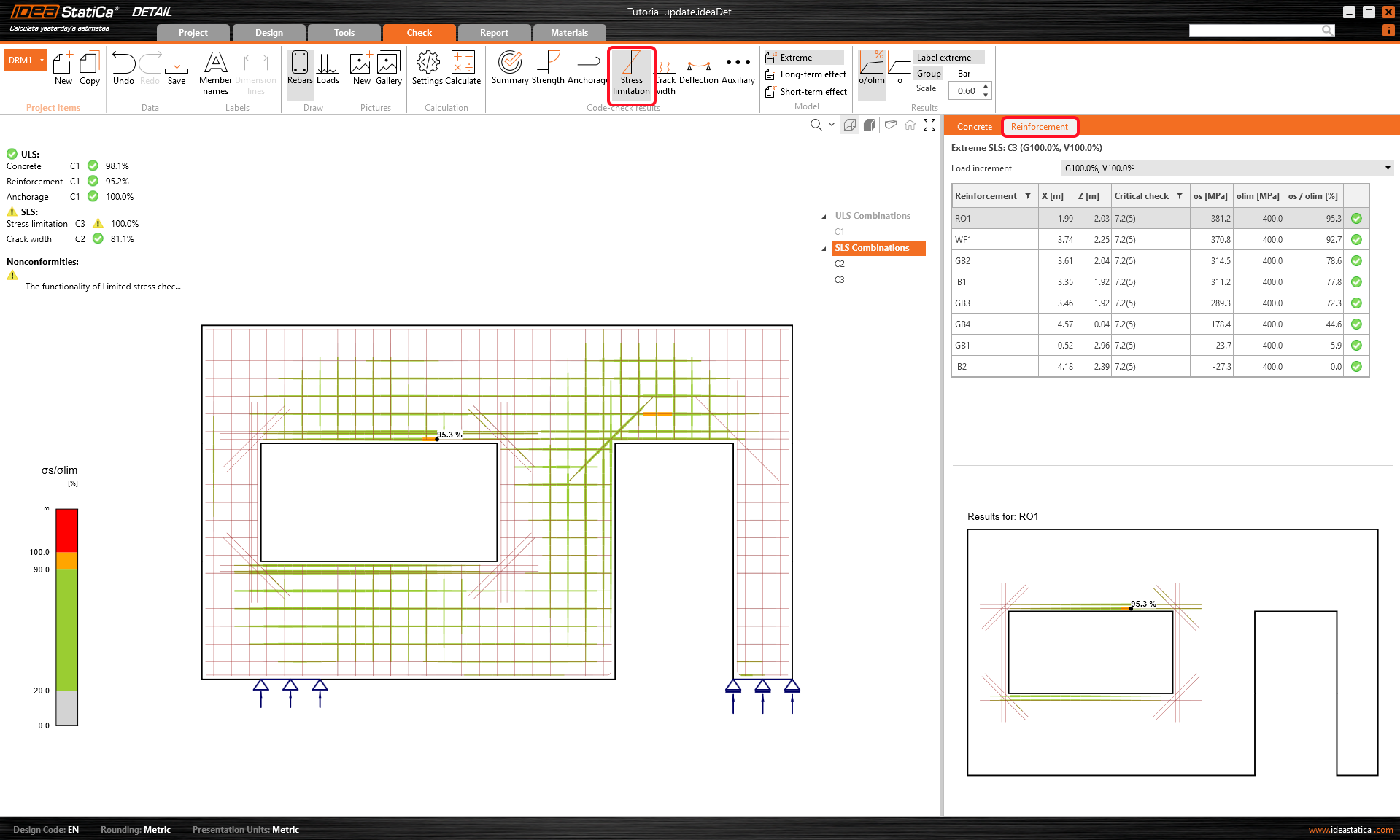
If you want to see such results for reinforcement, you need to click on the row with the Reinforcement title. This will change the ribbon options and also will unroll the table for results. You can display results for strains and stresses in each bar and their utilization.
In the Anchorage tab, you can show the results for the bond model and anchorage of bars. This includes anchorage forces, total forces diagrams along the rebars, bond, and slip. You can see the Total force that is carried through the selected group bars.
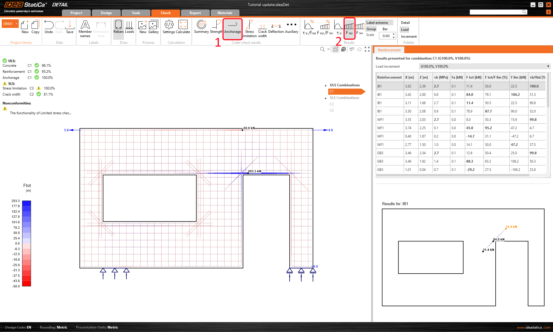
- More info about ULS results can be found in General description of ULS results in Detail application
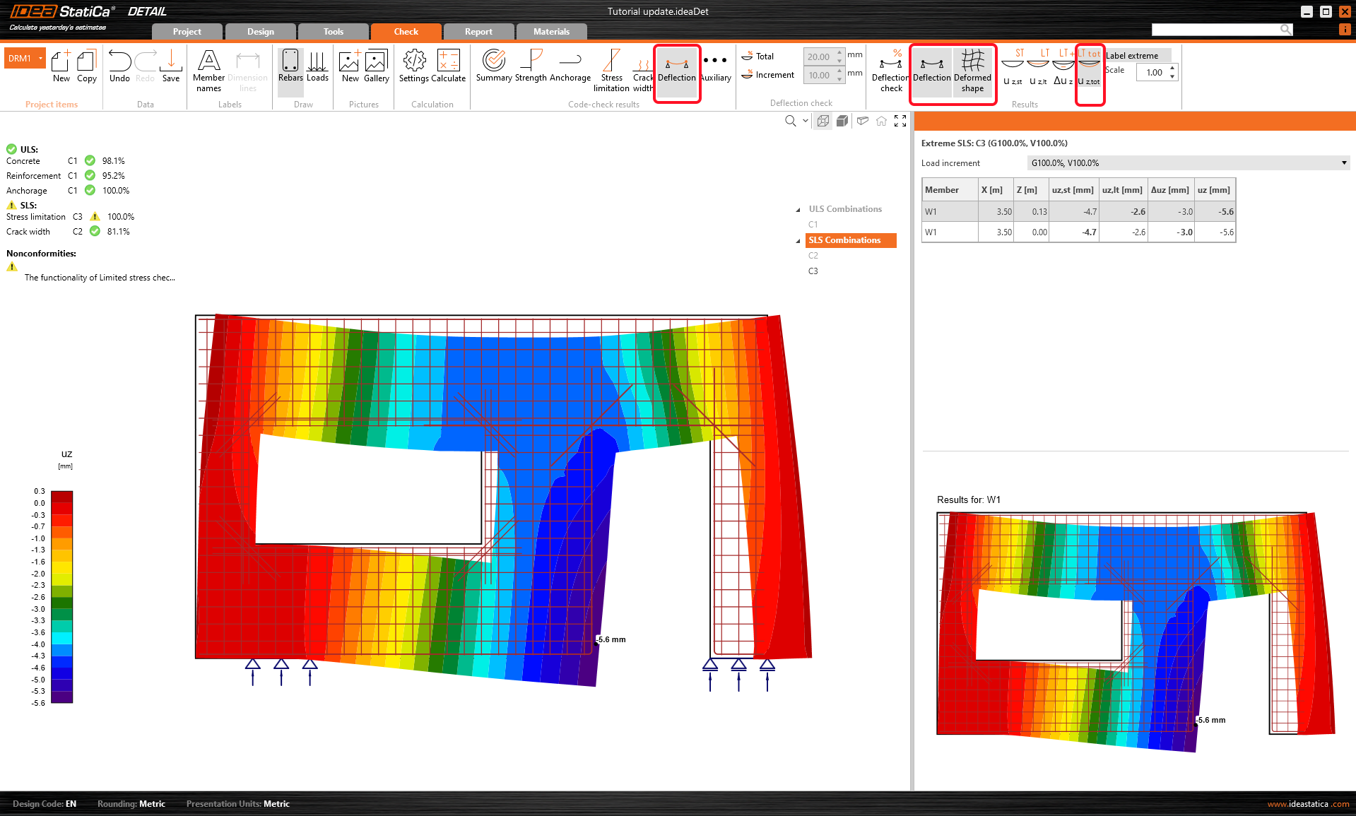
The results of SLS checks can be found in the Stress, Crack, and Deflection tab. For the Stress limitation state, the C2 combination was governing to check the concrete, while C3 to check the reinforcement.
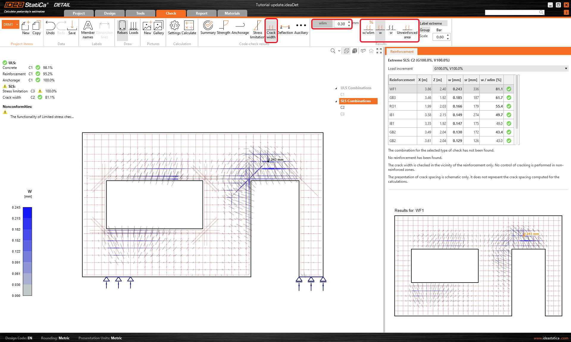
Calculated crack widths can be displayed in the Crack tab (combination C2). The calculated values are compared to the limit value wlim, in this case, 0.30 mm.
You can also look at the Deformed shape of the wall (top ribbon within the Deflection tab).
- More info about SLS results can be found in General description of SLS results in Detail application
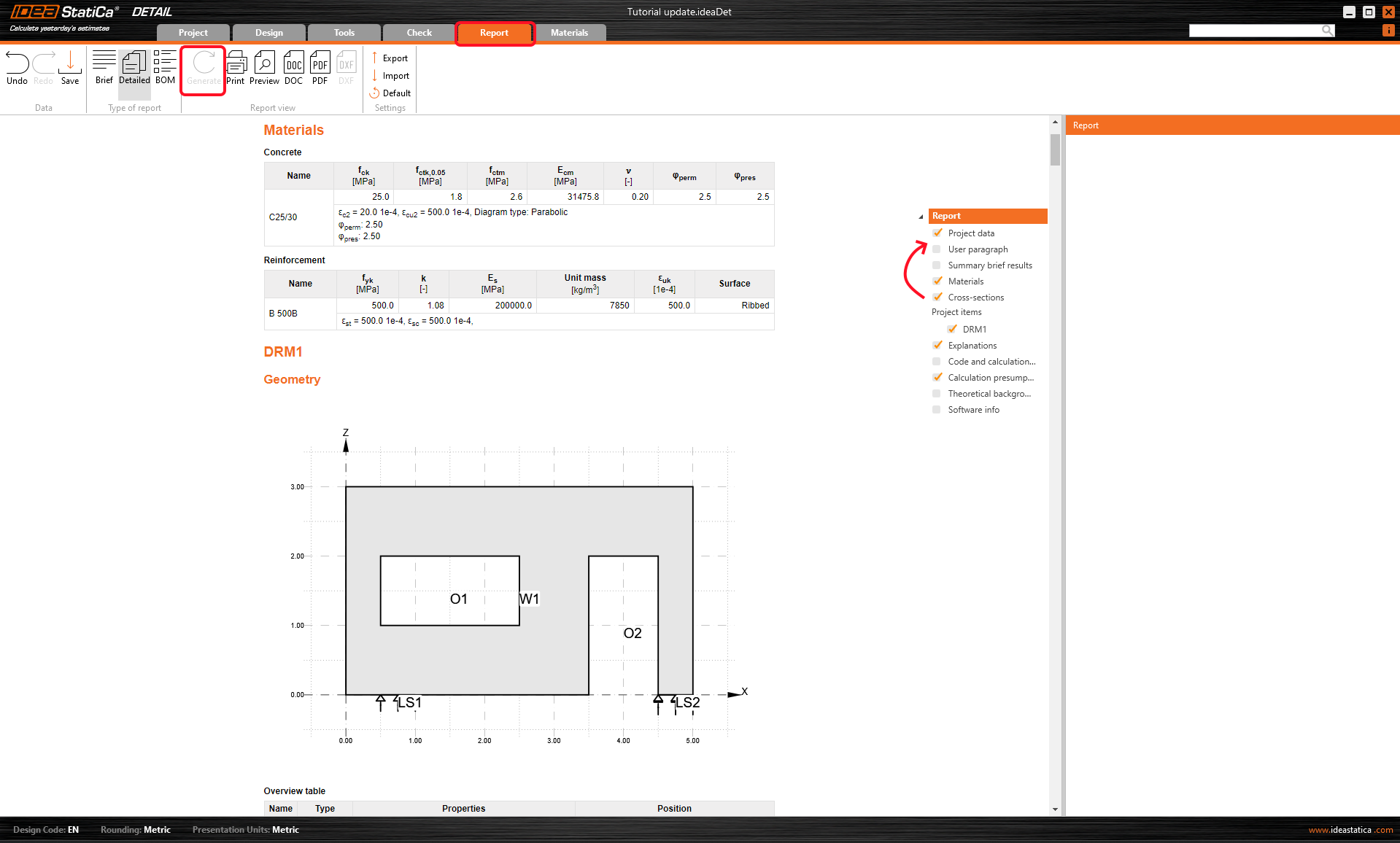
6 Report
At last, go to the Report Preview/Print. IDEA StatiCa offers a fully customizable report to print out or save in an editable format. By dragging the lines in the tree of entities, you can reorganize the structure of your report.

You have designed, optimized, and code-checked the wall with the openings.