Structural design of a pier cap from DXF (EN)
1 New project
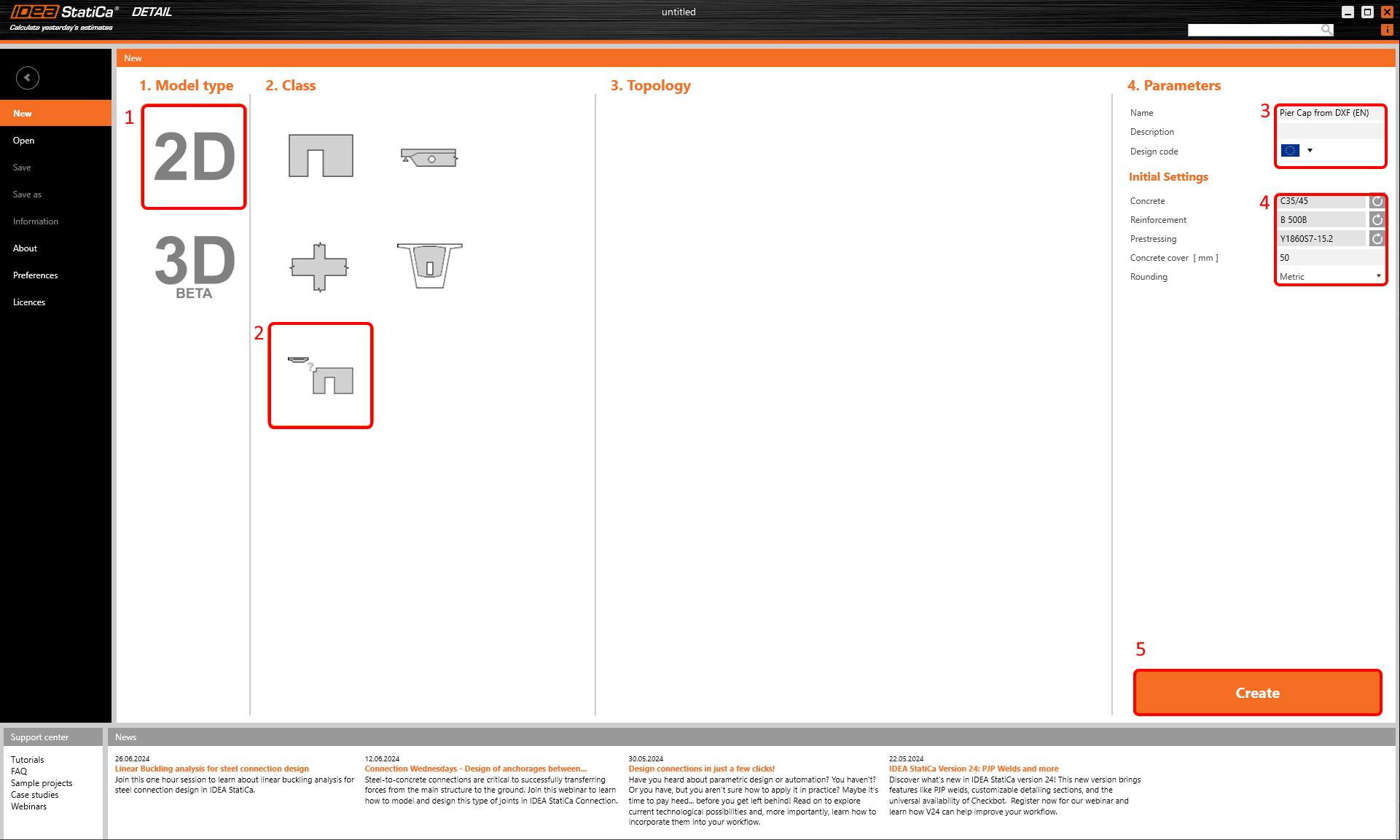
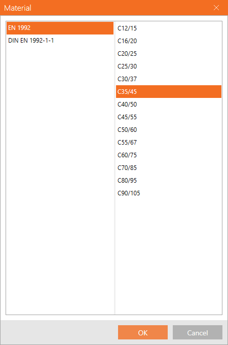
Let’s launch the IDEA StatiCa (download the newest version) and select the application Detail. Set up a new project by clicking 2D Detail with General input section, select proper concrete grade and cover. Finish setting by clicking Create.
This will load a blank project where we start from scratch.
2 Geometry
Start with the addition of a wall element by the DXF Import button.
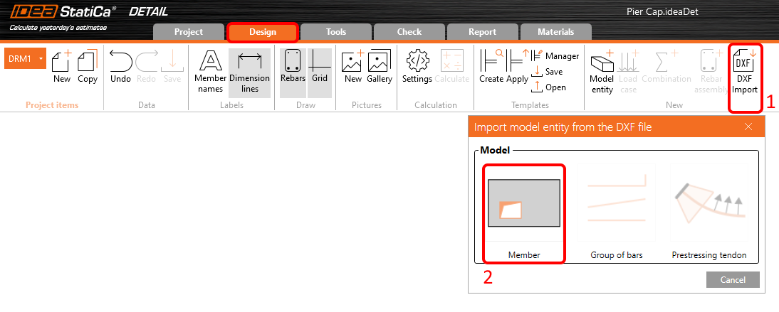
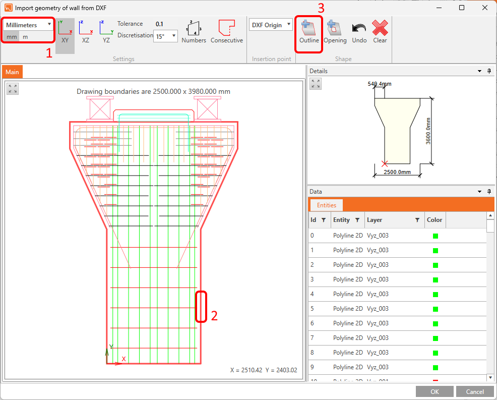
A dialog to locate and open the desired DXF file will pop-up. After the selection of pier_cap.dxf (available in source files), you will land in a dialog for selection. Select the part of the outline of the pier cap (if you used lines in DXF continue with Consecutive button) and click on Outline. Finish the selection by OK button.
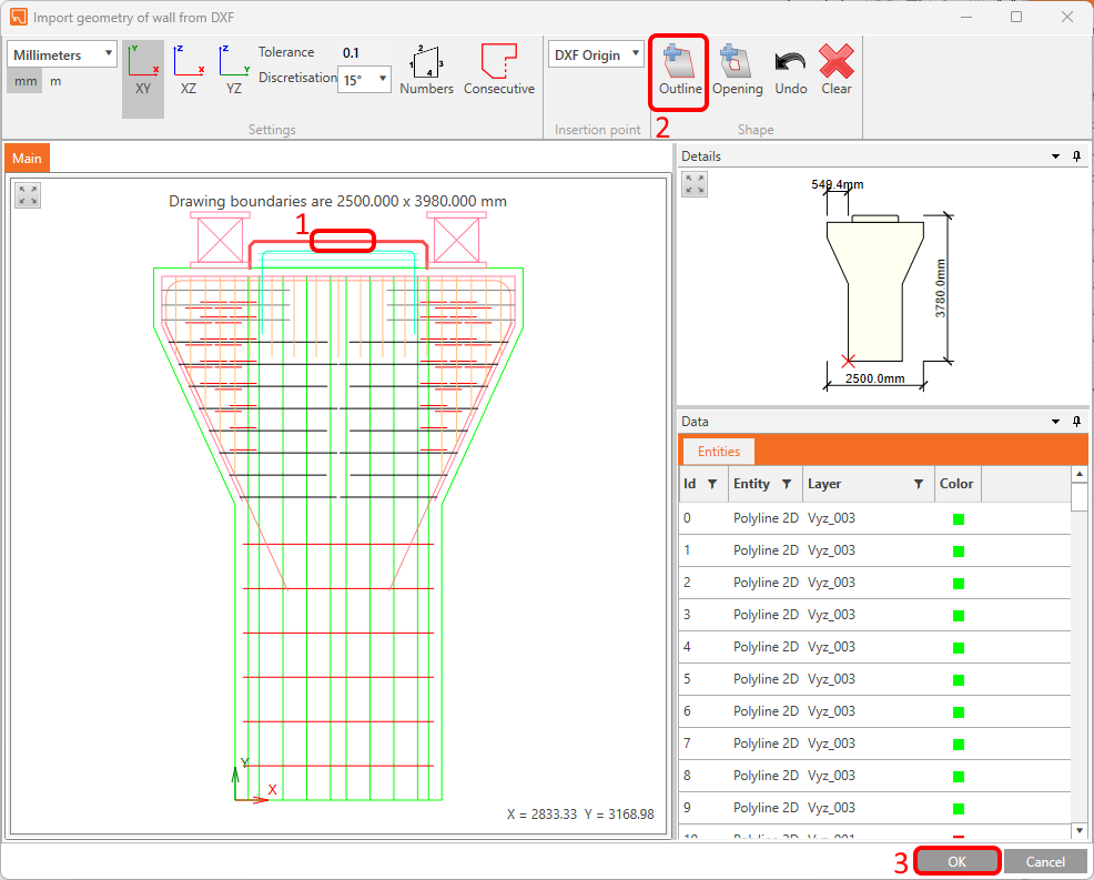
Then import the upper part of the pier cap from the same DXF file.
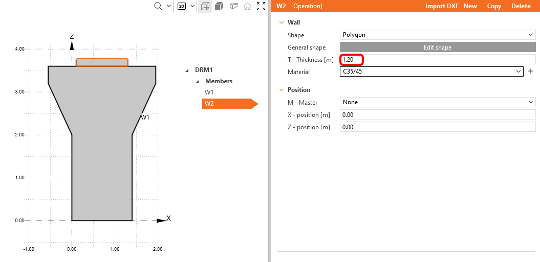
The shapes of the wall elements have been generated by DXF, but the 2D DXF reference lacks the information about thickness, thus you need to adjust it manually now. Set the Thickness for both W1 and W2 members to 1,20 m.
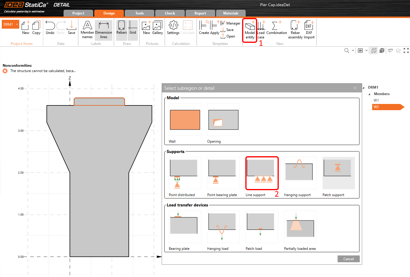
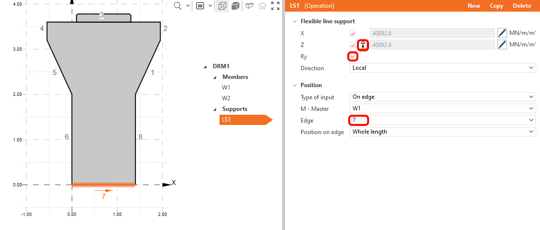
Right now, our structure is statically overdetermined, you need to add boundary conditions. To create line support, click on the Model Entity button and select the third type in Supports section.
Constraint the support in X, Z and Ry directions and change the edge number to 7. Also, switch off the Compression only functionality. The edge numbers can be seen in the Main window.
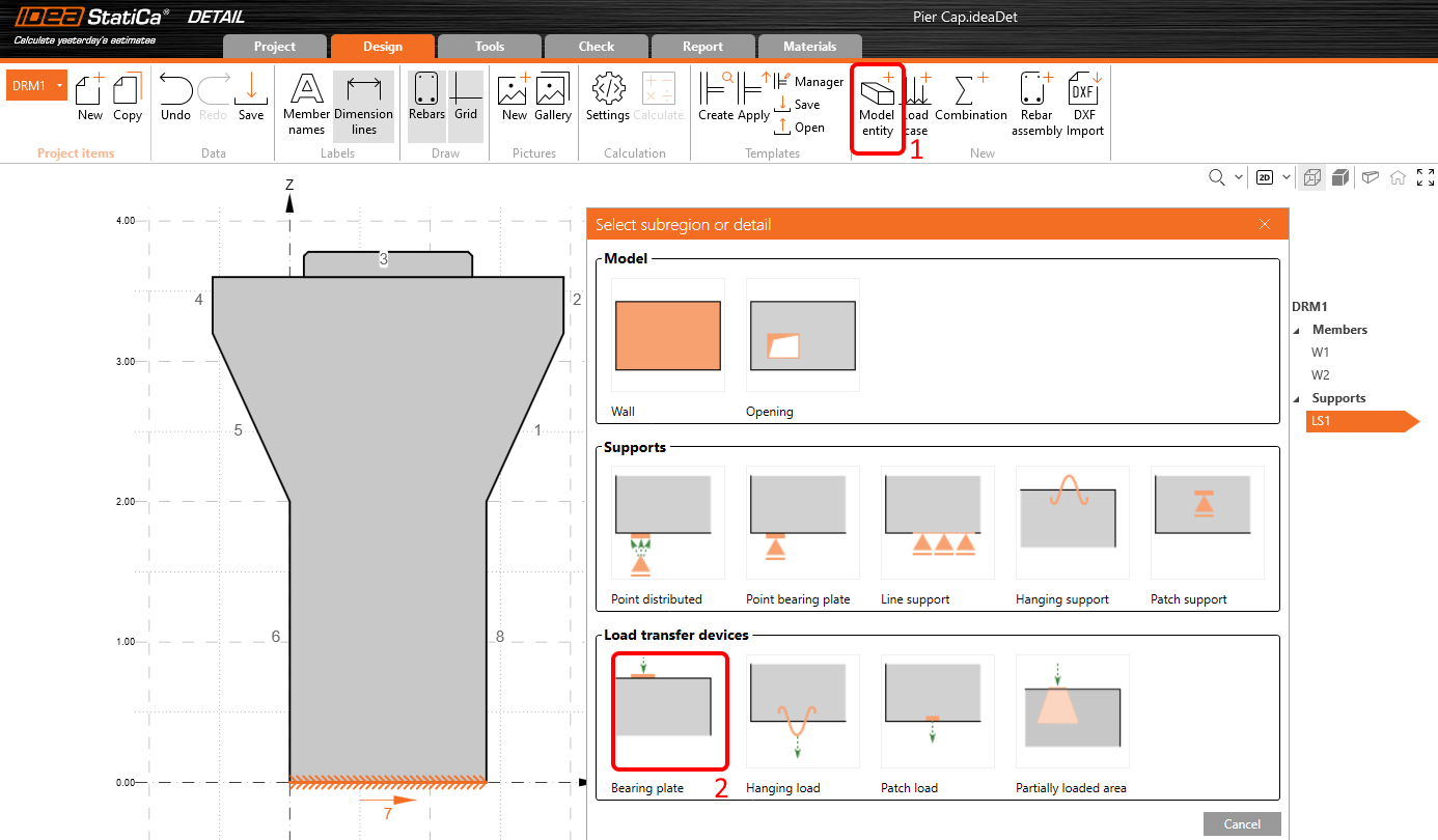
As a Point force-placed directly on the edge of a pier cap would crash the concrete locally in compression, we will use bearing plates to distribute the load more evenly. To add one, press Model Entity button once again, and in the Load transfer devices section, pick the first - Bearing plate.
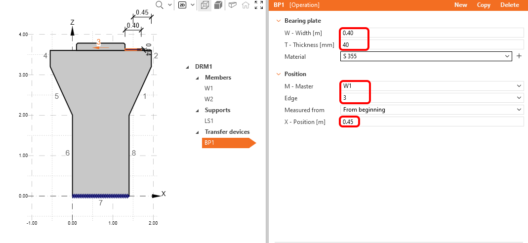
Change the Width to 0,40 m and the Thickness to 0,04 m, then the Edge number to 3 and shift its X-Position to 0,45 m.
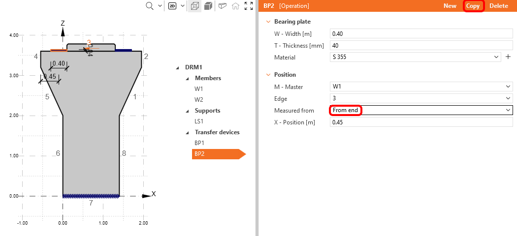
Then copy the Bearing plate and change its position to be measured From end.
3 Loads
Load Case will be created by clicking Load Case button and its for Permanent effects by default. You need two load cases to distinguish between permanent and variable loads and three combinations to cover one ULS and two SLS combinations (Characteristic and Quasi-permanent) for all checks.
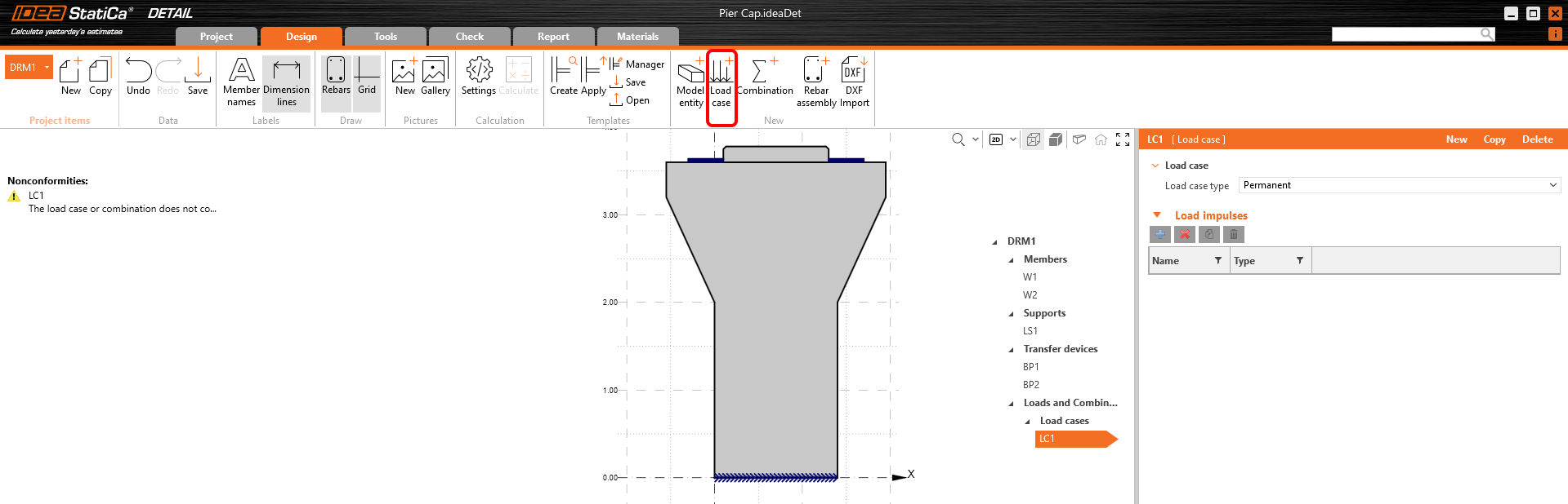
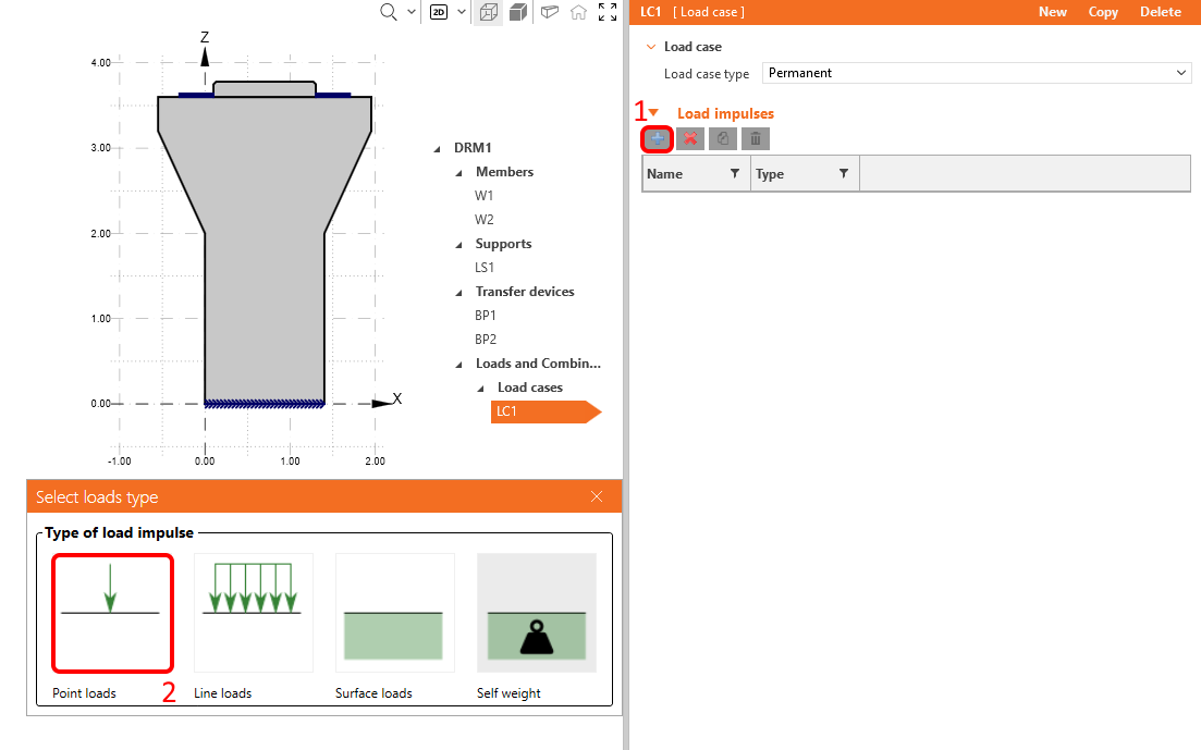
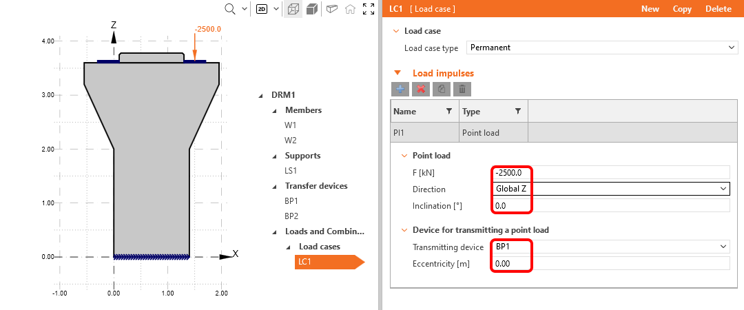
Let's modify the automatically added load case LC1 for permanent effects. In the Load impulses tab, click on the Plus button and apply a Point load. It will be automatically placed on one of the bearing plates.
As the last step, change its value to -2500 kN.
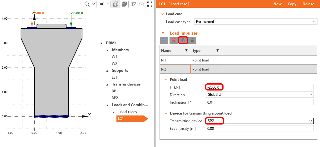
Copy that Point load to the other bearing plate BP2.
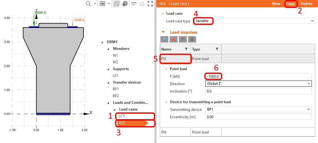
Copy Load Case 1 and change the LC type to the variable. Click on Point Load and change force to -1000 kN.
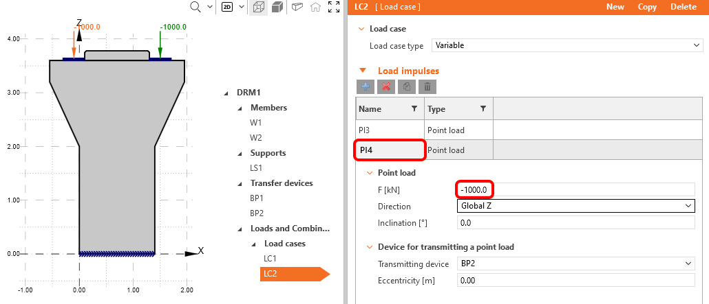
Repeat the steps for the last point load.
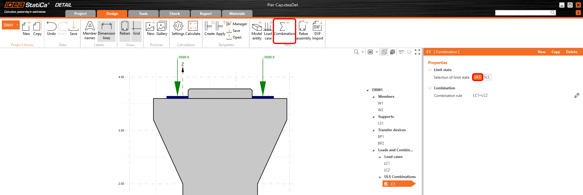
Create the first nonlinear combination by Combination button, and set it as ULS limit state.
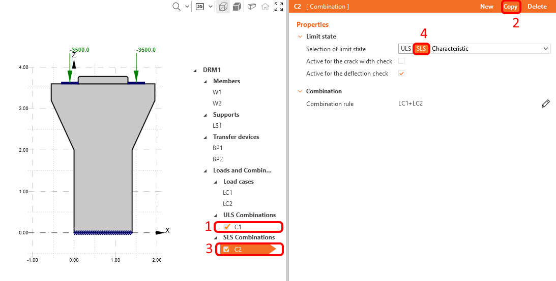
Copy C1 and choose SLS Characteristic. In addition, the option is available to check the combination on deflection and crack width both for a given combination and individually. For Characteristic combination choose Active for deflection check according to the picture below.
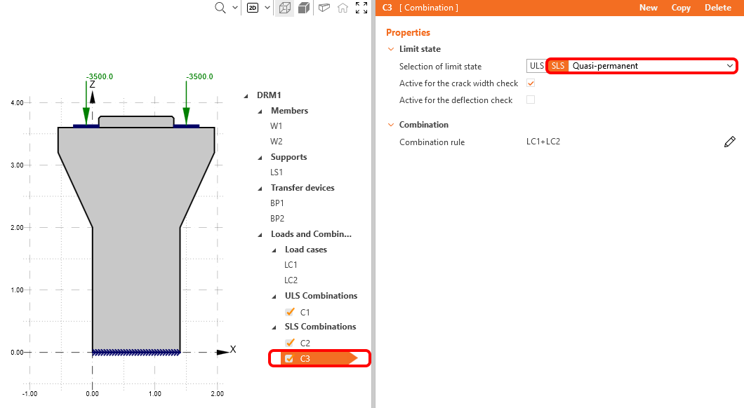
Now you can repeat the steps, copy C2 and choose SLS Quasi-Permanent for new C3. Activate Quasi-Permanent combination only for crack width calculation.
Now, change the partial factors for all combinations. To do that, click on the pen icon in any combination you defined and change the partial factors you see in the following picture.
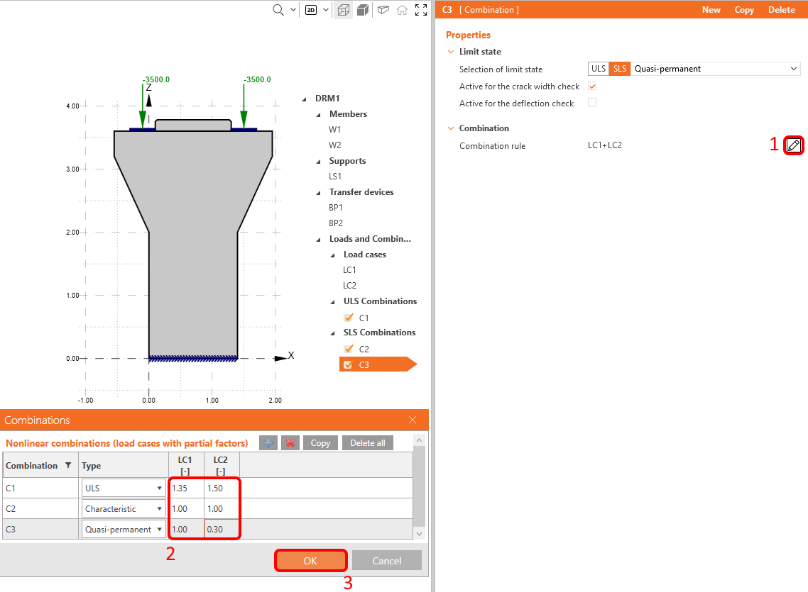
Note that the calculations are performed only for combinations of load cases that are ticked in the operation tree, not for individual load cases.
4 Reinforcement
The next step is to reinforce the model. Combine the definition from scratch in IDEA StatiCa with the batch import of the reinforcement from the DXF file. In this tutorial, we assume that the user knows how to reinforce a pier cap and prepared some reinforcement in DXF in advance from drawings thus, we leave the tools for reinforcement design for another tutorial.
Click on DXF Import and choose Group of bars entity.
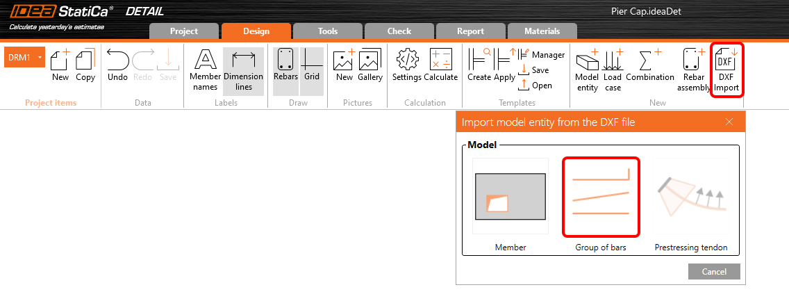
A dialog to locate and open the desired DXF file will pop-up. After the selection of pier_cap.dxf (available in the source files), you will land in a dialog for selection. Select all the polylines (rebars shape) you need in order shown on the following picture and click on Select after each polyline (the order is not important in general, we just want to keep track in this tutorial when we talk about the specific name of an item). Finish the selection by OK button.

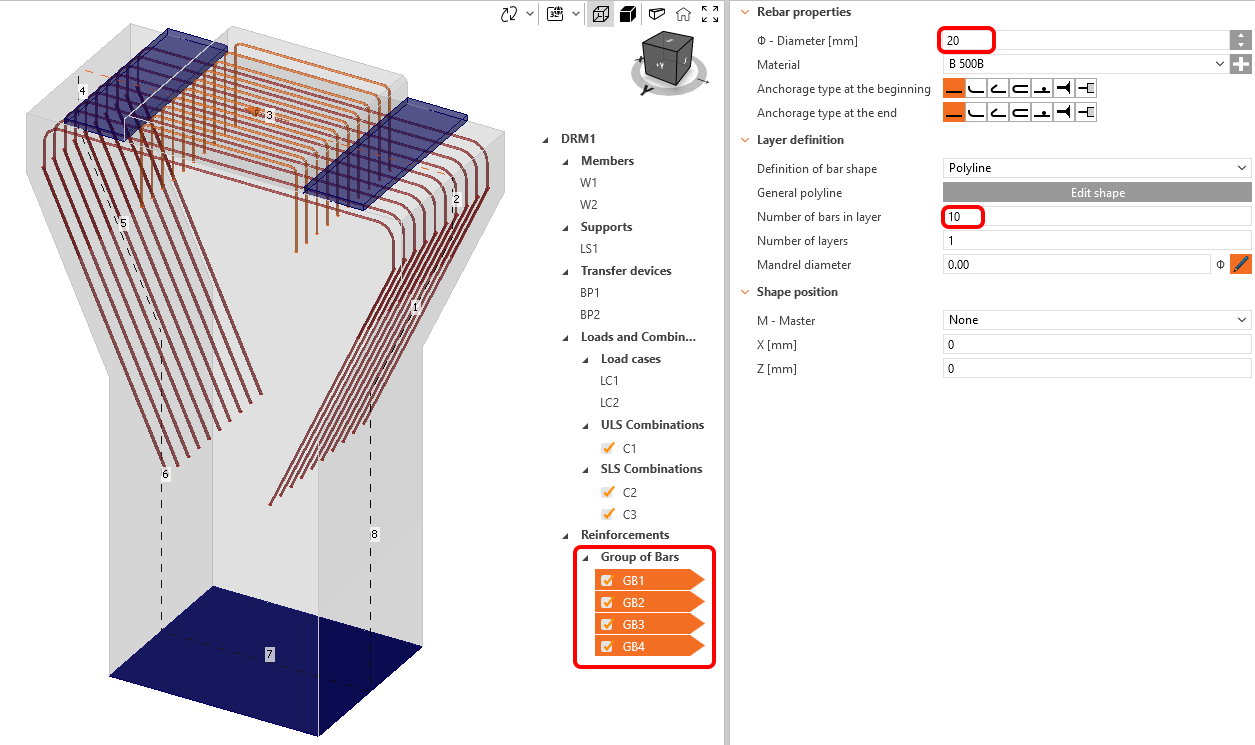
The 2D DXF file transfers the global width of a polyline as the diameter for each rebar, but it does not contain information about the number of bars in the perpendicular direction, and we need to adjust them manually. Thanks to the multi-editing feature, we can provide all changes for all reinforcement entities at once.
Hold Ctrl and select all imported reinforcement, change the number of bars in a layer 10 and diameter to 20 mm.
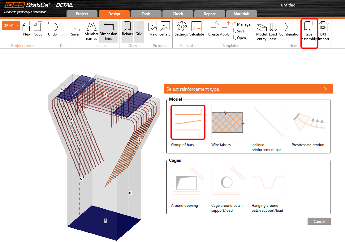
To finish the reinforcement in this example, combine the reference from DXF with reinforcement defined in IDEA StatiCa Detail. In this case, add some horizontal and longitudinal reinforcement into the pier cap and a few layers of reinforcement representing the stirrups in the pier. Click on the Rebar assembly button and select the first reinforcement item Group of bars.
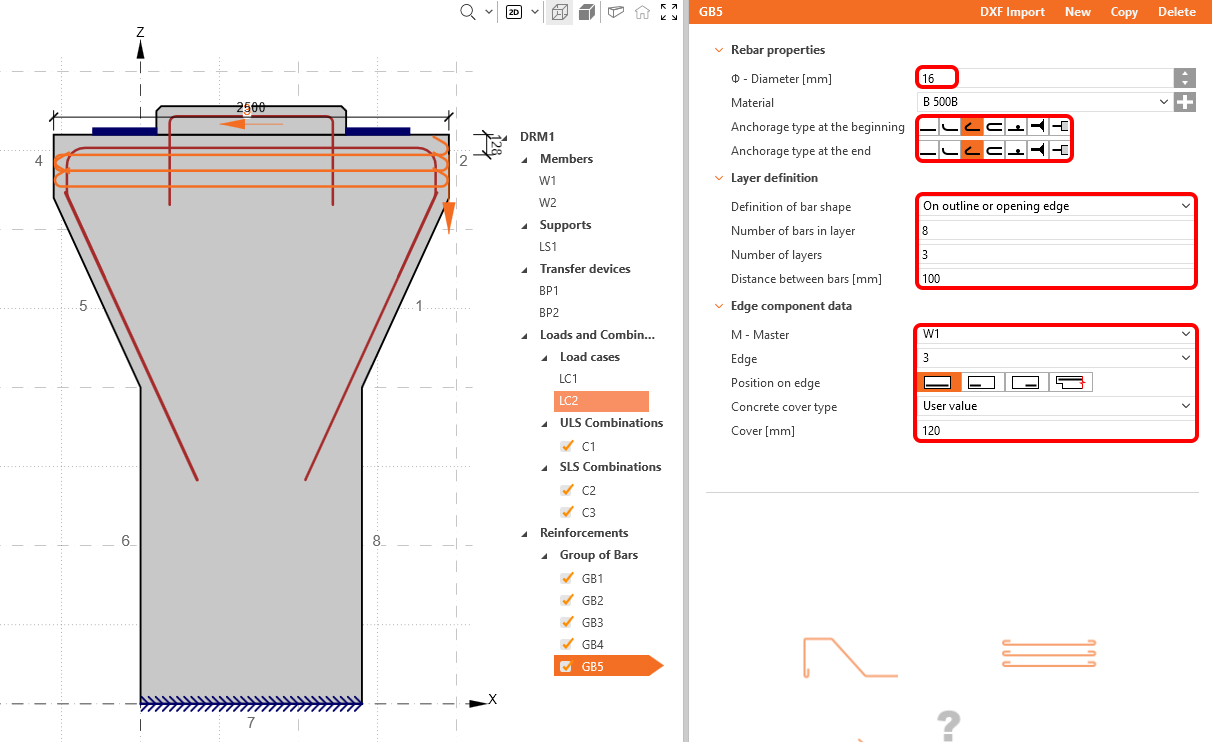
Change the definition to On outline or opening edge. Then adjust the number of layers, their distances, the diameter, the number of bars in a layer, anchorage type for both ends and edges according to the following picture:
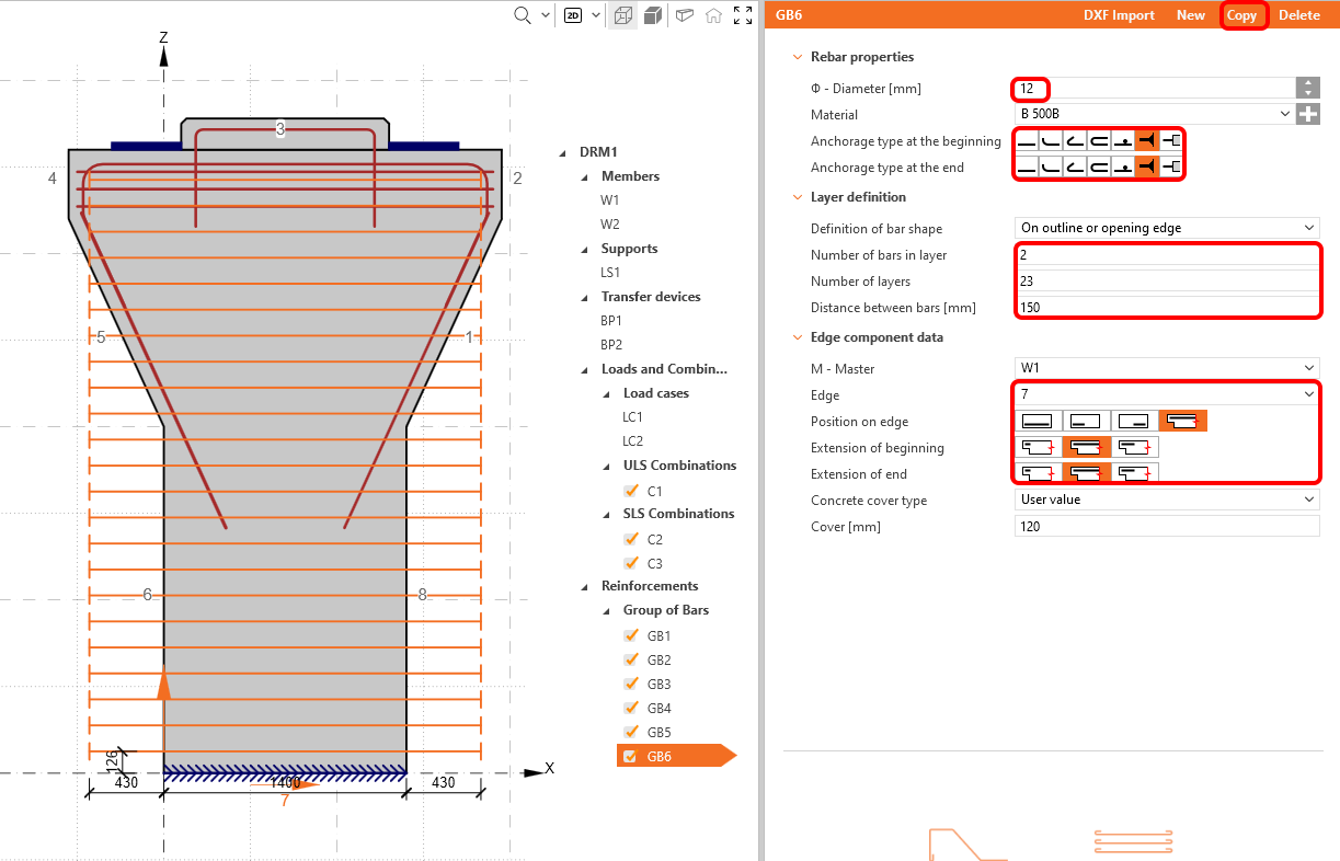
Use the copy function to create GB6, which will represent the stirrups, and switch the edge to 7. Set all parameters according to the picture below:
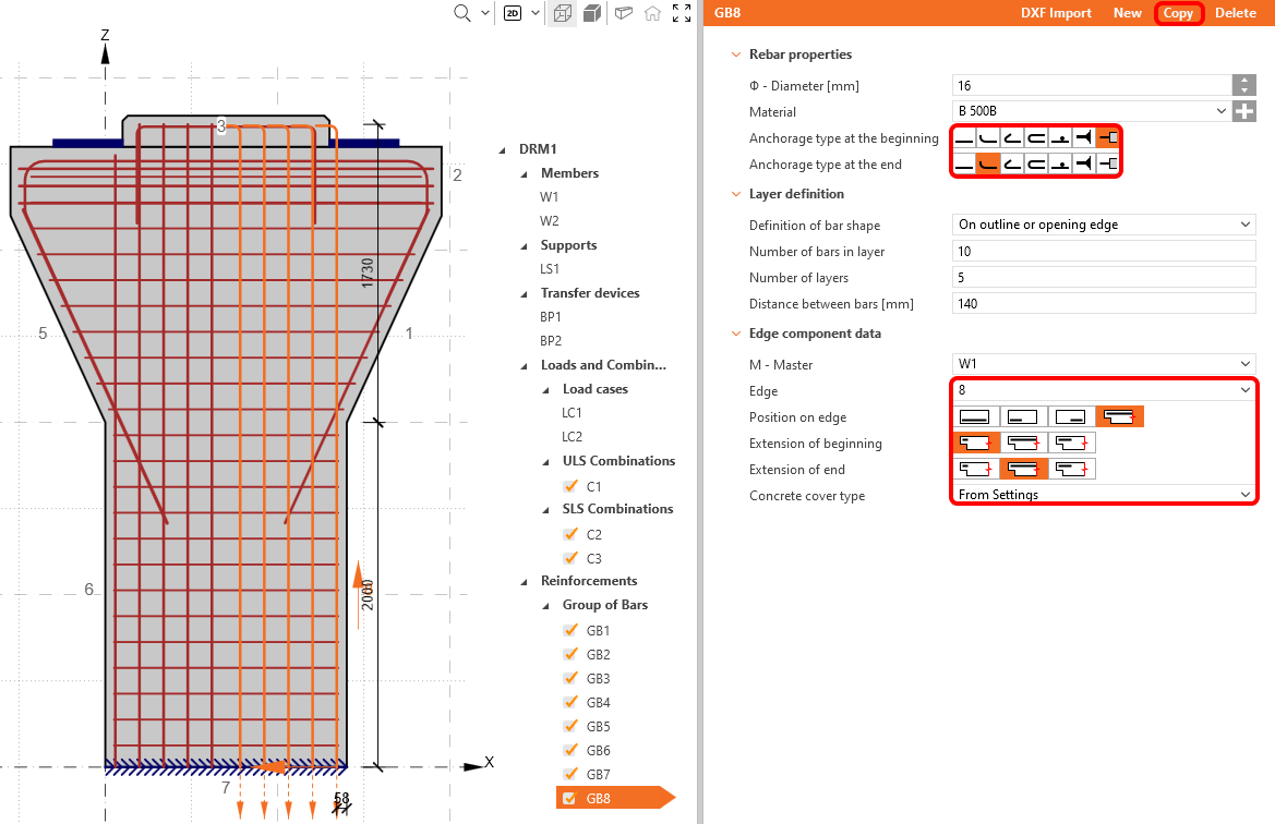
The last reinforcement items will introduce the longitudinal reinforcement of the pier cap. To do that, add a new group of bars. Change the properties as follows:
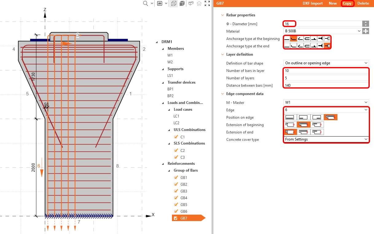
Use the copy button for the last time. Change the edge to 8.
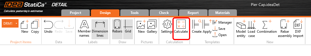
After all reinforcement added and edited we can start the calculation by clicking on Calculate button.
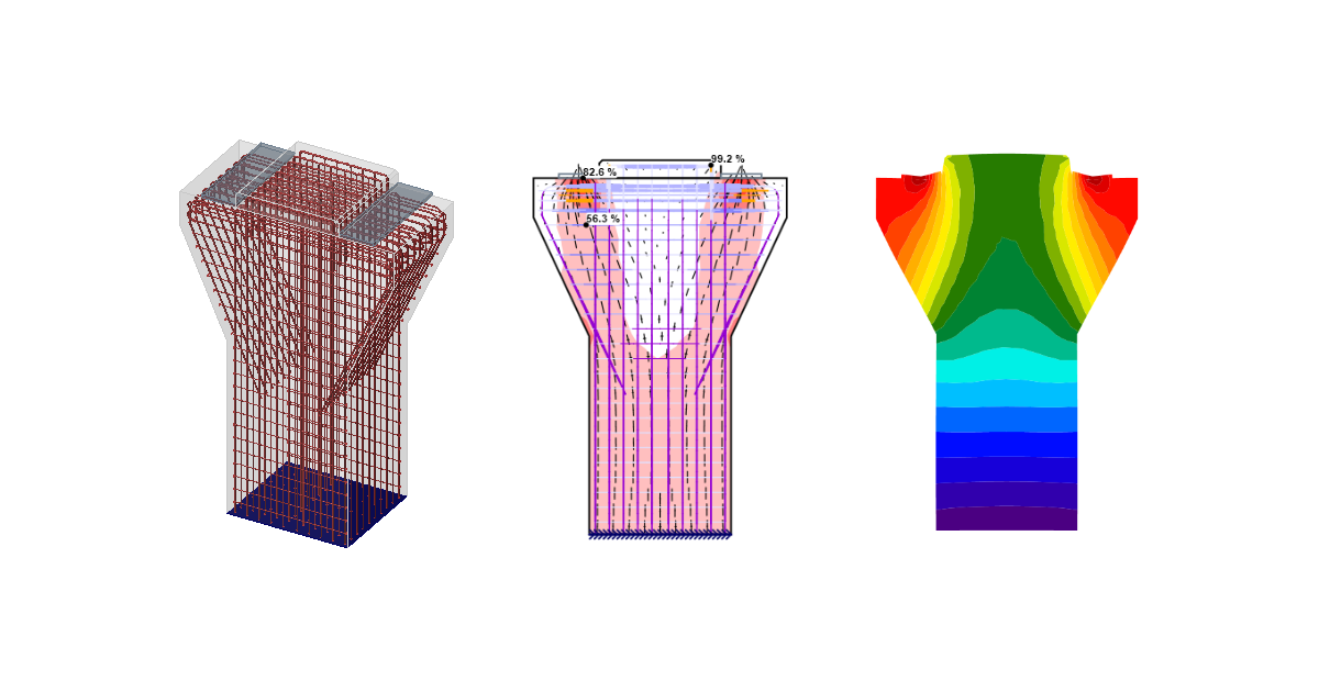
5 Calculation and Check
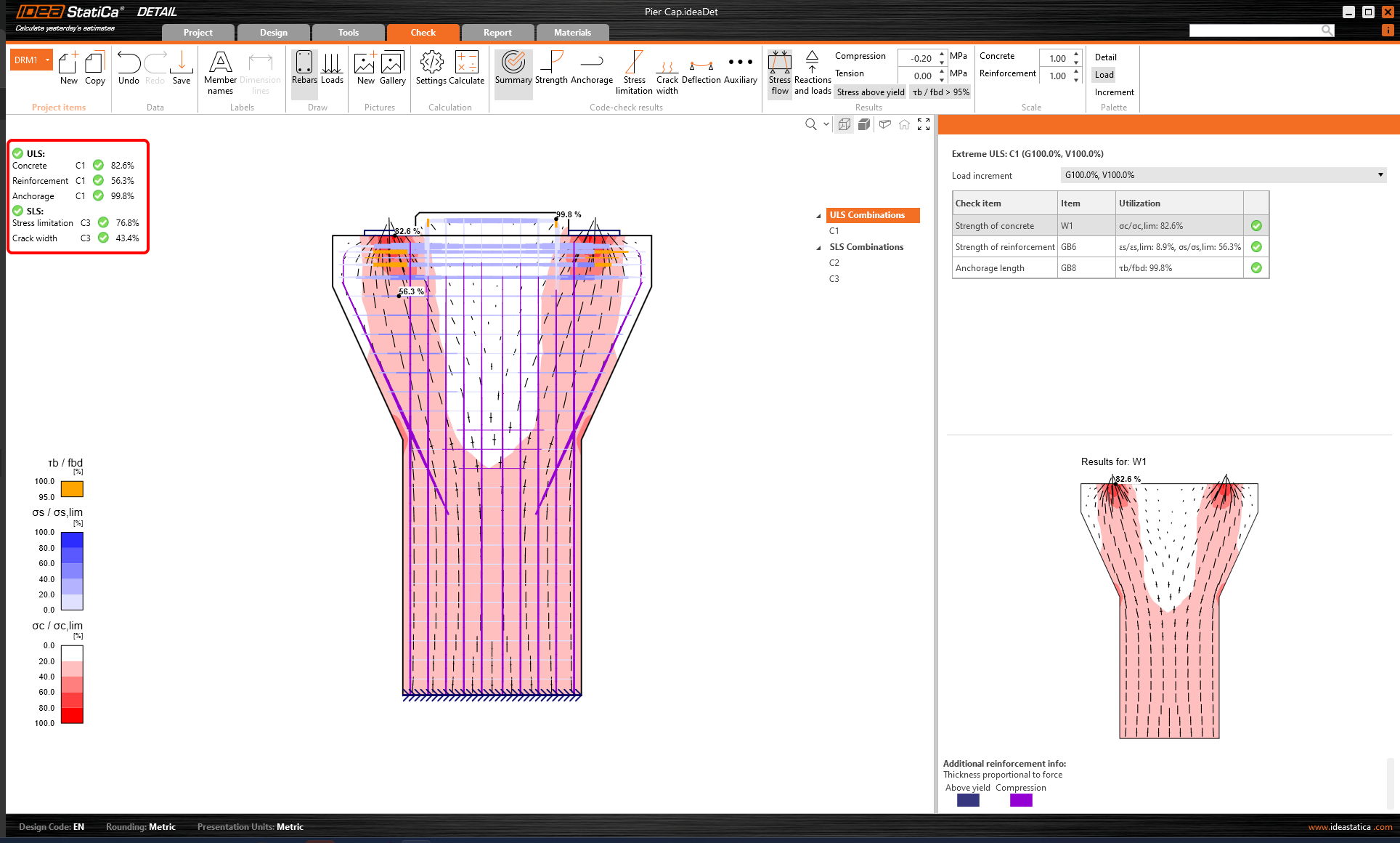
Start the analysis by clicking Calculation in the ribbon. The analysis model is automatically generated, the calculations are performed and you can see the summary of checks displayed together with the values of check results.
To go through the detailed checks of each component, start with the Strength tab. This will show concrete checks such as utilization in stress, principal stresses, strains, and a map of reduction factor kc, which can be switched on the ribbon.
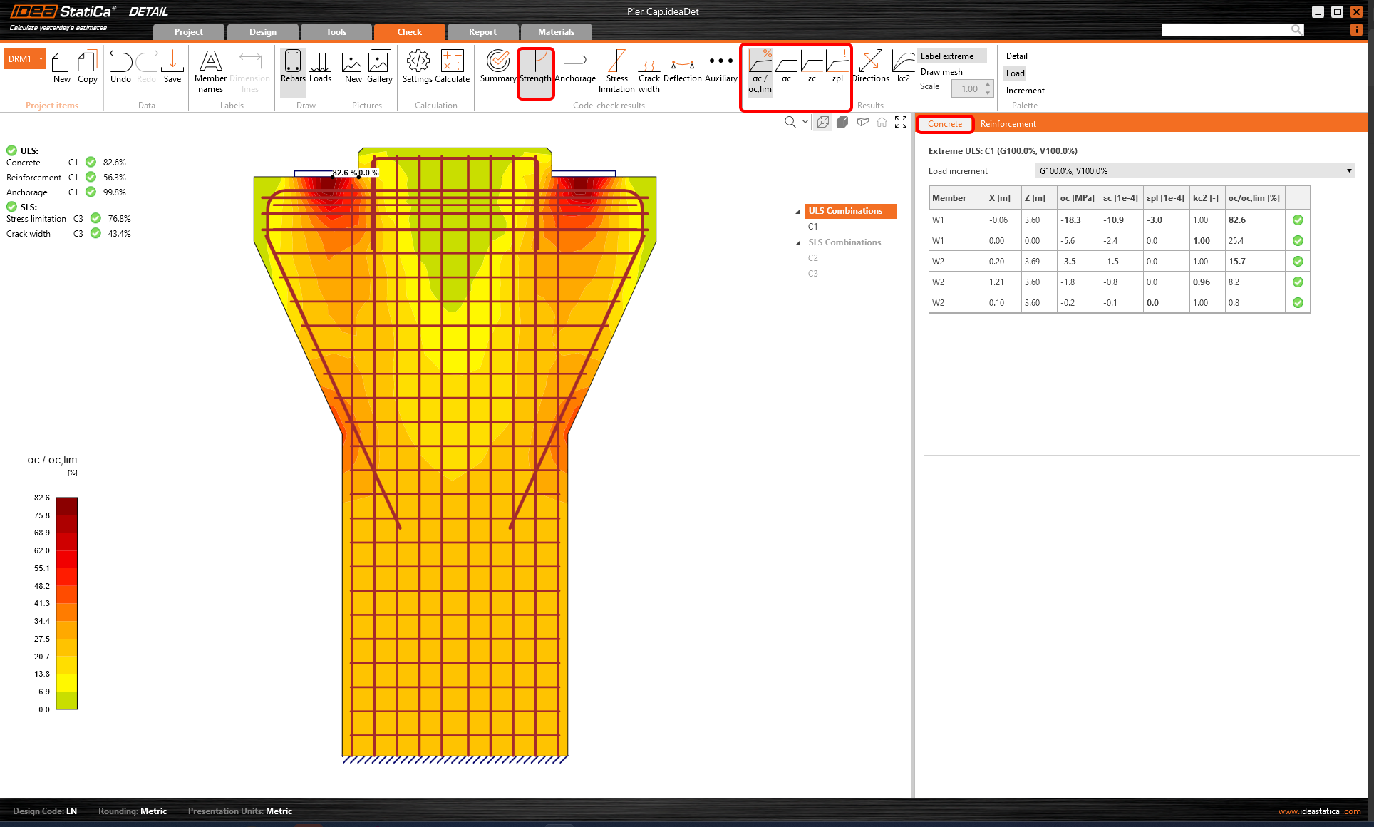
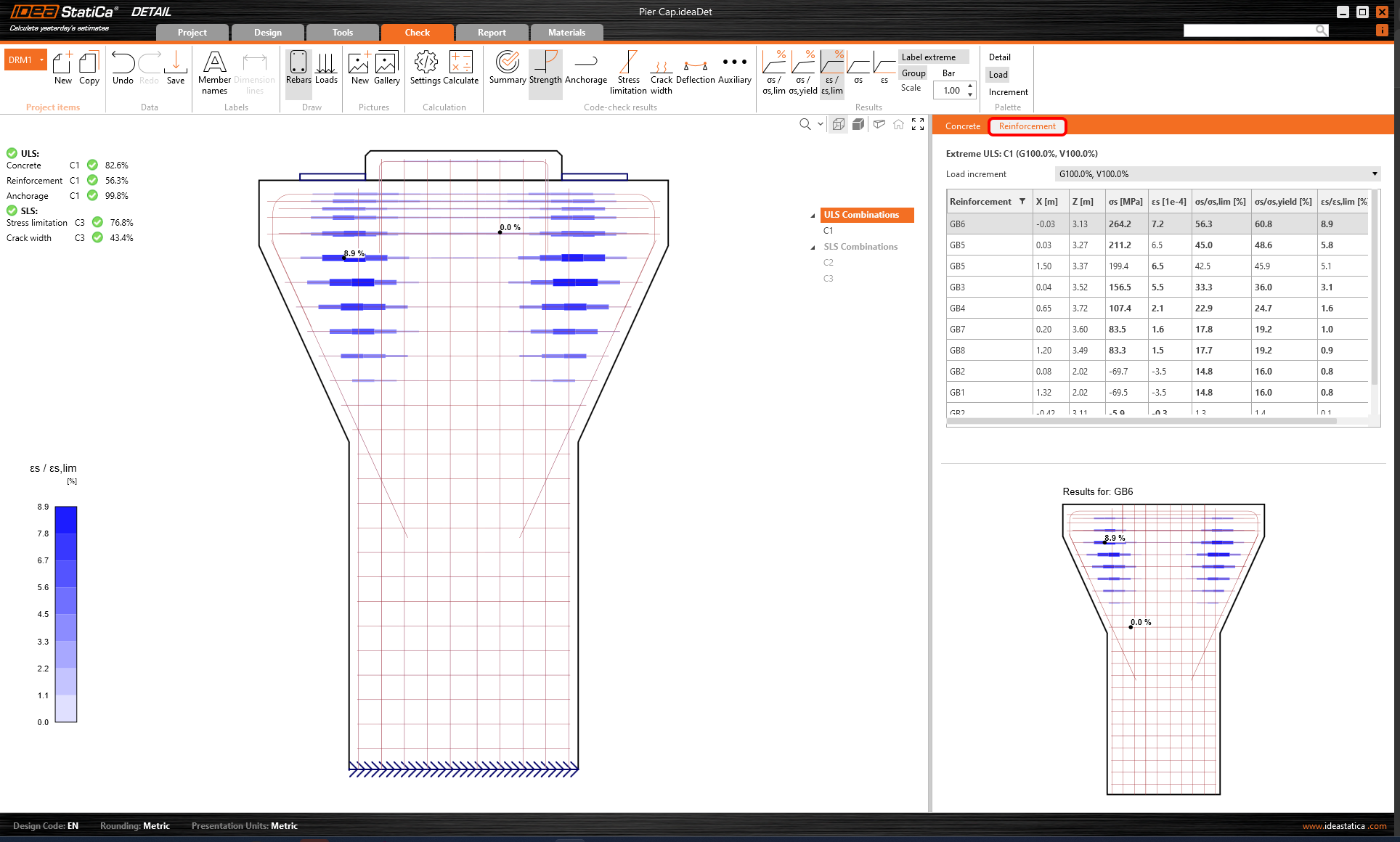
For detailed results of reinforcement, you need to click on the row Reinforcement. This will change the ribbon icons and unroll the table for results. You can display the results for strains and stresses in each bar and their utilization.
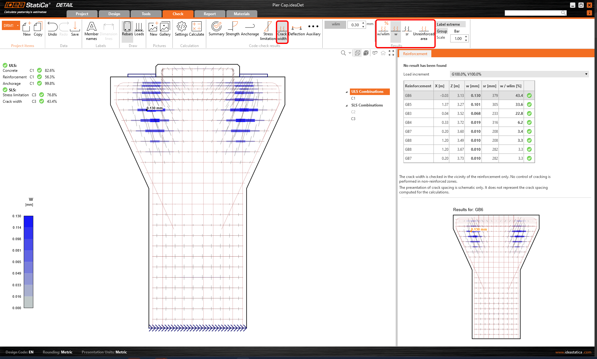
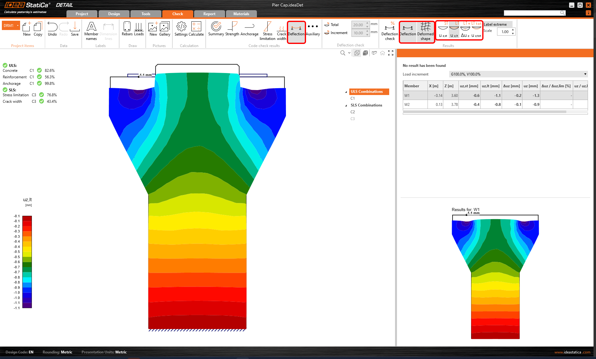
All results can be displayed in the same way. Let´s show the difference in the ribbon for SLS checks of crack-width and deflection. Besides the icons to switch between the results, there are settings in the ribbon to set the limit value of cracks or to display the results of deflections from short/long-term models.
6 Report
At last, go to the Report. IDEA StatiCa offers a fully customizable report to print out or save in an editable format.
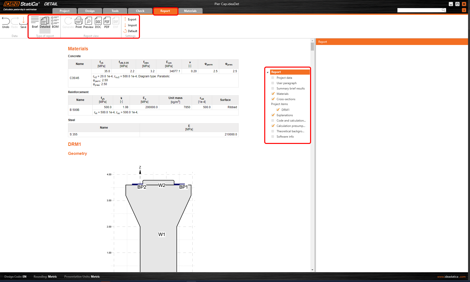
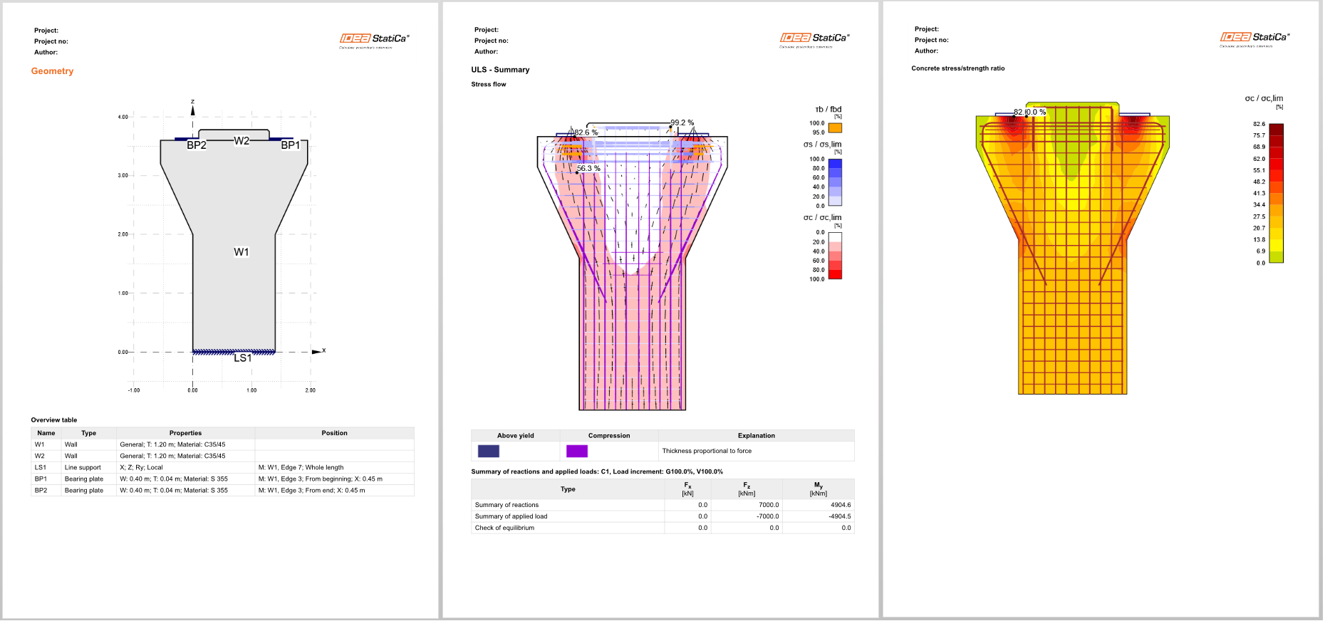
You have designed, optimized, and code-checked a pier cap according to Eurocode.