Reinforcement definition in the Detail application
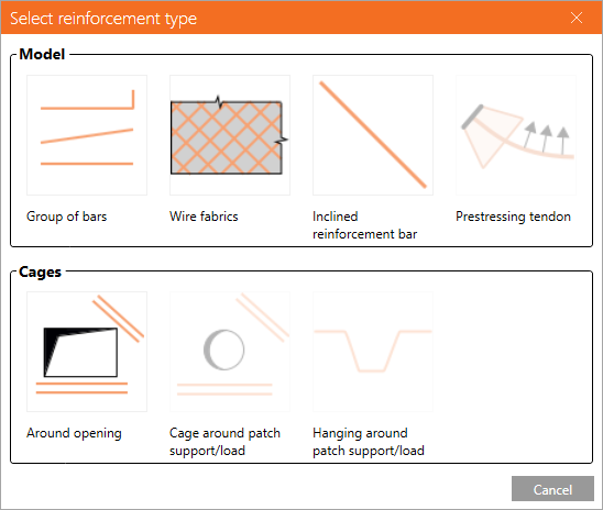
There are several predefined reinforcement types for the reinforced concrete wall elements:
- Group of bars
- Wire fabrics
- Inclinated reinforcement bar
- Cage around opening
- Cage around patch support/load
- Hanging around patch support/load
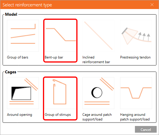
And some additional types specially for the reinforced concrete beam elements:
- Bent-up bars
- Group of stirrups
For a better understanding what is the difference between wall and beam elements, see the article Geometry types in Detail.
Now, let's take a closer look at the types individually.
Group of bars
Definition of the bars & shape
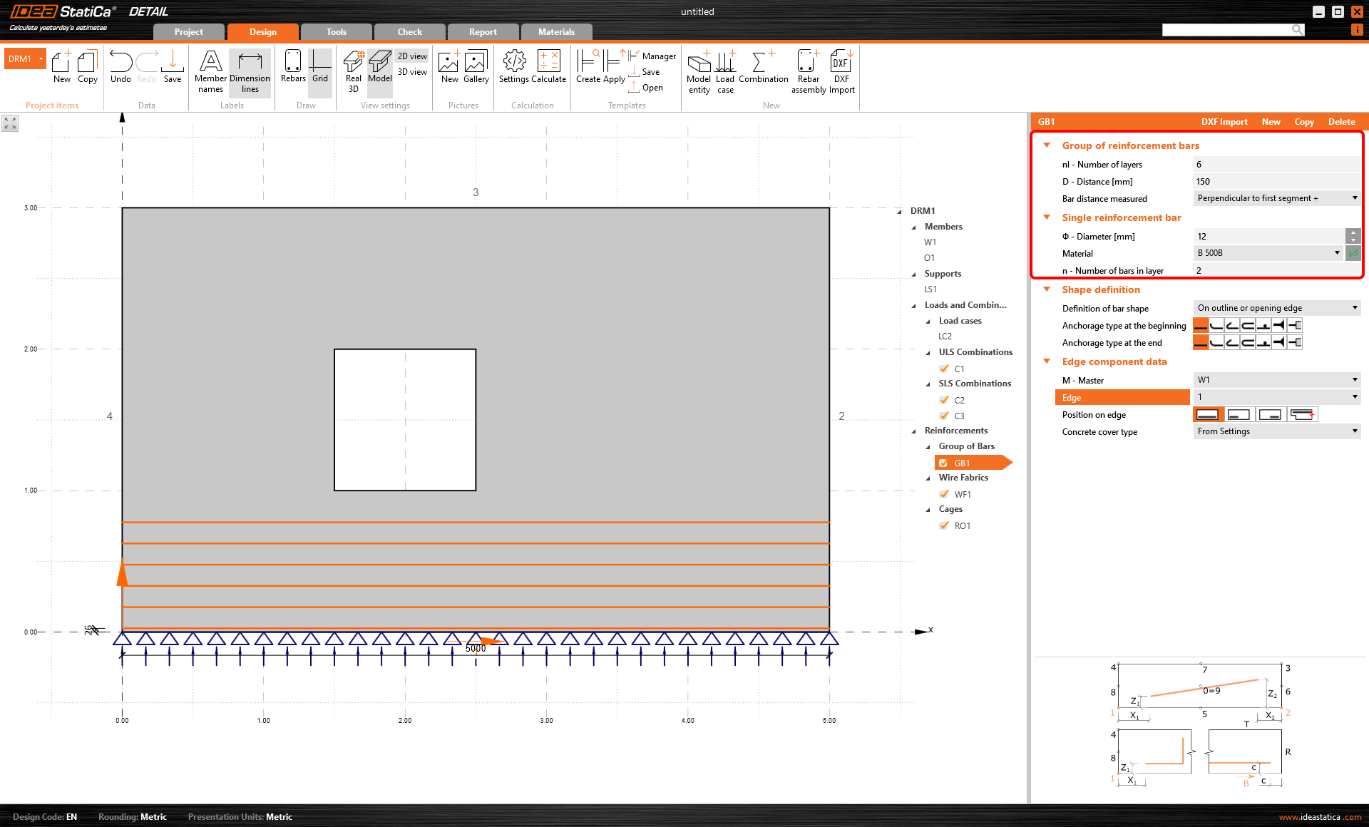
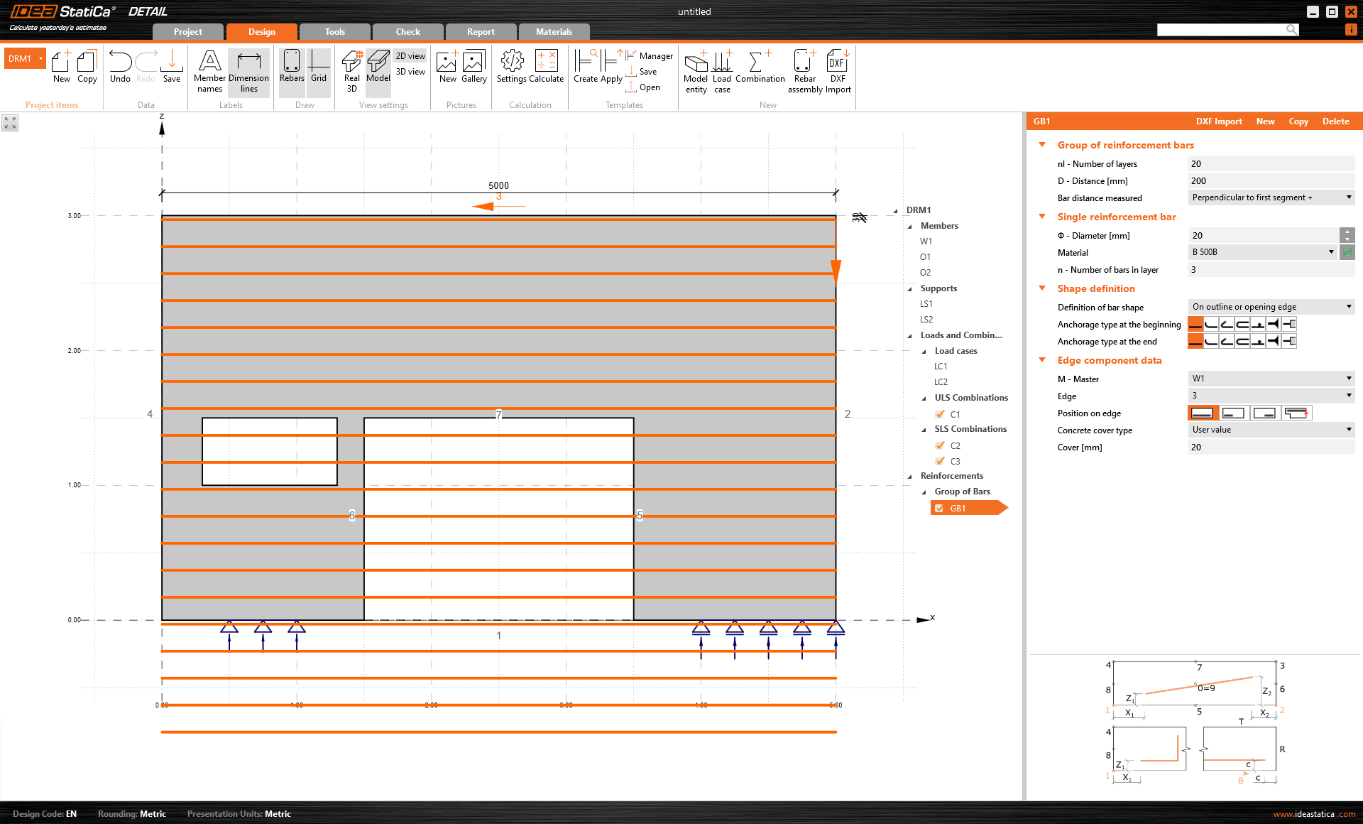
Using this entity, you have to set the reinforcement bar's diameter, the number of bars in a layer (out-of-plane direction), the number of layers (in-plane direction), and the distance between layers. See the following figure where the settings are shown.
The definition of the bars' shape is important for the anchorage check. It can be done:
- By two points
- On outline or opening edge
- On more edges
- By polyline
Using these options can help you with the definition of the various shapes of the bars. See the practical examples below.
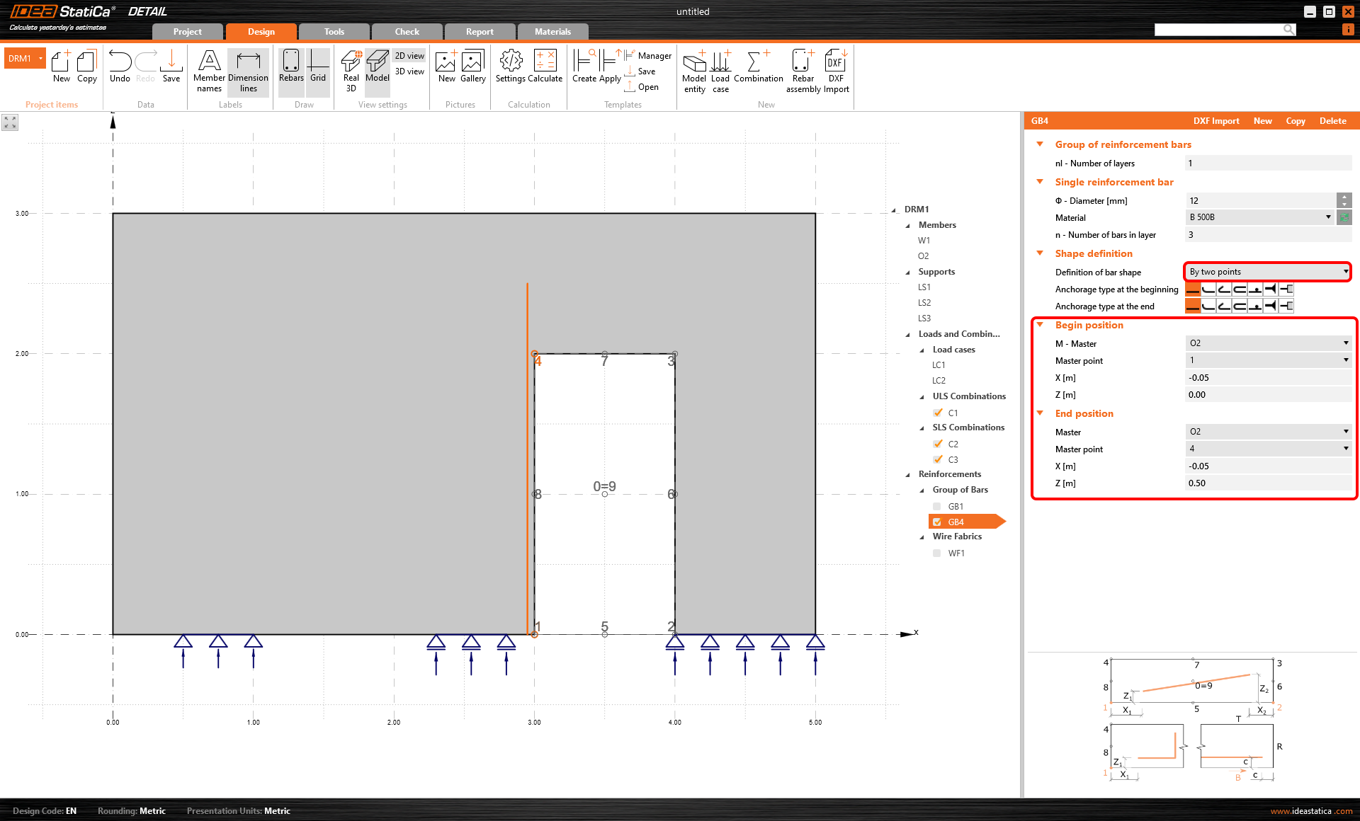
\[ \textsf{\textit{\footnotesize{Reinforcement defined by two points}}}\]
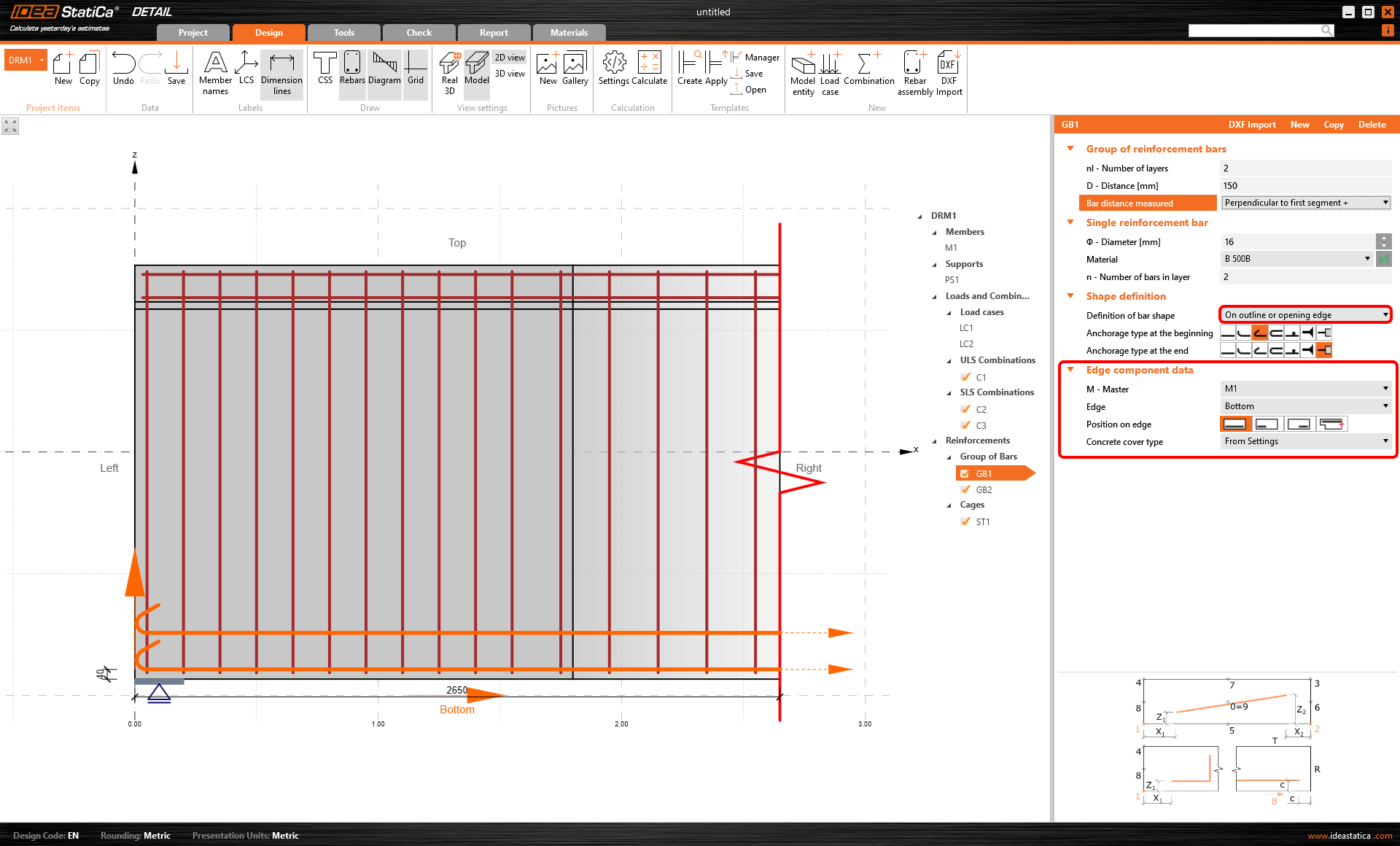
\[ \textsf{\textit{\footnotesize{Reinforcement defined on outline or opening edge}}}\]
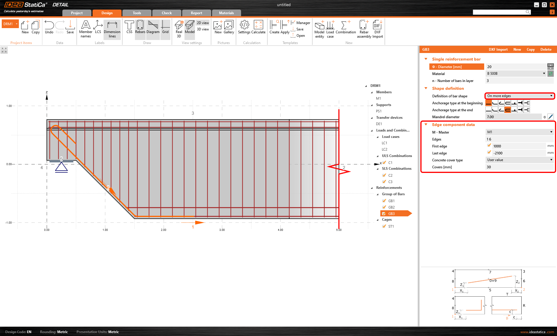
\[ \textsf{\textit{\footnotesize{Reinforcement defined on more edges}}}\]
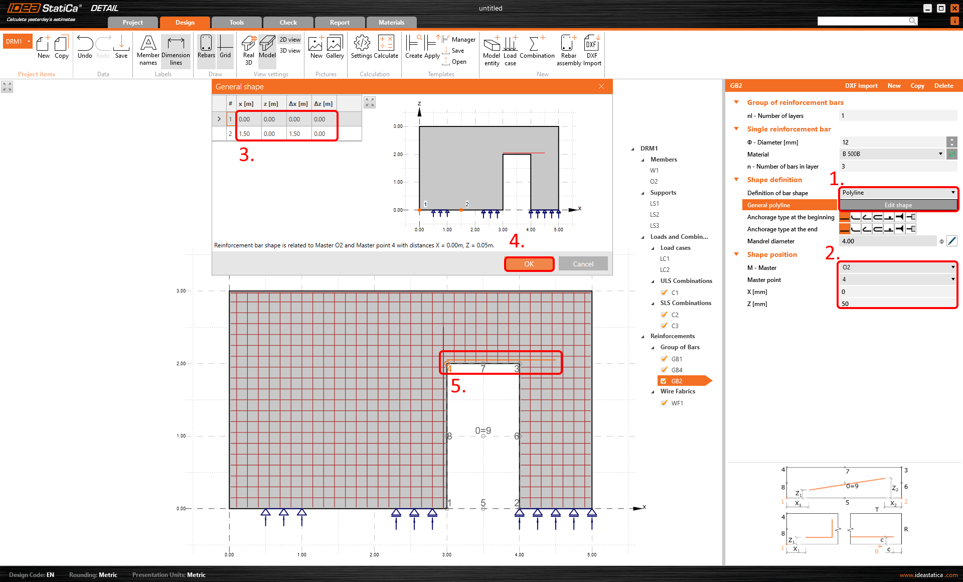
\[ \textsf{\textit{\footnotesize{Reinforcement defined by polyline}}}\]
Setting the proper anchorage type is essential for the design. Learn more about it in the article Finite element types.
Position on edge
When defining the group of bars on the outline or opening edge, there are four ways to set the position:
- Whole length
- Part edge from beginning
- Part edge from end
- Whole length and extension
Moreover, the last option - Whole length and extension has three possibilities of settings:
- No extension
- Extended up to outer edge
- Extended by length
For a better explanation, all options are shown in the images below.
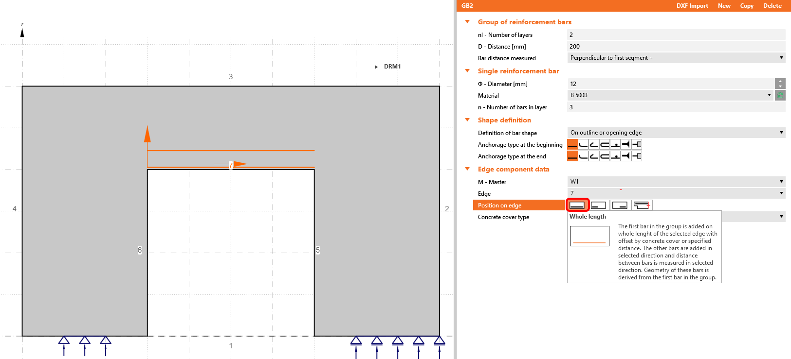
\[ \textsf{\textit{\footnotesize{Whole length}}}\]
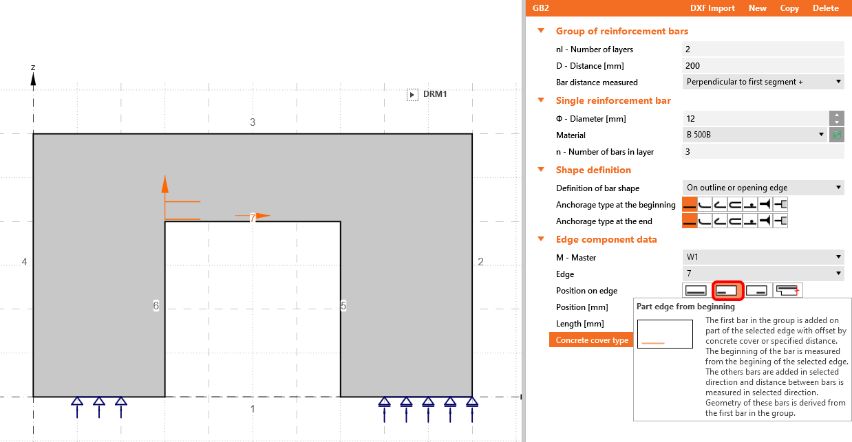
\[ \textsf{\textit{\footnotesize{Part edge from beginning}}}\]
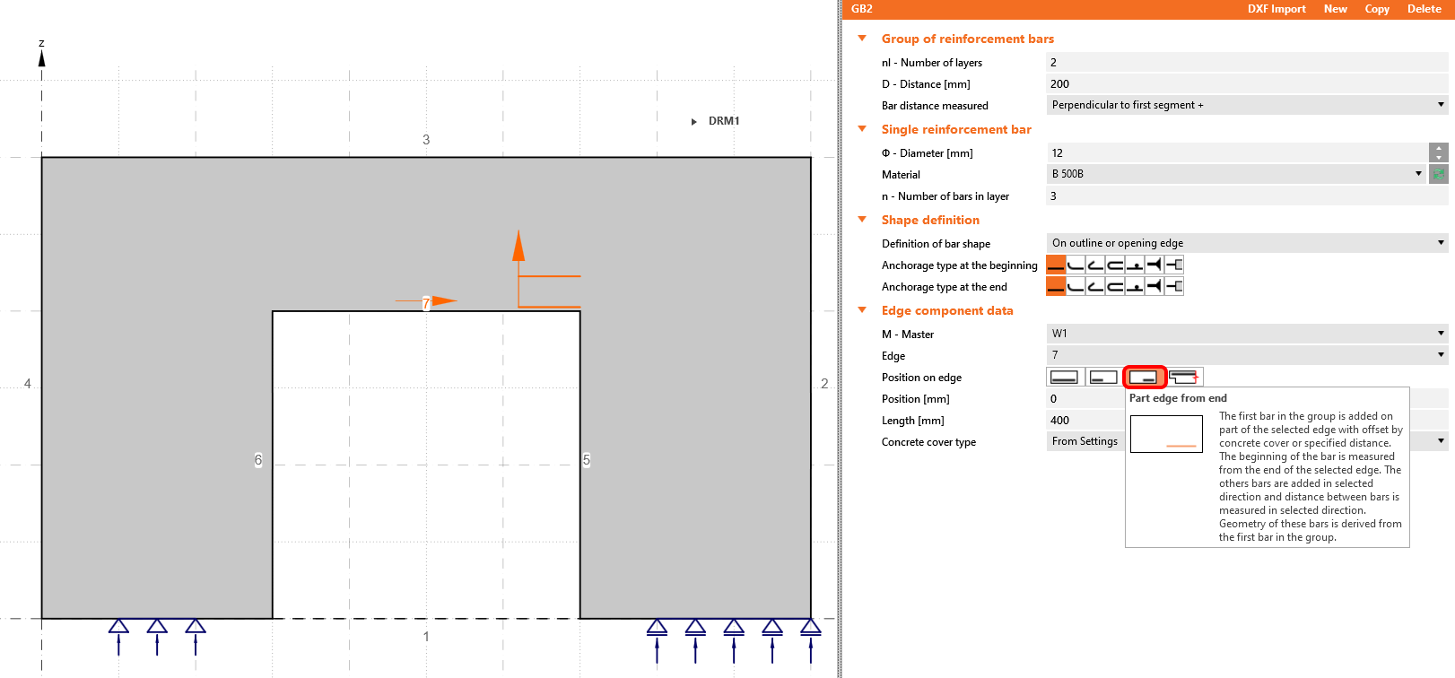
\[ \textsf{\textit{\footnotesize{Part edge from end}}}\]
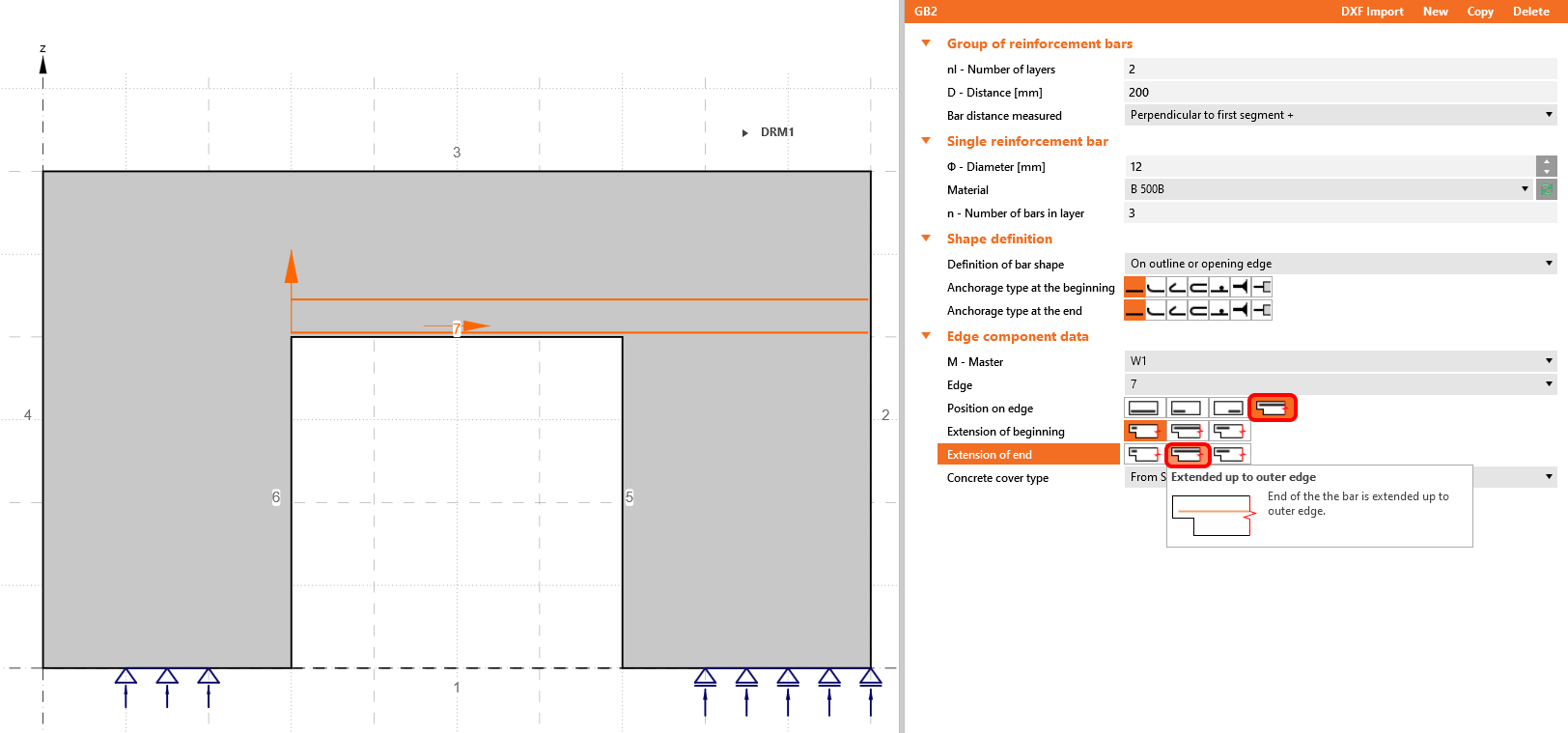
\[ \textsf{\textit{\footnotesize{Extended up to outer edge}}}\]
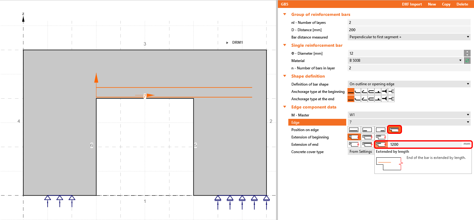
\[ \textsf{\textit{\footnotesize{Extended by length}}}\]
A group of bars can be applied for all types of geometry. The best way to understand all of the options and possibilities is to open the application and try the different approaches on practical examples. It's easier than it seems!
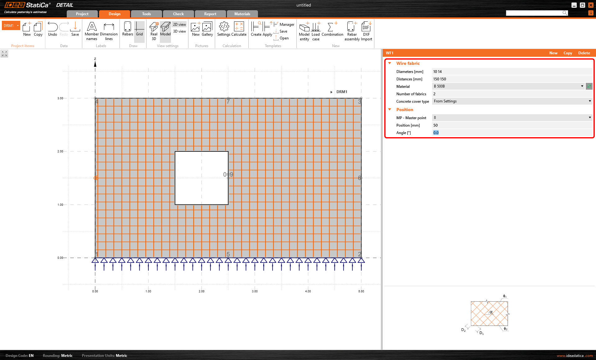
Wire fabric
Using the wire fabric might help you model the reinforcement faster than defining it using the group of bars. Nevertheless, be aware that it can be applied only to the wall elements in the project.
The diameters and distances between bars can be set individually for both directions. You can define the position using the master point and coordinates, and last but not least, the reinforcement inclination.
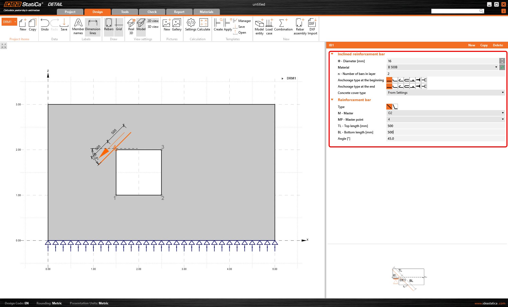
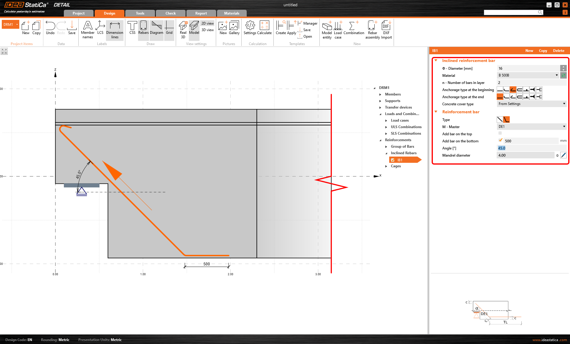
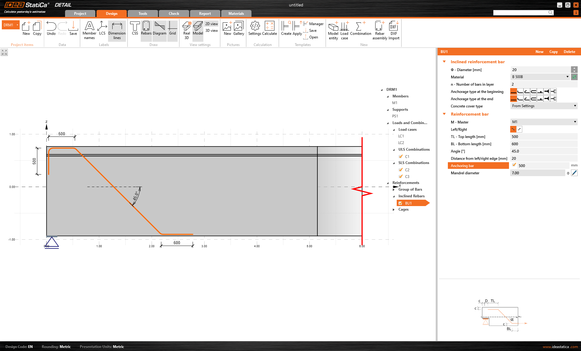
Inclined reinforcement bar
Usage of the inclined bars might help you model the reinforcement faster than defining each bar on more edges of the element.
For the wall elements, inclined bars can be applied only around the openings. You need to define several parameters.
The first part is to define the bar shape - the software distinguishes two types - a straight bar defined by two points, or a bend-up bar.
Then you need to define the master element - in this case, the opening. And continue with the master point, the bar's length, and last but not least, the angle.
When you're modeling a structure using the beam element, the inclined bars definition is available only for structures with dapped ends or openings. The conditions are basically the same as for the walls.
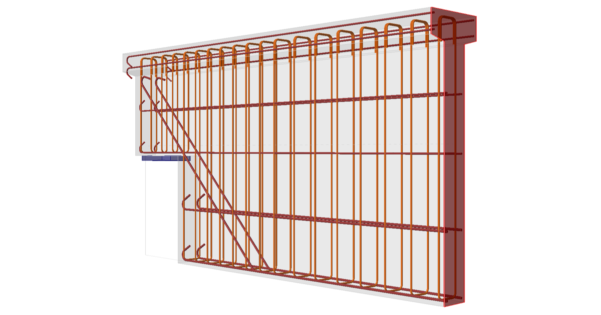
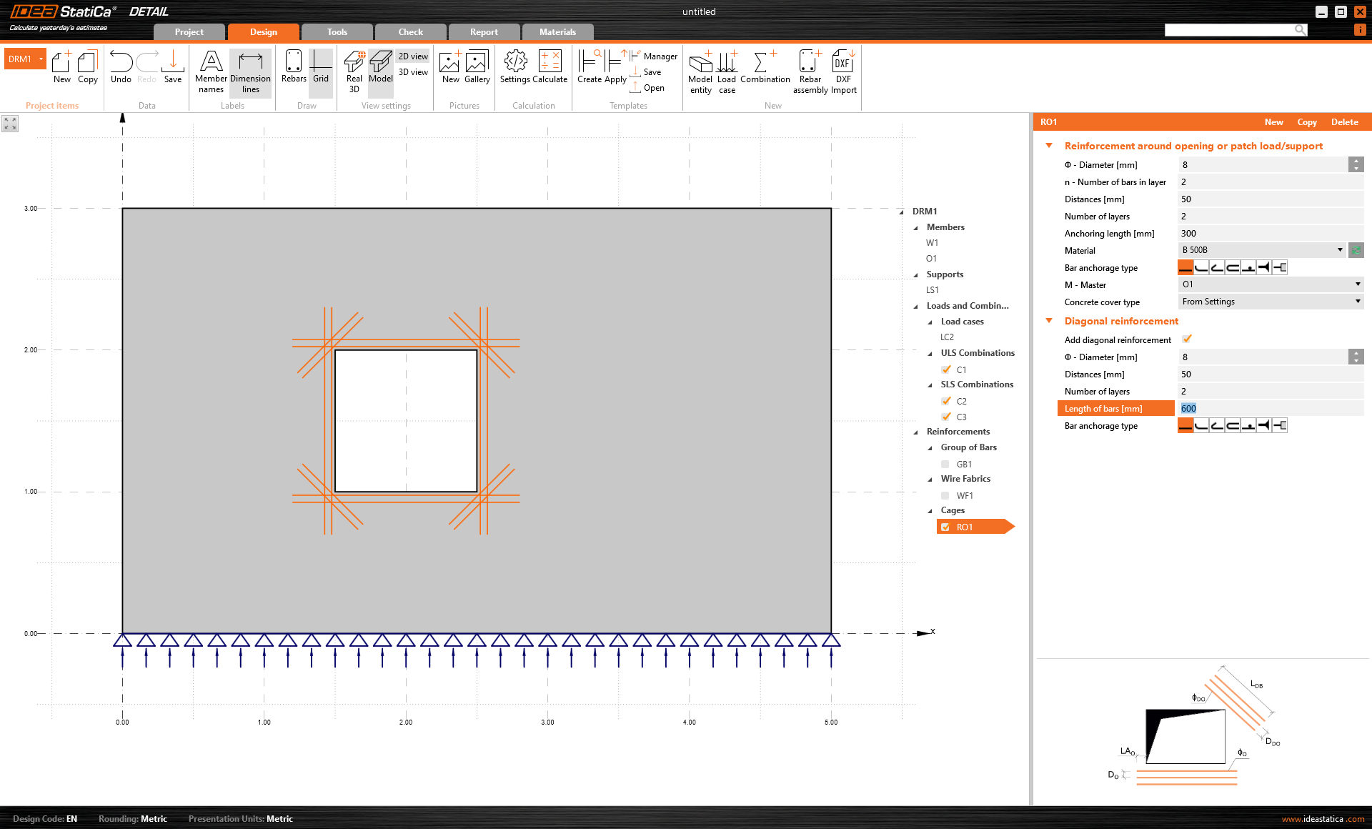
Cages around opening
Cages around opening can be defined for every opening, including an opening defined by the polygon for every type of structure. Again, you need to set all the basic parameters. See a practical example in the image below.
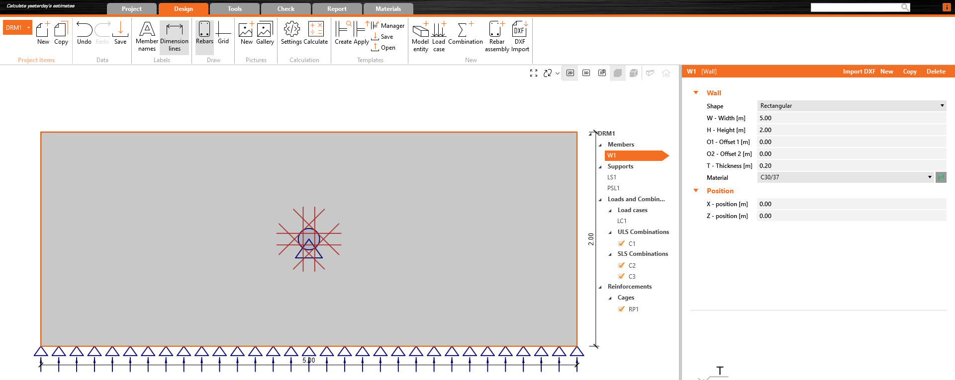
Cages around patch support/load
This predefined type of reinforcement is the same as a cage around a circular opening.
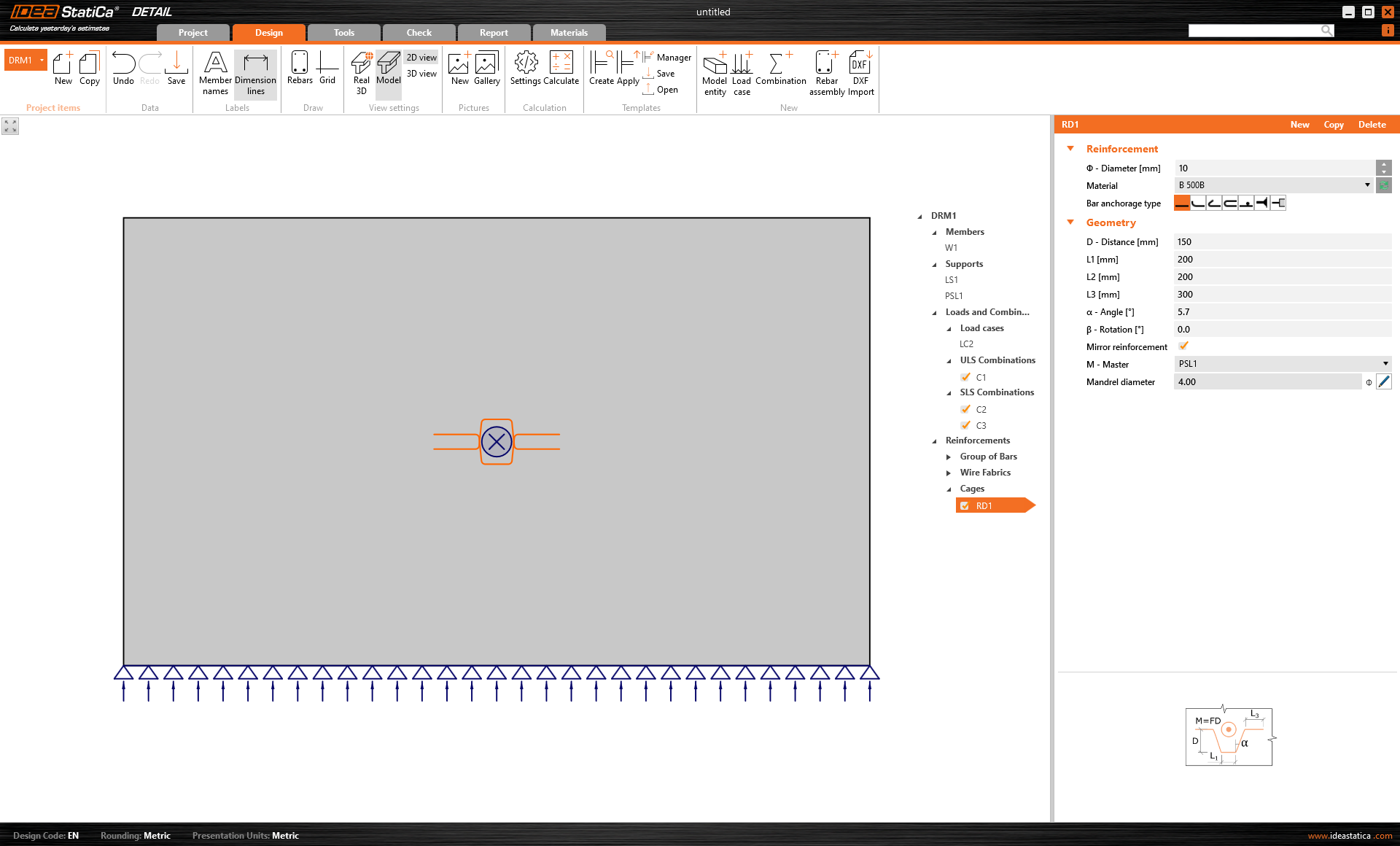
Hanging around patch support/load
This type of reinforcement offers you to use a predefined typical shape of the reinforcement.
Bent-up-bars
Inclined bars like this are commonly used to resist shear instead of stirrups. Their angle makes them more effective than stirrups. The Bent-up-bars can be applied only to beam types of geometry.
You can see the necessary settings in the image below.
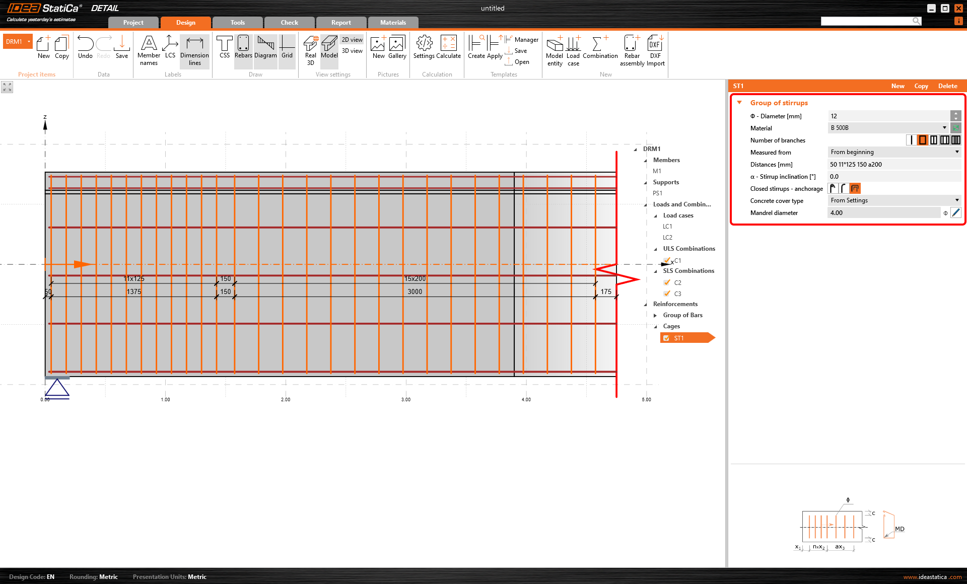
Group of stirrups
The stirrups can be modeled only in structures with beam elements. As for any other reinforcement, you have to set the necessary parameters.
You can define how many branches the stirrup will have - whether it is one-legged, two-legged, and so on. Furthermore, it's important to set the correct distance between the stirrups. There are several ways how to do it. See the example in the following image.
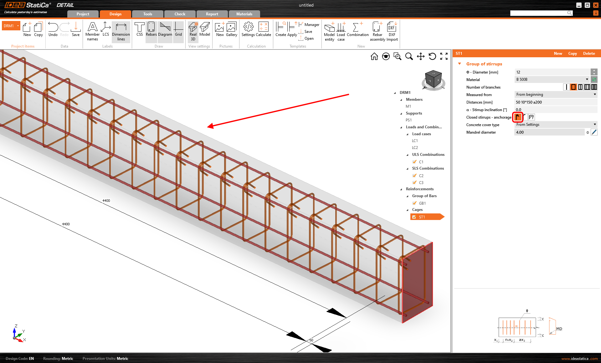
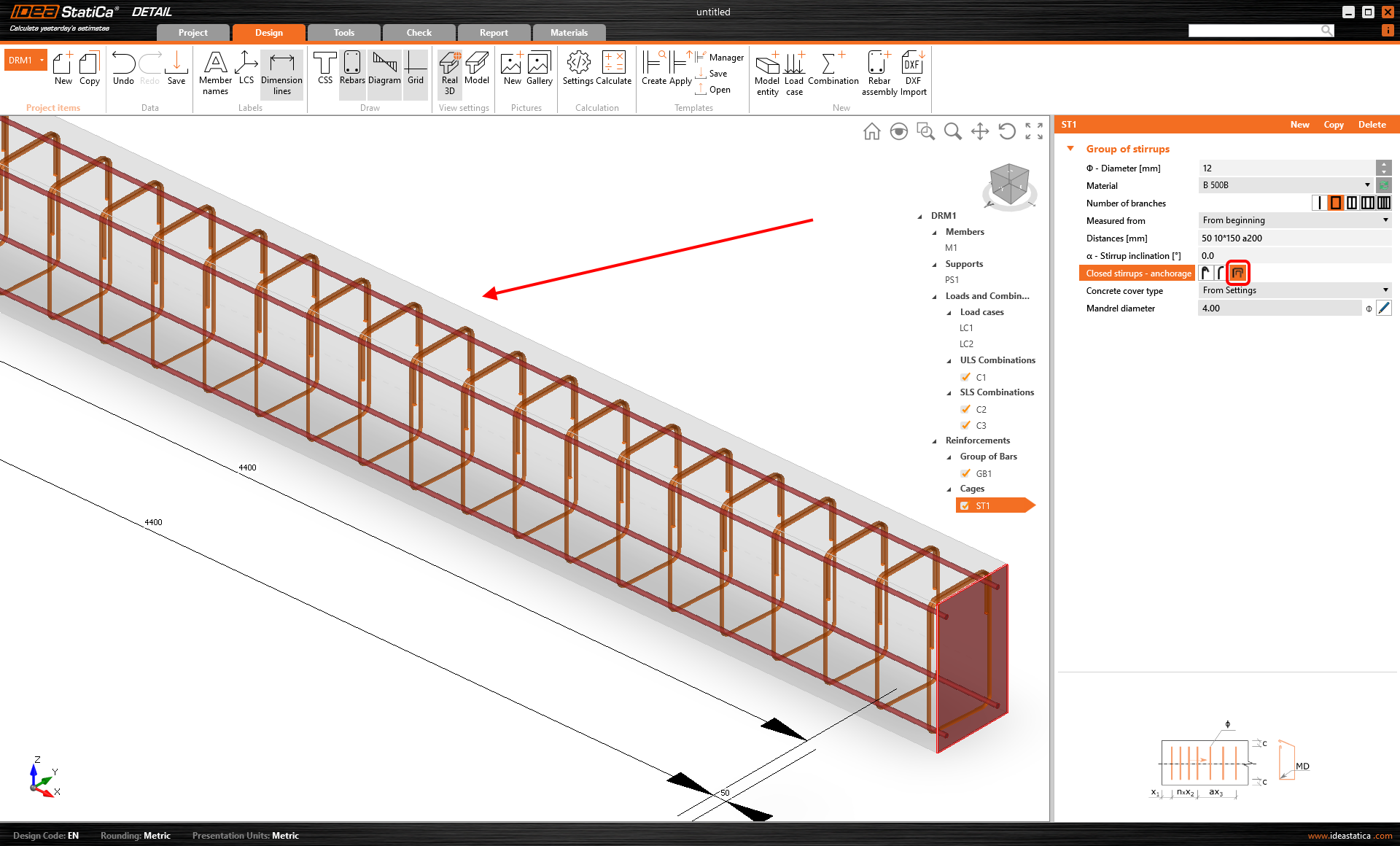
The last important part is to define the anchorage of the stirrups. The software offers three options:
- Stirrups with standard hook
- Stirrups with standard bend
- Closed stirrups with overlapped branches
\[ \textsf{\textit{\footnotesize{Standard hook}}}\]

\[ \textsf{\textit{\footnotesize{Standard bend}}}\]
\[ \textsf{\textit{\footnotesize{Overlapped branches}}}\]
For the individual definition of the anchorage types, read the article Finite element types.
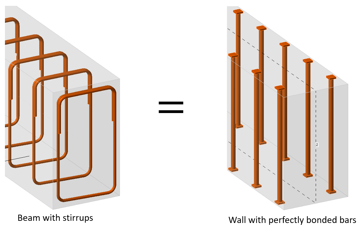
As you already know, stirrups can be applied only to structures modeled with beams. However, it is possible to simulate them in other elements using a group of bars with corresponding anchorage type. See the example of closed stirrups modeled in the wall using a group of bars with a perfect bond at the ends.
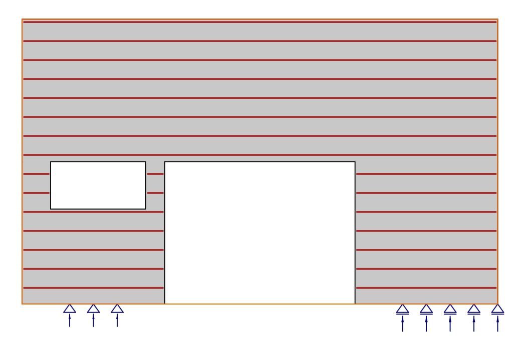
Final note - if you model reinforcement through the opening or over the edges, the bars will be automatically cut by the software. In the first figure, you can see the definition of the group of bars.
In the second figure, the reinforcement is cut.