

Overview of the analyses
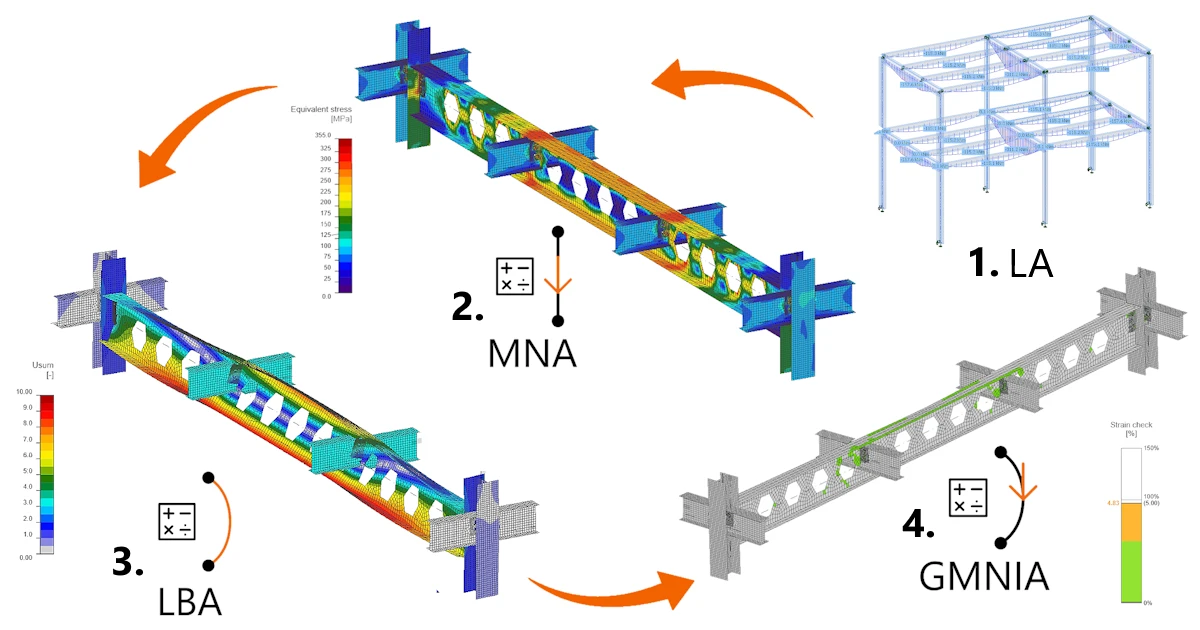
The following four analyses are included in the IDEA StatiCa Stability workflow:
- LA – linear analysis of the model consisting of 1D beam elements only (NEW in Stability)
- MNA – materially nonlinear analysis of the analyzed part of the structure, modeled using CBFEM
- LBA – linear buckling analysis to determine the eigenmodes used to define imperfections
- GMNIA – geometrically and materially nonlinear analysis with imperfections, which checks the analyzed part of the structure modeled using CBFEM, including the effects of potential loss of stability
Each analysis uses the result of the previous one, so they run in a fixed order.
| Step / Analysis | Model | Material | Geometry | Main output |
| 1LA | 1D beam elements, whole model | Linear elastic | 1st order calculation | Internal forces, reactions, deformations |
| 2MNA | Analyzed part by CBFEM | Elastic-plastic | 1st order calculation | Strength check (check of the maximum plastic strain) |
| 3LBA | Analyzed part by CBFEM | Linear elastic | Eigenvalue problem | αcr, buckling mode shapes |
| 4GMNIA | Analyzed part by CBFEM + imperfections | Elastic-plastic | 2nd order calculation | Strength check including the effects of loss of stability (check of the maximum plastic strain) |
1. Linear analysis on the 1D beam elements model
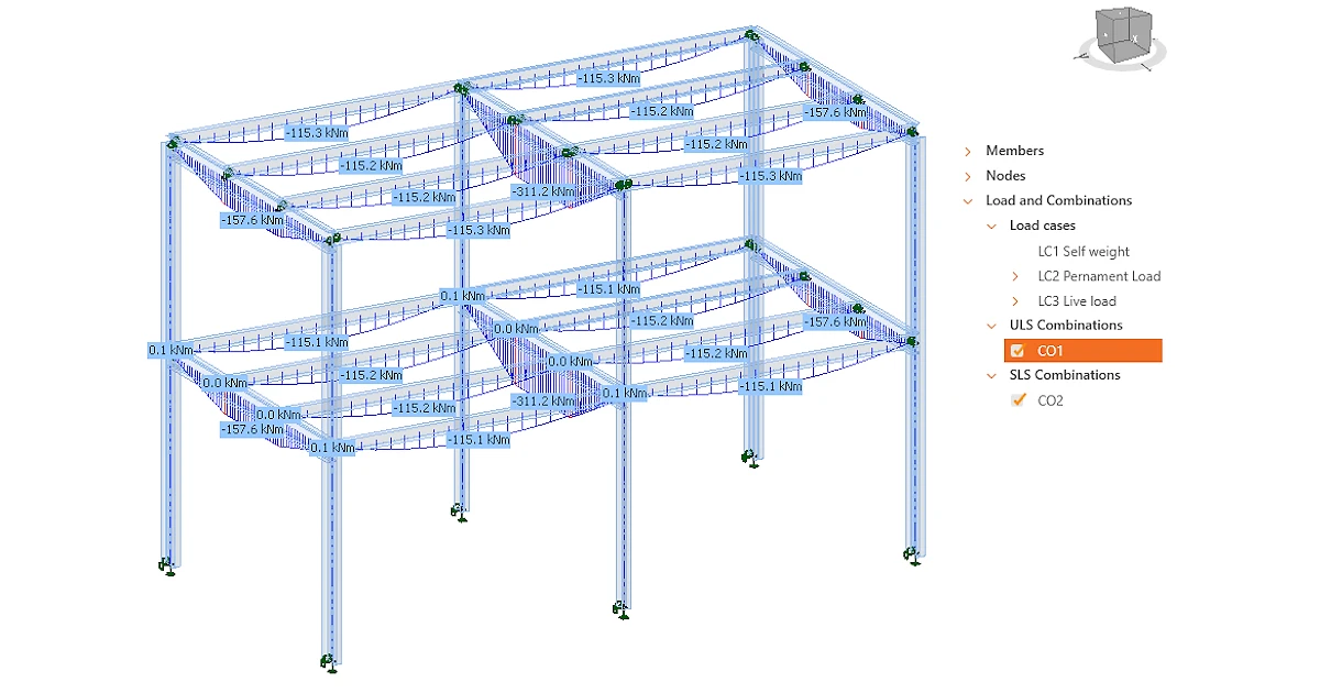
Linear analysis (LA) solves the whole Stability model using only 1D beam elements (6 DOF), assuming a linear elastic material and a first-order calculation (analysis on the original, undeformed geometry of the structure). No plates, bolts or welds are included in the linear analysis model.
Linear analysis is available on the MODEL tab. It gives a quick overview of how the structure carries the load before the more complex shell-element model is built and solved in the next step.
Typical uses of linear analysis are:
- checking that supports, member releases and loads are defined correctly (equilibrium, reactions, deformed shape);
- obtaining internal forces along all members.
Linear analysis does not check the resistance or stability of the members in the structure. Nevertheless, the calculated internal forces in the members (where available) are imported into the Connection application in the next step, connection design, for all defined load cases and load combinations.
2. Materially nonlinear analysis of the CBFEM part
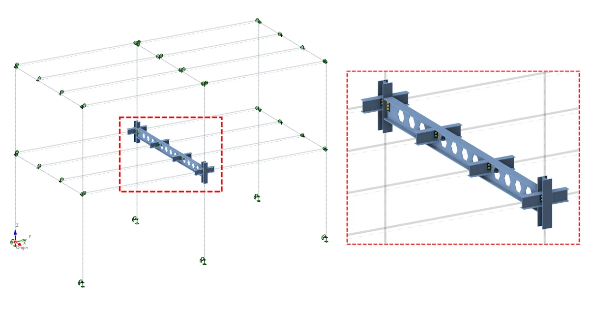
Materially nonlinear analysis (MNA) is associated with the DESIGN tab. On this tab, the user defines the part of the structural model to be analyzed in detail by selecting so-called CBFEM members. These CBFEM members, as well as the stubs of all adjacent 1D beam elements connected to them, are modeled with shell elements. Bolts, welds and anchors associated with the connections of these CBFEM members are represented by components.
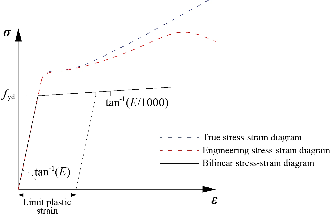
MNA uses an elastic-plastic material model and a first-order calculation (analysis of the original, undeformed geometry of the structure modeled using shell elements), which corresponds to the standard stress/strain analysis in IDEA StatiCa Connection.
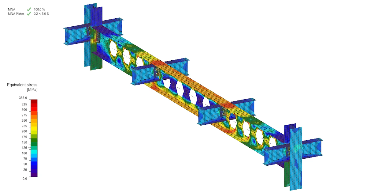
MNA checks the strength of the analyzed part without the effect of buckling. Plates are assessed by the maximum plastic strain, which is set to 5% by default.
The MNA model is also used for LBA and GMNIA. Therefore, a model that fails or does not converge in MNA should be fixed before the user continues to the next steps.
3. Linear buckling analysis
The structure is considered perfect without any geometrical or material imperfections, and the material is elastic in this analysis type. Linear buckling analysis (LBA) calculates the elastic critical load factors αcr and the corresponding buckling mode shapes (eigenmodes) of the CBFEM model.
The LBA results can be used to:
- identify the buckling mode: global sway buckling of whole structure, flexural, torsional, torsional-flexural or lateral-torsional buckling of the members, or local buckling of plates;
- decide whether GMNIA is needed, based on αcr (see below);
- select which mode shapes will be used for defining the global or member imperfections in GMNIA, and with what amplitude.
The need for GMNIA is decided from αcr, the factor by which the design loads would have to be increased to cause elastic instability.
A. Global (sway) buckling
For global (sway) buckling, EN 1993-1-1:2005, Cl. 5.2.1(3) allows first-order analysis when αcr ≥ 10 for elastic analysis and αcr ≥ 15 for plastic analysis. Because MNA is a first-order analysis with elastic-plastic material, the plastic limit applies:
| αcr from LBA | Meaning | Analyses required |
| ≥ 15 | second-order effects (analysis of the deformed structure) are negligible | MNA is sufficient |
| < 15 | second-order effects (analysis of the deformed structure) must be included | MNA and GMNIA |
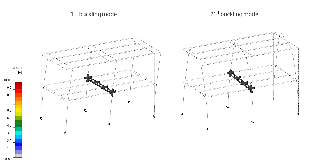
Example of global buckling modes
B. Member buckling
The limit αcr ≥ 15 comes from the rule in EN 1993-1-1 that decides whether the global analysis of a structure may ignore the effects of its deformed geometry. It was not written for buckling of individual members or local buckling of plates. LBA in IDEA StatiCa Stability finds all of these modes, so it is useful to understand how the limit relates to each of them.
A column or beam that buckles has no post-buckling reserve. Once it starts to deflect sideways or twist, the deformation grows and its resistance drops. Even small initial imperfections, such as a slight bow or residual stresses from rolling or welding, reduce the load a member can carry. This is why EN 1993-1-1 checks member buckling separately.
EN 1993-1-1 uses the non-dimensional (relative) slenderness to decide whether member buckling matters. It compares the plastic resistance of the cross-section with the elastic critical force of the member. A low value means the member is stocky: it would yield long before it could buckle elastically. EN 1993-1-1 allows buckling to be ignored only when the relative slenderness is no more than 0.2. For a fully utilized member, this corresponds to αcr of at least 25 for its buckling mode, which is stricter than the limit of 15 used to decide whether GMNIA is needed.
When LBA finds a member buckling mode with αcr between 15 and 25, MNA alone may slightly overestimate the resistance. This applies to flexural, torsional, torsional-flexural and lateral-torsional buckling. For a fully utilized member with αcr just at 15, the relative slenderness is about 0.26. Depending on the buckling curve assigned to the cross-section, the buckling curves of EN 1993-1-1 then reduce the resistance by about 1% to 5%. MNA does not include this reduction.
The difference is small, but it is not on the safe side. For member buckling modes with αcr below 25, it is therefore recommended to run GMNIA with imperfections applied in the shape of the relevant member buckling mode.
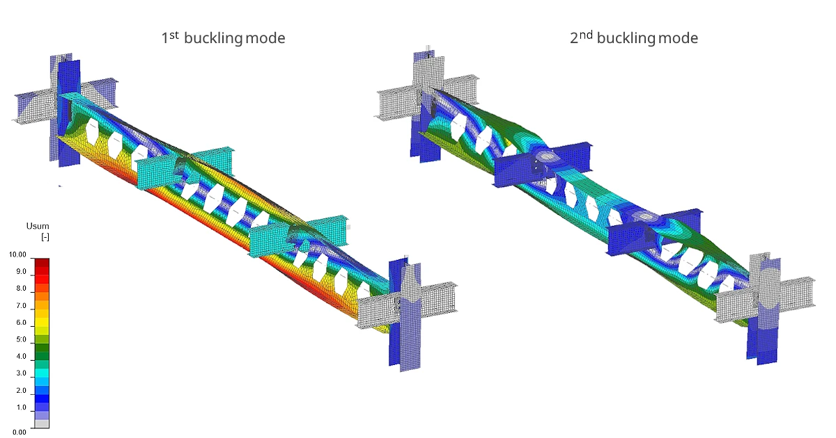
Example of member buckling modes
C. Local plate buckling
For local buckling of plates, the limit αcr ≥ 15 is very conservative, because plates behave differently from members after they buckle. When the middle of a plate supported along its edges starts to buckle, the stresses move towards the supported edges, which stay straight and can still carry load. The plate therefore keeps carrying load well beyond the moment it first buckles. This is called the post-buckling reserve.
EN 1993-1-5 takes this reserve into account. A plate supported on both longitudinal edges, such as a web or an internal part of a flange, loses no resistance until its elastic critical stress drops to roughly twice the yield strength. For a fully utilized plate, this means it keeps its full resistance as long as αcr of its local buckling mode is above about 2, which is far below the limit of 15. Local buckling concerns individual plates, such as stiffeners or a column web. How much load a buckled plate can redistribute depends on how many of its edges are supported. The limiting buckling factors below are based on design codes and research experiments, and include a margin for plates with free edges. The effects of local buckling can be neglected when αcr of the local buckling mode is at least:
- αcr ≥ 2 - in case of a 4-sided supported plate
- αcr ≥ 3 - in case of a 3-sided supported plate
- αcr ≥ 4 - in case of a 2-sided (neighboring) supported plate
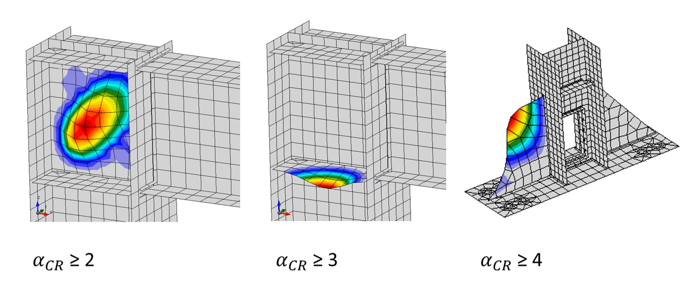
The exception is plates that behave like columns rather than plates. Examples are plates supported only on two opposite edges and short, wide panels whose buckled shape spans between the loaded edges. These have no post-buckling reserve, so they should be treated like member buckling, with the stricter limit applied.
- αcr ≥ 25 - in case of a 2-sided (opposite) supported plate or short, wide panels whose buckled shape spans between the loaded edges
In practice, when LBA in IDEA StatiCa Stability finds a local plate buckling mode, check how the buckled plate is supported and compare αcr with the corresponding limit. If αcr is above that limit, the MNA result gives (with exception for plates supported only on two opposite edges and short, wide panels whose buckled shape spans between the loaded edgesa) safe estimate of the plate resistance, even if αcr is below 15.
4. Geometrically and materially nonlinear analysis with imperfections
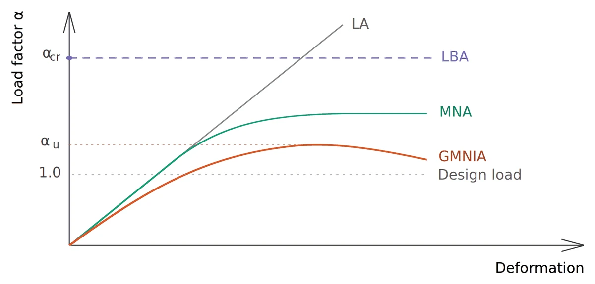
Geometrically and materially nonlinear analysis with imperfections (GMNIA) is the final and most complete check of the analyzed part of the structure. It uses the same CBFEM model as MNA, with elastic-plastic material. In addition, it calculates equilibrium on the deformed geometry and starts from a structure that is not perfectly straight and flat. Because it includes both yielding and the loss of stability, GMNIA gives the resistance of the analyzed part including buckling, without separate buckling checks.
Why imperfections are needed
A perfect structure in a nonlinear analysis often does not buckle at all, or buckles only at a load far above the real resistance. Real structures are never perfect. Members have a slight initial bow or twist, plates are not perfectly flat, rolling and welding leave residual stresses, and columns are erected slightly out of plumb. GMNIA represents all of these effects by equivalent geometric imperfections. The structure is modeled with a small initial deformation, so that it can lose stability in the same way as the real structure.
For more information about imperfections read article How to input the imperfections in Stability.
Evaluating the results
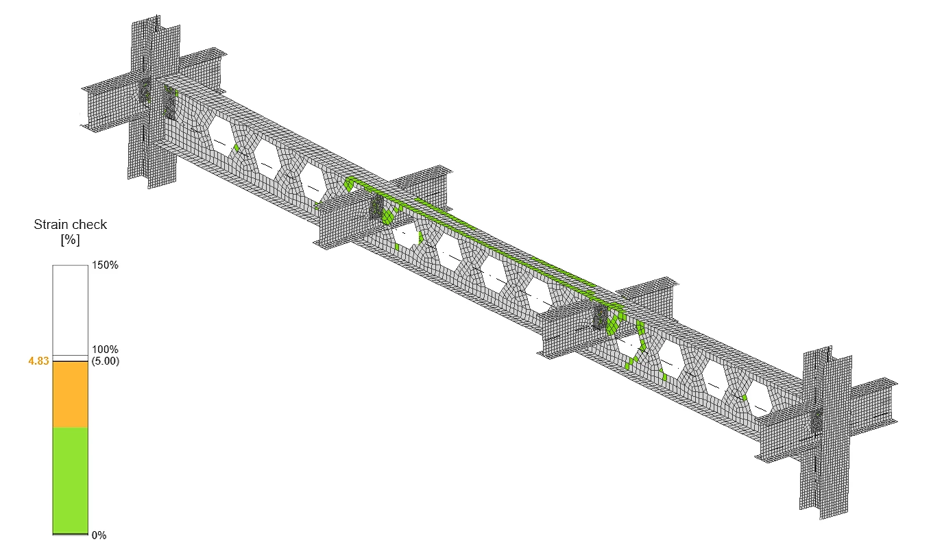
The GMNIA check passes when the structure carries 100 % of the design load and the plastic strain in the plates stays below 5 %. The ultimate limit state is reached either at the 5 % plastic strain limit or when the solver stops converging because the structure cannot take more load. In the second case the analysis ends below 100 % of the design load and the check fails.
Please note, that bolts, welds and anchors are currently not checked in GMNIA.