
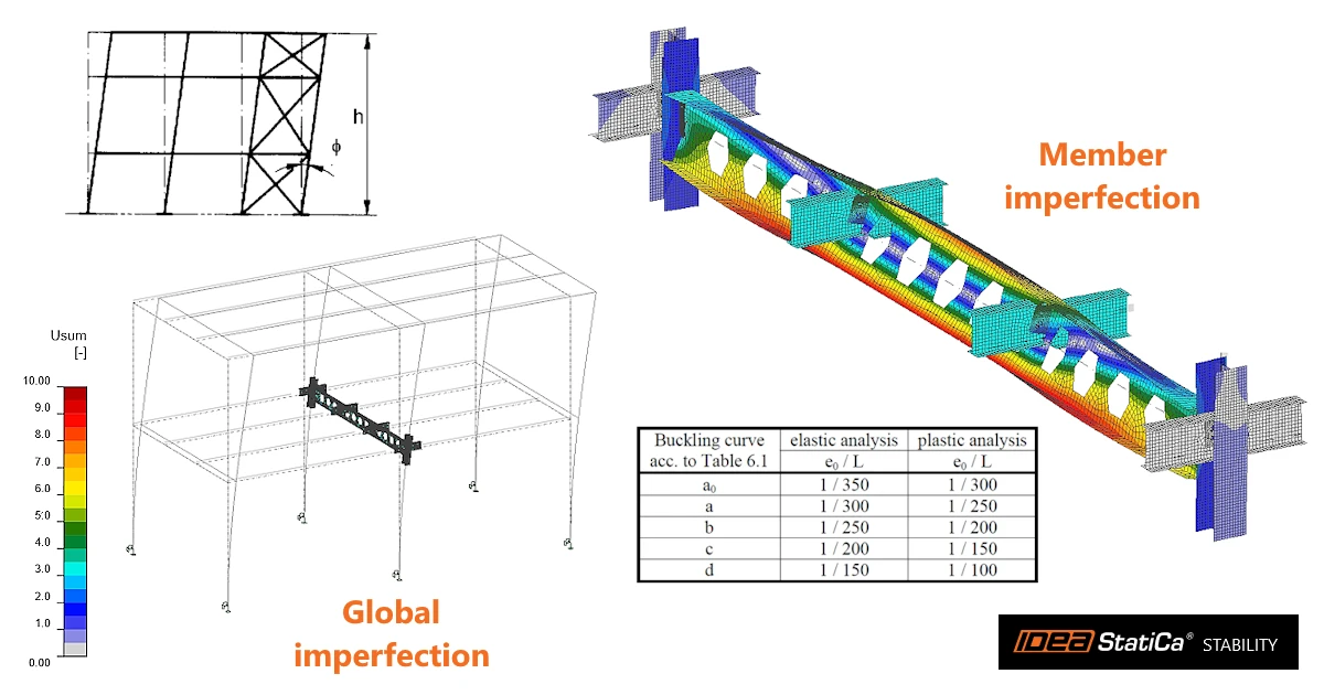


Stability defines global imperfections and member imperfections separately. Global imperfections are entered either as a simple inclination in X and Y or as a scaled buckling shape obtained from the LBA; member imperfections only as a scaled buckling shape obtained from the LBA with additional boundary conditions. Both are used in GMNIA.
The typical workflow is:
- Run MNA and LBA. The results of LBA are not needed if only the simple inclination is used.
- Review the buckling shapes and select those relevant for the imperfections.
- Determine the imperfection amplitudes according to the design code.
- Enter the imperfections on the property grid LBA+IMP tab on the CHECK tab.
- Run GMNIA considering both signs of the imperfections and take the most dangerous result as governing.
Types of imperfections and their definitions
In general, three types of imperfections should be applied in GMNIA.
A. Global (sway) imperfections of the structure
A global imperfection represents the fact that the structure as a whole is never perfectly vertical. Columns are erected slightly out of plumb and supports are not perfectly level, so the whole analyzed part starts slightly inclined. This imperfection matters mainly for structures sensitive to sway, where horizontal displacement of the whole structure increases the internal forces. It can be defined in two ways:
Definition of global imperfections - method "Simple inclination"
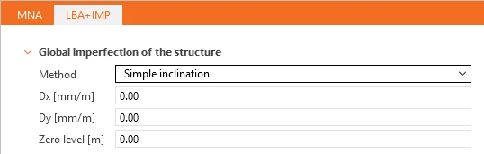
Simple inclination applies the global sway imperfection as an initial tilt of the whole structure, without any LBA results or buckling shapes. It is defined on the LBA+IMP tab in Global imperfection of the structure by the inclinations Dx and Dy in mm/m, i.e. the horizontal shift in the global X and Y directions per metre of height. Every node is shifted linearly with its height above the Zero level [m], typically set to the top of foundations or column bases, where the shift is zero.
Definition of global imperfections - method "Buckling shape"
Buckling shape applies the global imperfection as a scaled combination of buckling shapes obtained from the LBA, calculated with the boundary conditions defined on the MODEL tab. It is defined on the LBA+IMP tab in Global imperfection of the structure with Method set to Buckling shape and the Buckling shape imperfection amplitude [mm], i.e. the maximum deviation of the imperfect geometry.
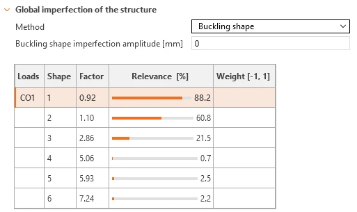
The table lists the shapes for each load combination with their:
- Factor is the critical load factor αcr by which the design load combination would have to be increased to cause elastic buckling of the structure in a given buckling shape.
- Relevance [%] is a measure of how easily the structure deforms in a given buckling shape. It compares the size of the deformed part of the structure with the elastic energy that the deformation needs. A shape in which a large part of the structure deforms with little energy gets a high relevance value, while a shape that deforms only a small part of the structure, or needs a lot of energy, gets a low value.
- Weight [-1, 1] is a factor that includes a buckling shape in the imperfection and sets its direction. Any non-zero value between −1 and 1 activates the shape, and the sign of the value determines the direction of the deformation. The weight multiplies the entered Buckling shape imperfection amplitude [mm], so the shape is applied with the amplitude weight × amplitude. An empty cell or zero means the shape is not used.
Select the shapes in which the whole structure sways, typically those with the lowest factor and high relevance, and run the GMNIA with considering both signs of the weights.
B. Member imperfections
A member imperfection represents the initial bow or twist of an individual member, together with the effect of residual stresses from rolling or welding. It is applied in the shape of the relevant member buckling mode from LBA (flexural, torsional, torsional-flexural or lateral-torsional). For structures sensitive to sway, member imperfections are combined with the global imperfection, not used instead of it.
Definition of member imperfections
Member imperfections are applied as a scaled combination of buckling shapes obtained from LBA with additional boundary conditions: supports in the X and Y directions are added at the ends of all related members connected to the CBFEM members, modeled by 1D beam elements. These supports prevent getting global buckling shapes, so the buckling shapes represent buckling of the individual members between their connection points. They are defined on the LBA+IMP tab in Member imperfection by the Buckling shape imperfection amplitude [mm].
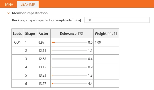
The table in Member imperfection works the same way as the one for global imperfections described above. The only difference is that the buckling shapes come from the LBA with additional boundary conditions. For each load combination (Loads), it lists the buckling shapes (Shape) with their critical load factor (Factor, αcr) and Relevance [%]. A Weight between −1 and 1 includes a shape in the imperfection and multiplies the Buckling shape imperfection amplitude [mm], and its sign sets the direction.
Select the shapes showing flexural, torsional, flexural-trosional or lateral-torsional buckling of the analyzed members and run GMNIA considering both signs of the weights.
C. Plate imperfections
A plate imperfection represents the initial out-of-flatness of individual plates, such as webs, flanges or stiffeners. It is applied in the shape of the relevant local buckling mode from LBA.
Definition of plate imperfections
Plate imperfections are defined in the same table for Member imperfection; there is no separate input for them. If the table contains buckling shapes representing local plate buckling of flanges or webs, include them in the imperfection by setting a non-zero Weight for those shapes.
Displaying imperfections
The Imperfection group on the CHECK tab offers three ways to display the imperfections in the 3D scene:

- LB shape displays the buckling shape from the table and row that currently have the focus.
- Partial displays the imperfection of the type whose table currently has the focus: global or member.
- Total displays the sum of all imperfections, regardless of the focus. This is the imperfect geometry that enters GMNIA.
Amplitudes of imperfections based on the design codes
There are guidelines for each code on how to determine imperfections, which you input in Stability for the GMNIA analysis. Below are the definitions described in Eurocode.
Global (sway) imperfections
Global imperfections of the structure are described in EN 1993-1-1, Cl. 5.3.2 (3). The structure should be inclined in the form of equivalent sway imperfection according to the following figure.
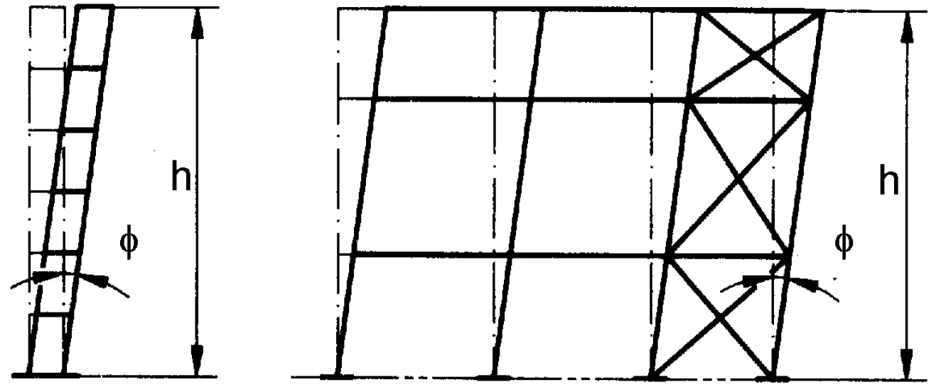
Equivalent sway imperfection (from EN 1993-1-1 – Figure 5.2)
The angle of imperfection is:
where:
- ϕ0 = 1/200 – basic value of imperfection
- – reduction factor for height h applicable to columns
- h – height of the structure in meters
- – reduction factor for the number of columns in a row
- m – number of columns in a row, including only those columns which carry a vertical load NEd not less than 50 % of the average value of the column in the vertical plane considered
Member imperfections
Local imperfections of members are described in EN 1993-1-1, Cl. 5.3.2 (3). The imperfection amplitude e0 is calculated in Table 5.1, where the plastic analysis should be used.
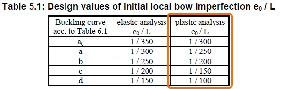
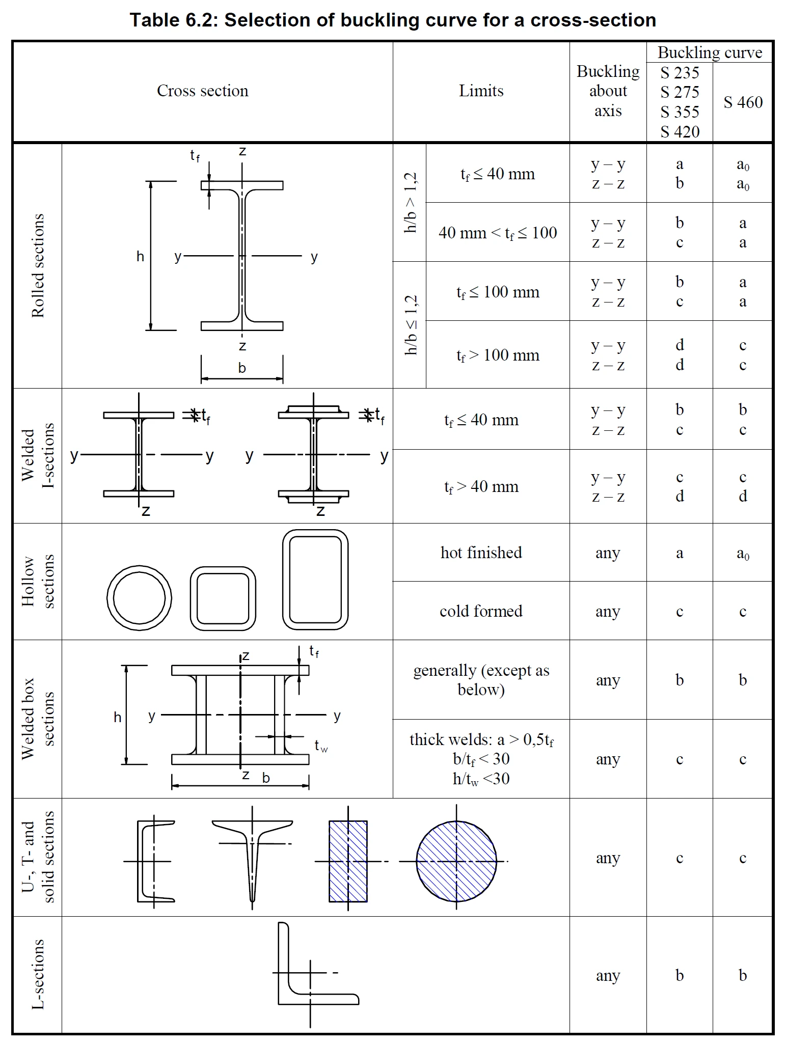
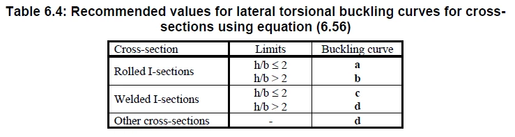
To determine the buckling curve in the tab, you need to decide, based on the displayed buckling shape in LBA analysis in Member, whether:
- Member is predominantly compressed where flexural, torsional, or torsional-flexural buckling is expected, and use Table 6.2,
- Or if the member is predominantly bent and the main failure mode is lateral-torsional buckling, and use Table 6.4.
Local plate imperfections
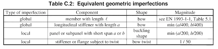
The amplitudes follow EN 1993-1-5, Cl. C.5. For slender plates, the local imperfection is 1/200 of the shorter span of the plate panel. For slender (class 4) cross-sections, combine at least two buckling modes, so that local and member buckling can interact.
Direction of imperfections
Each imperfection should be applied in both the positive and the negative direction, and the more unfavourable result is decisive. When several imperfections are combined, all combinations of their directions should be calculated.