
ETABS BIM link for reinforced concrete wall design (EN)
As a pre-requisite for this link, Microsoft .Net 6 is required. This can be downloaded here. This should also be installed with administrator rights.
How to activate the link
- Download and install the latest version of IDEA StatiCa
- Make sure that you are using a supported version of your FEA solution
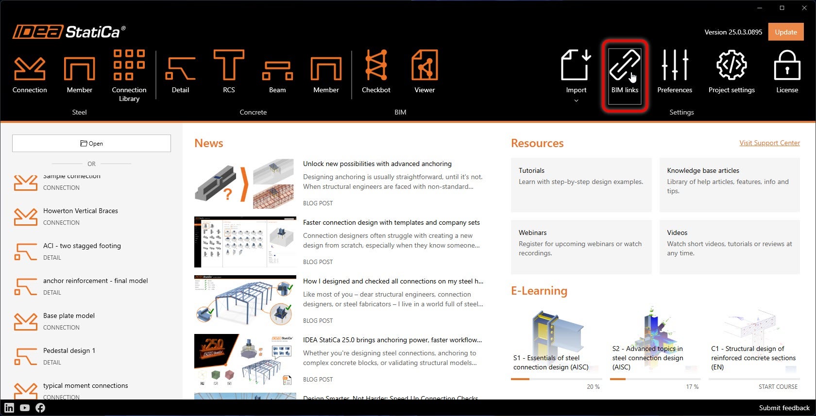
IDEA StatiCa integrates BIM links into your FEA software during its installation. You can check the status and eventually integrate more BIM links by running IDEA StatiCa and opening the BIM links. Please note that some FEA software require additional steps to fully activate their BIM link to IDEA StatiCa.
A notification "Do you want to allow this app to make changes to your device?" may appear, if so, please confirm with the Yes button.
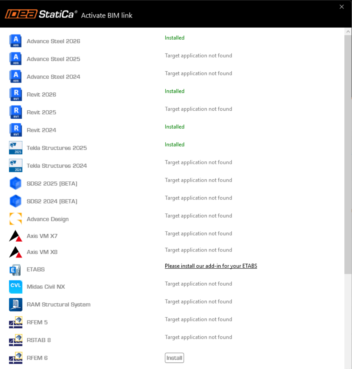
By clicking Install, the BIM link for the selected software is integrated. The screen also tells you the status of other BIM links.
There are some additional manual steps required in ETABS to finish the integration procedure:
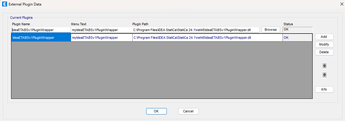
Start ETABS and Click Tools > Add/Show Plugins to open the Plugin Manager dialog. This option lets you install and add add-ins (programs) to the appropriate places in the ETABS menu.
Browse for
C:\Program Files\IDEA StatiCa\StatiCa 25.1\net48\IdeaETABSv1PluginWrapper.dll
(for older versions of IDEA Statica C:\Program Files\IDEA StatiCa\StatiCa 23.0\IdeaETABSv1PluginWrapper.dll
or C:\Program Files\IDEA StatiCa\StatiCa 22.1\ETABSv18PlugIn_IDEAStatiCa.dll).
You can edit the plugin's name displayed in your dropdown menu as IDEA StatiCa Checkbot, then click Add.
Remarks
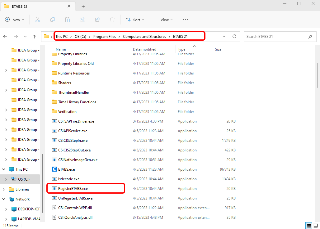
If the window with the IDEA StatiCa Checkbot doesn't appear, please go to C:\Program Files\Computers and Structures\ETABS 22 and run as Administrator the file RegisterETABS.exe.
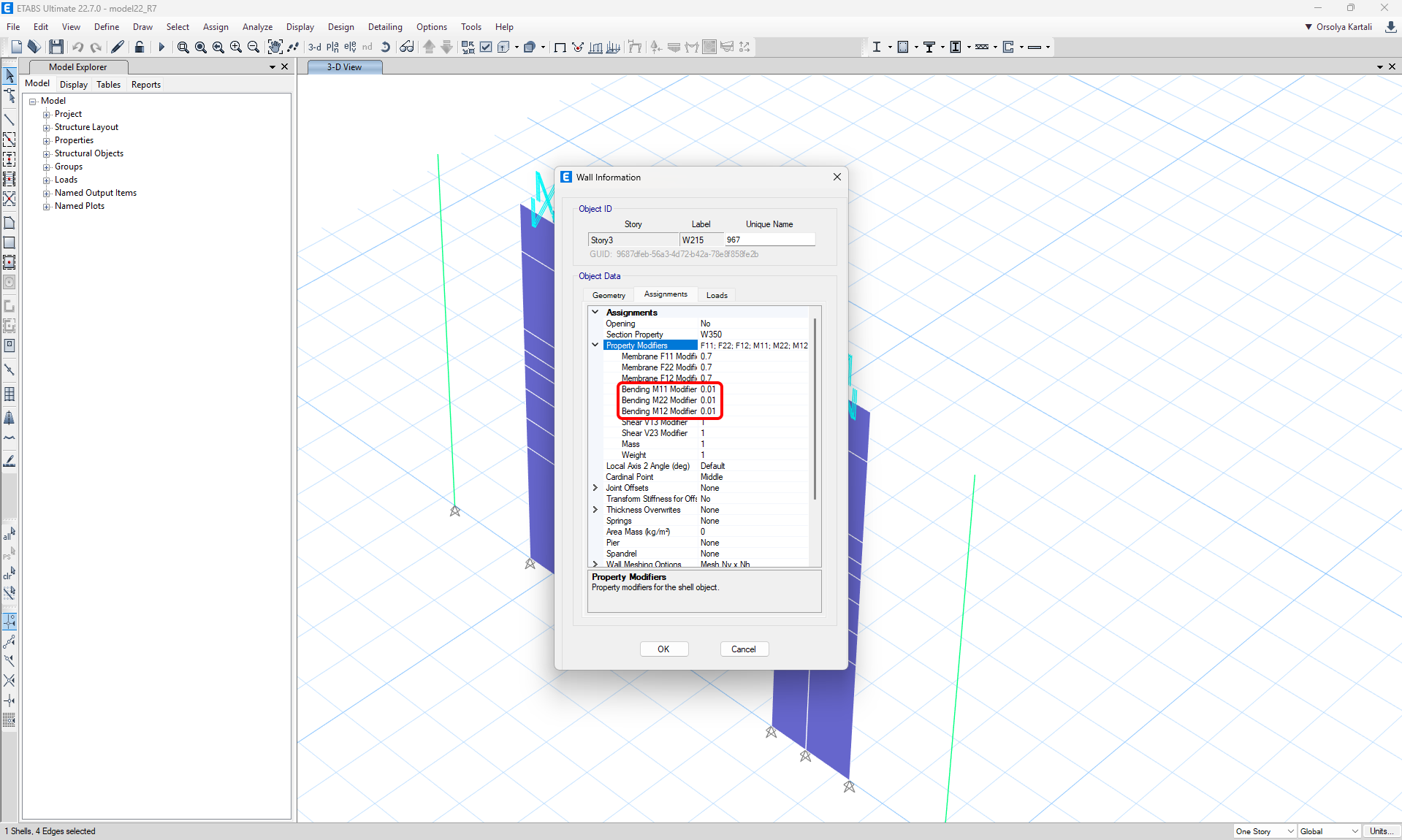
Detail calculates only with in-plane loads. To ensure that the wall transfers mainly in-plane loading, we can reduce the out-of-plane stiffness of the wall in ETABS. This will secure realistic load redistribution and Detail receives in-plane forces.
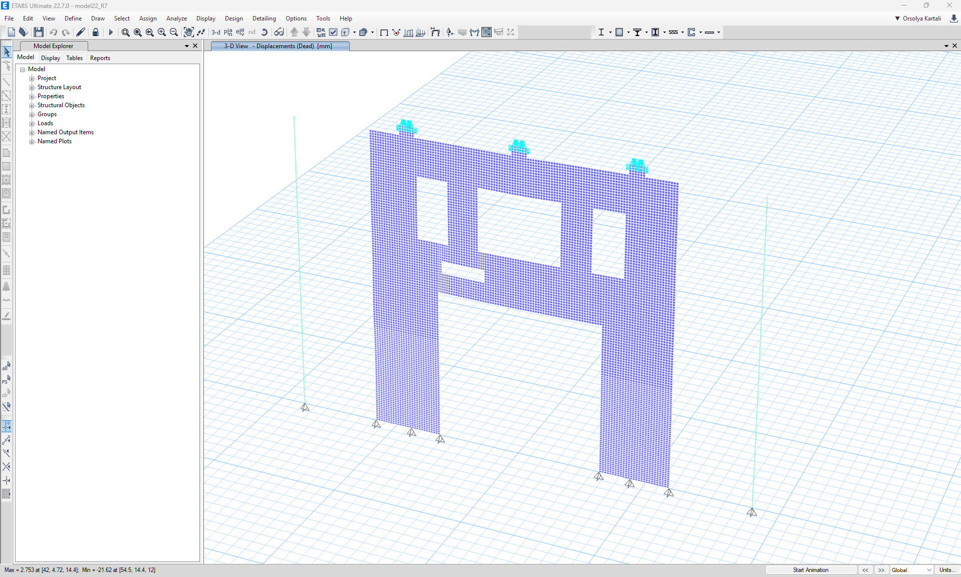
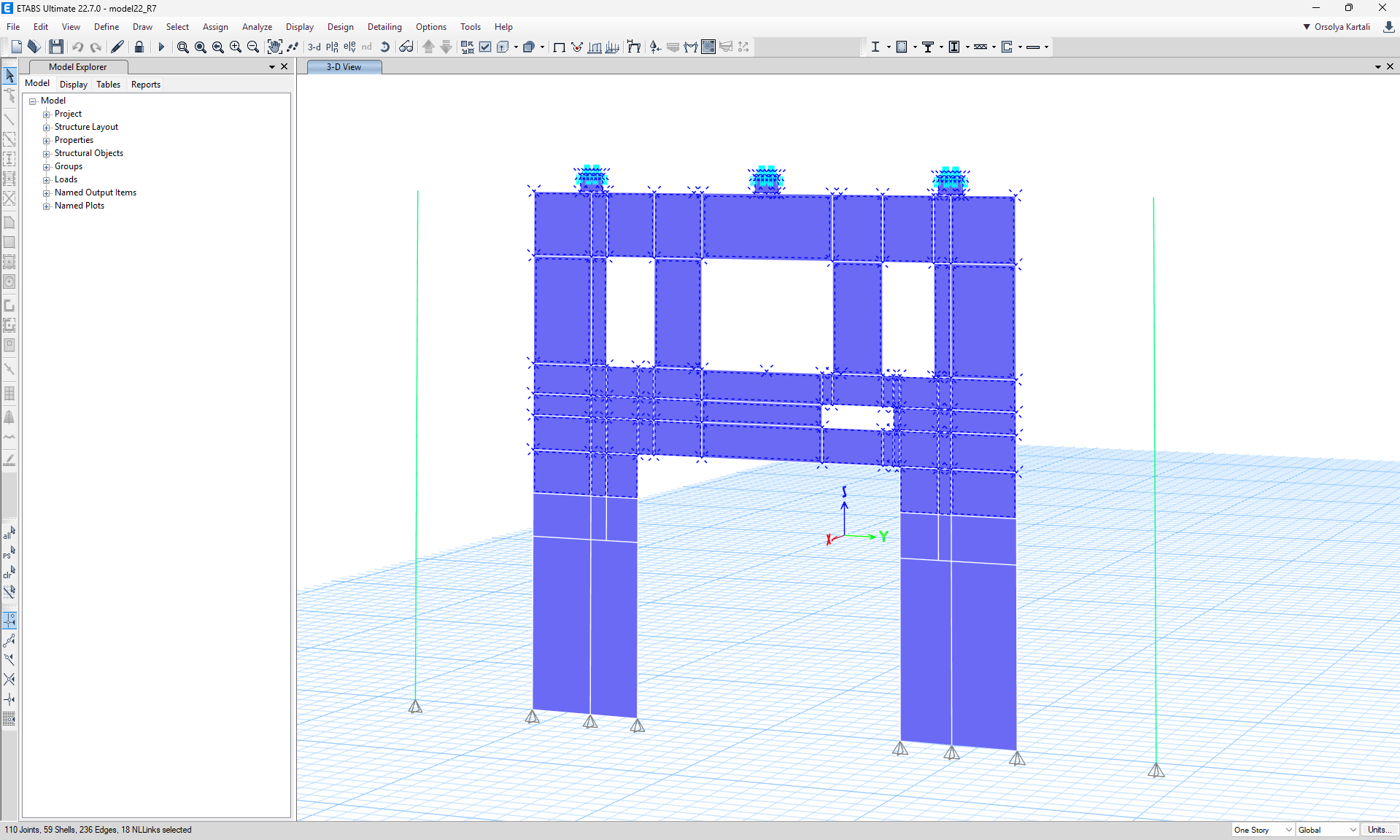
Meshing of the exported wall in ETABS should be set as 100 mm x 100 mm or smaller to make sure the mesh is fine enough for accurate force transfer and analysis.
Also, when a frame is connected to the analyzed wall, you need to use rigid link (light blue color in the picture above) to ensure proper distribution of internal forces from frame to shell – not concentrated into one node only.
How to use the link
Open the attached EN project in ETABS and run the calculation.
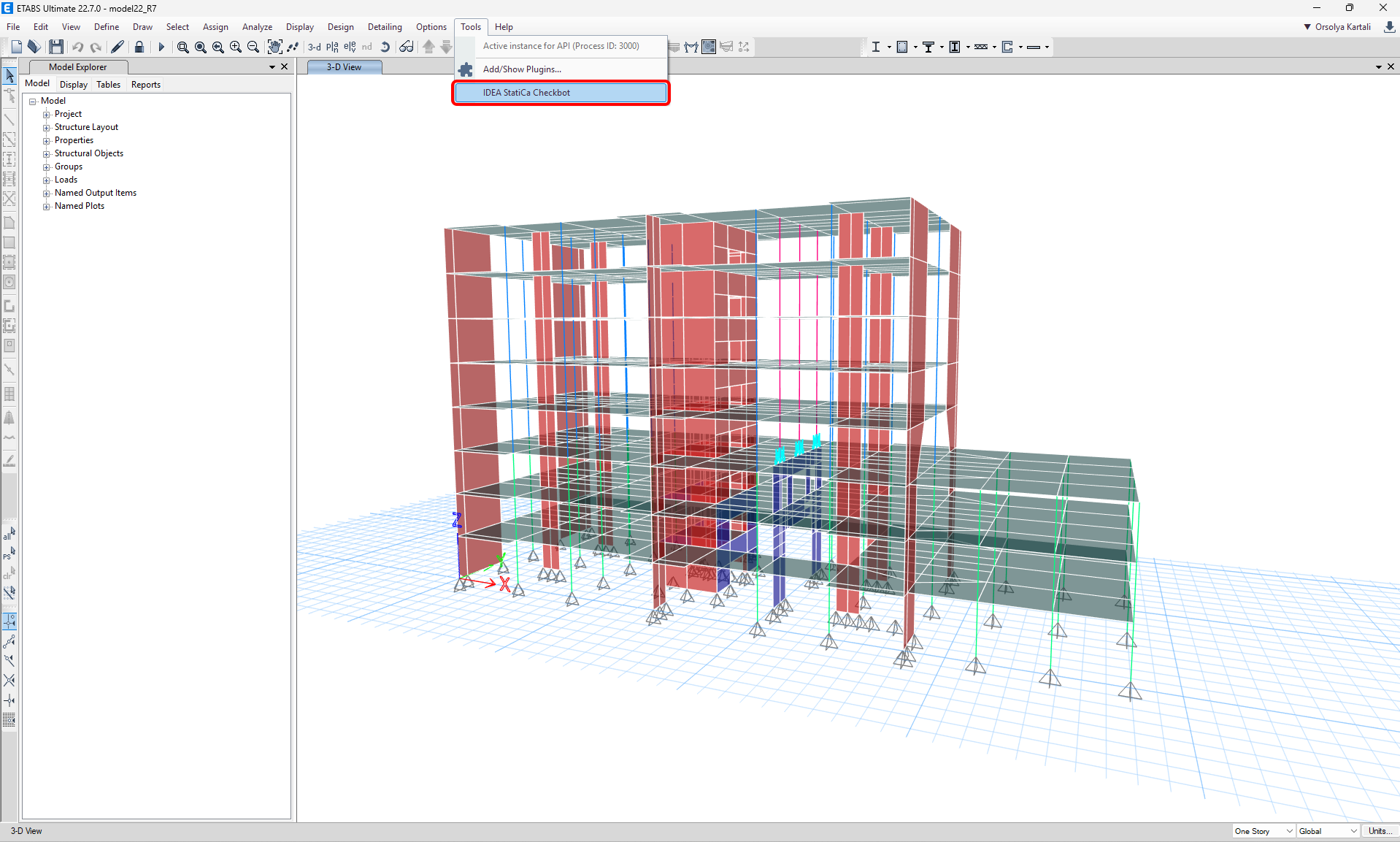
The BIM link should be automatically integrated. You can find it in the top ribbon under Tools -> IDEA StatiCa Checkbot. This will open the Checkbot application.
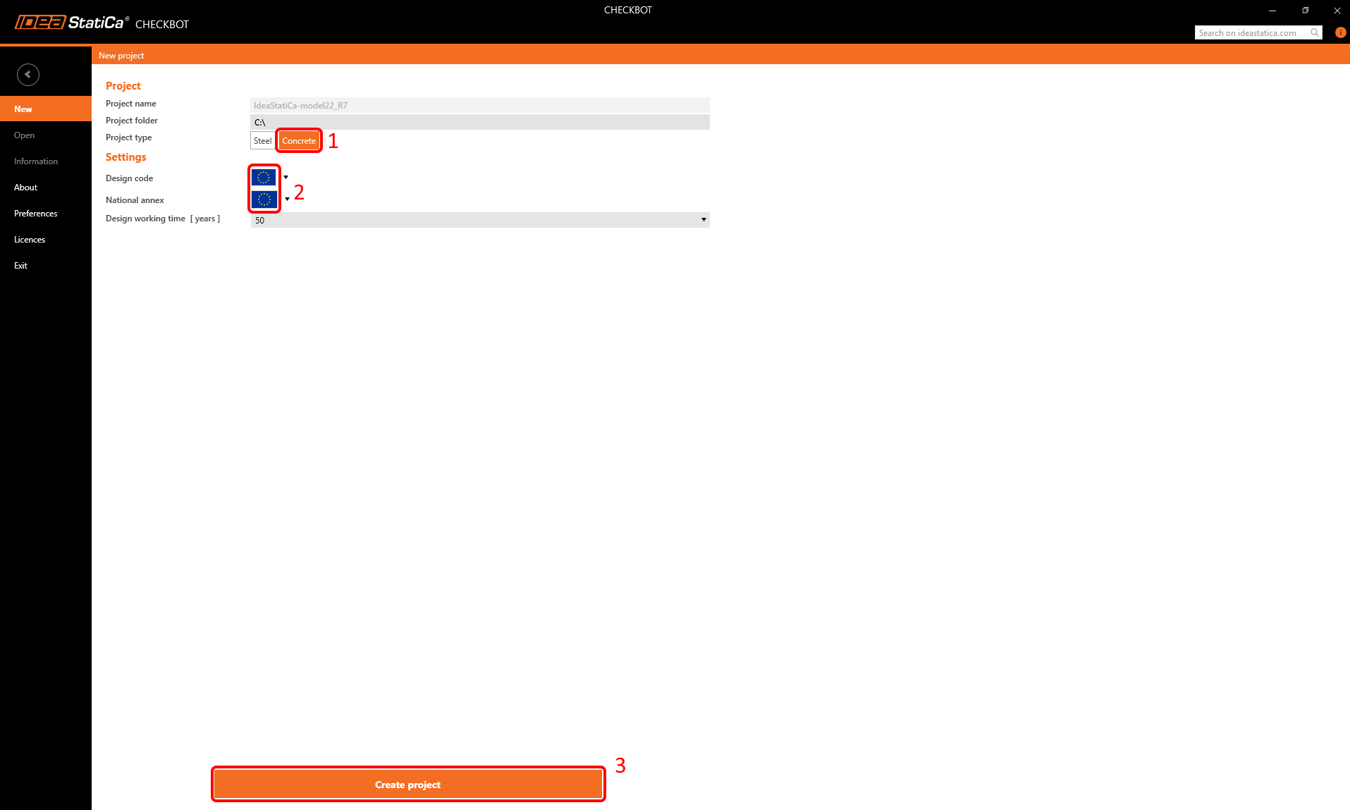
Once in the window of Checkbot, choose a Concrete project, and the design code you want to use – Eurocode in our case. Then click Create project.
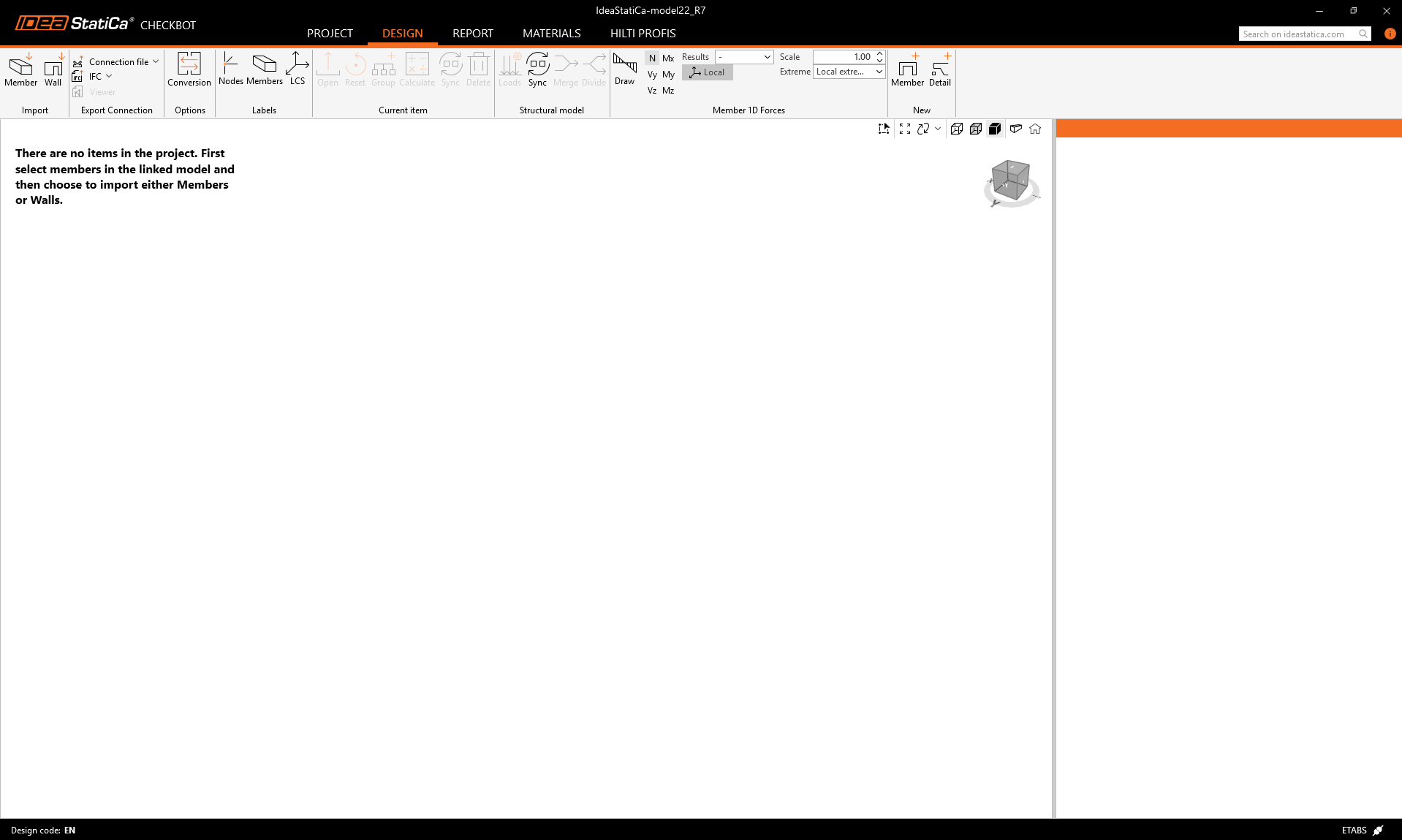
This will open an empty Checkbot project, where you can import structural elements from your ETABS projects.
Going back to ETABS, we will display only the selected transfer wall, which will be used for the import.
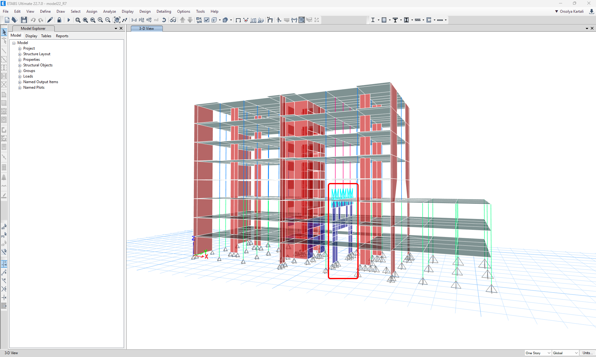
Select the upper part of the transfer wall using area selection.
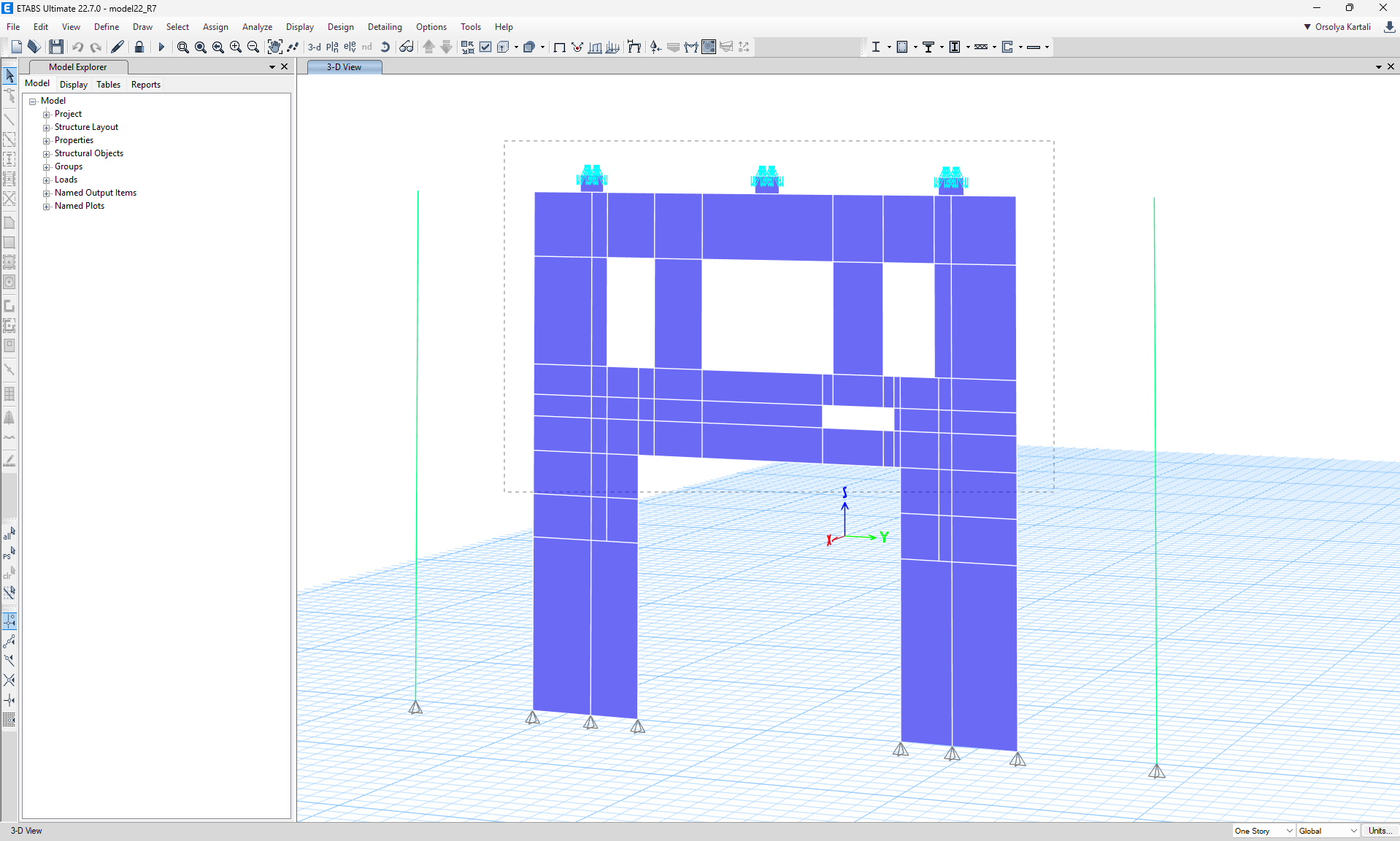
See the selected wall parts below:
Import
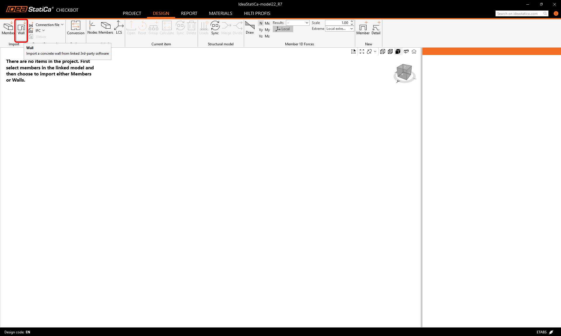
Return to the Checkbot window, and click the Wall button. This will import all selected wall elements from the ETABS project.
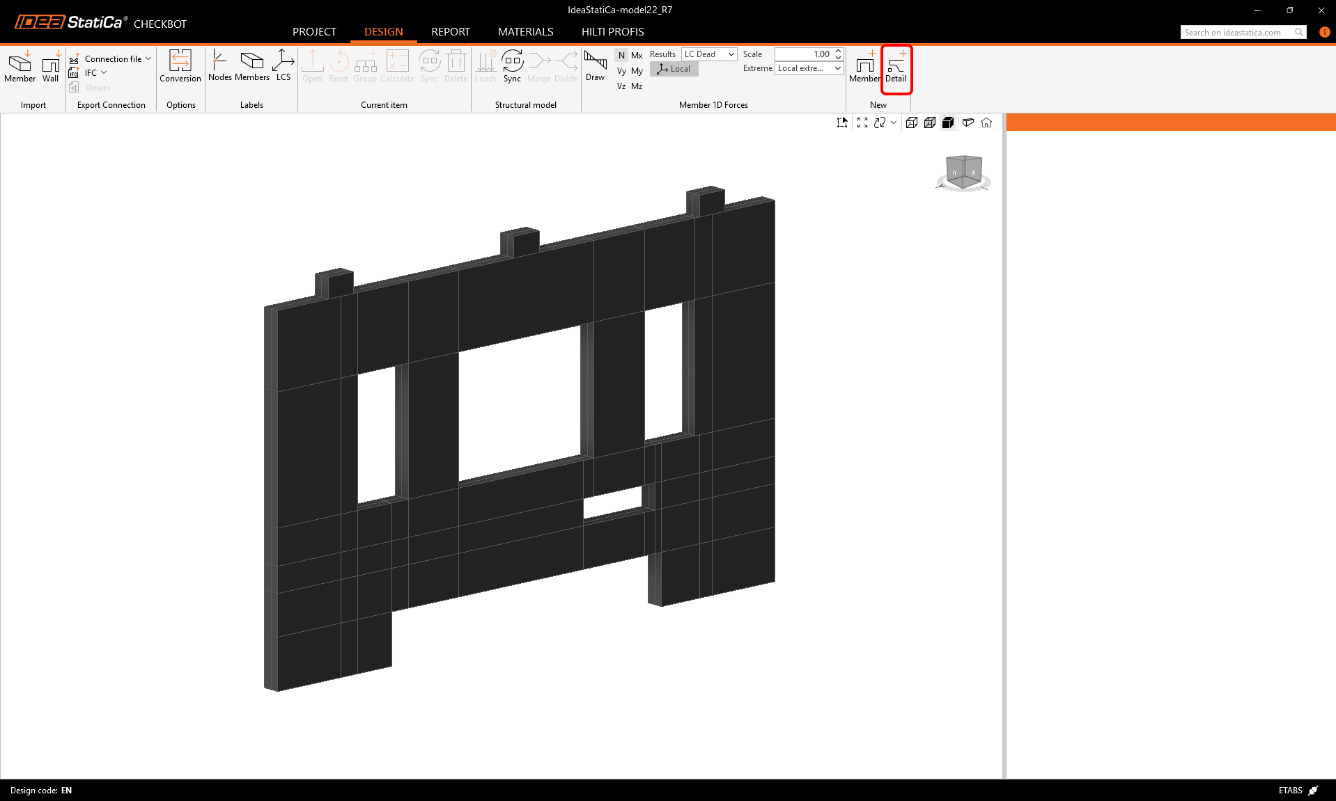
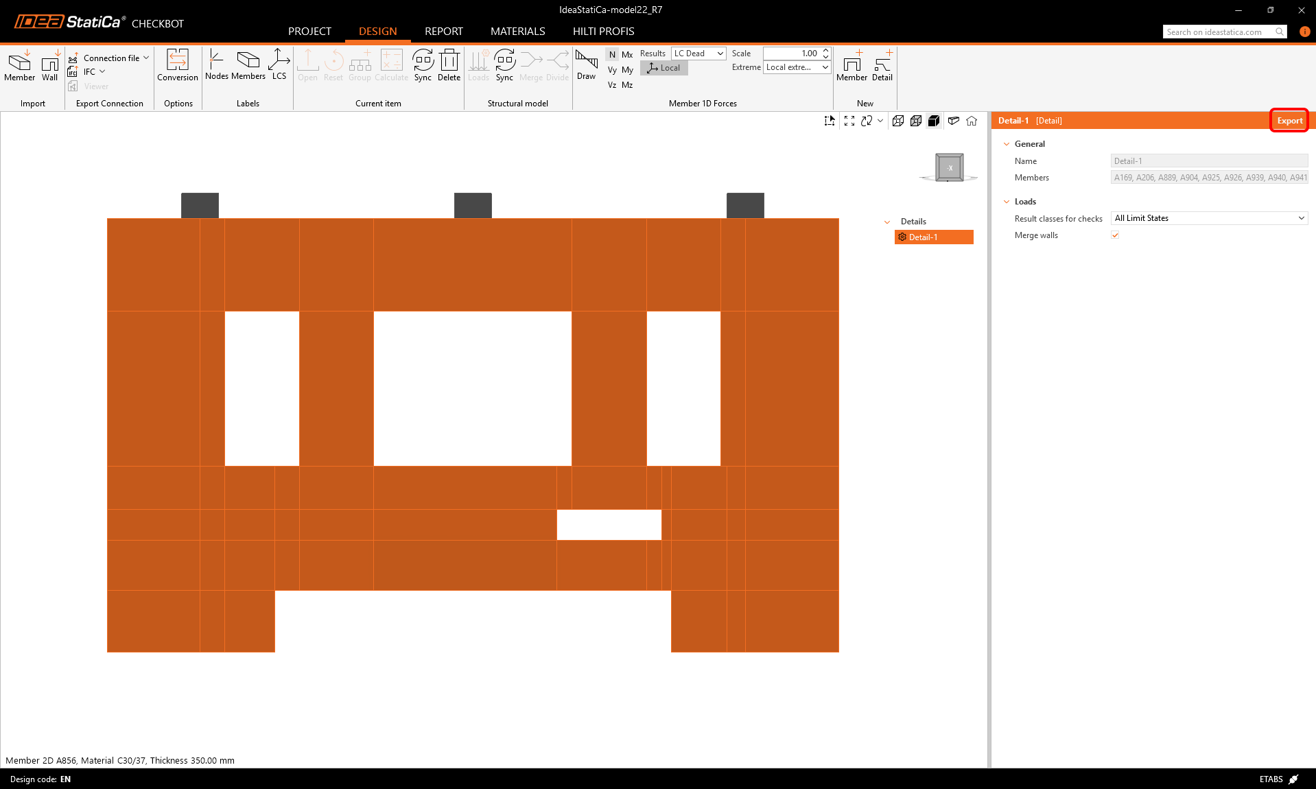
After import, we should see the wall in Checkbot. We will now export it into the Detail application by first clicking the Detail+ button in the top ribbon:
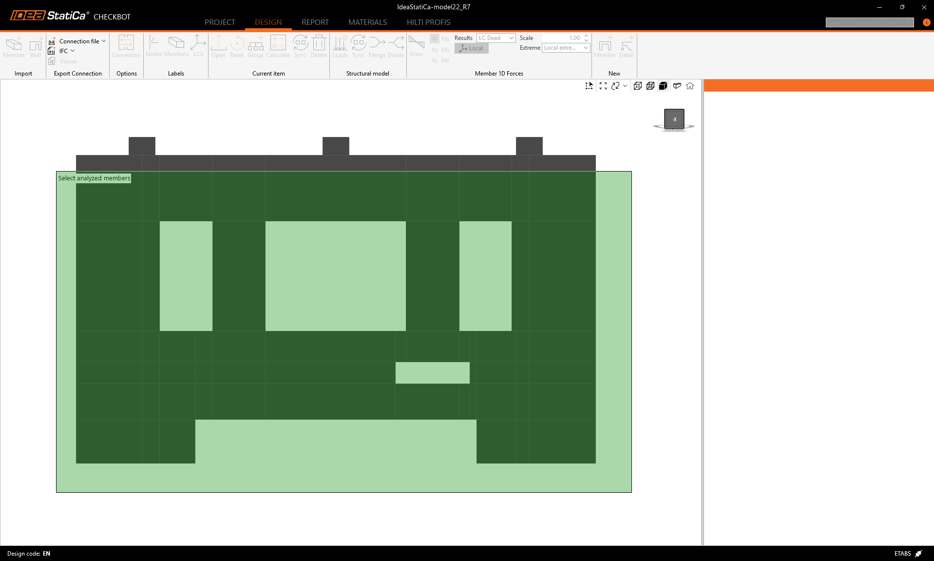
We can select the wall using area selection.
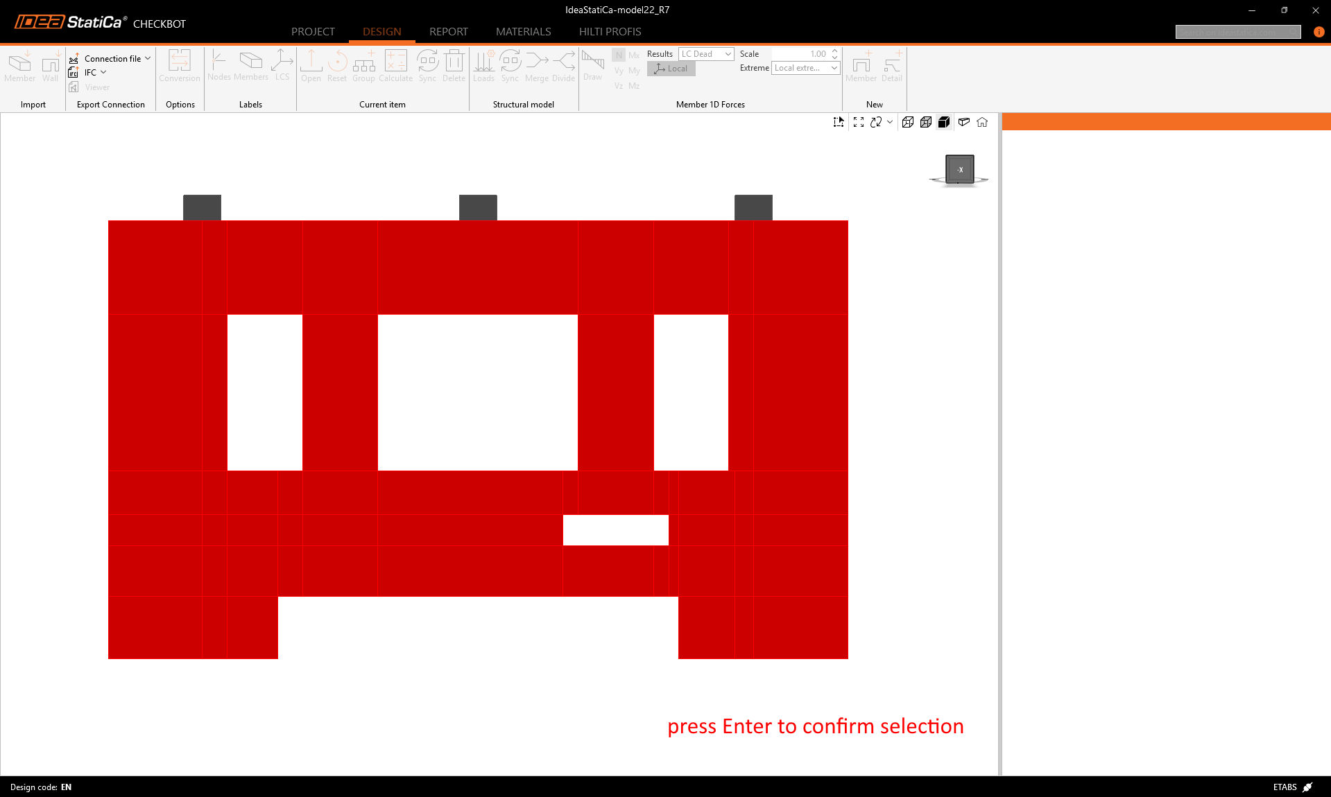
The selected parts are highlighted in red. We can confirm the selection with the Enter button.
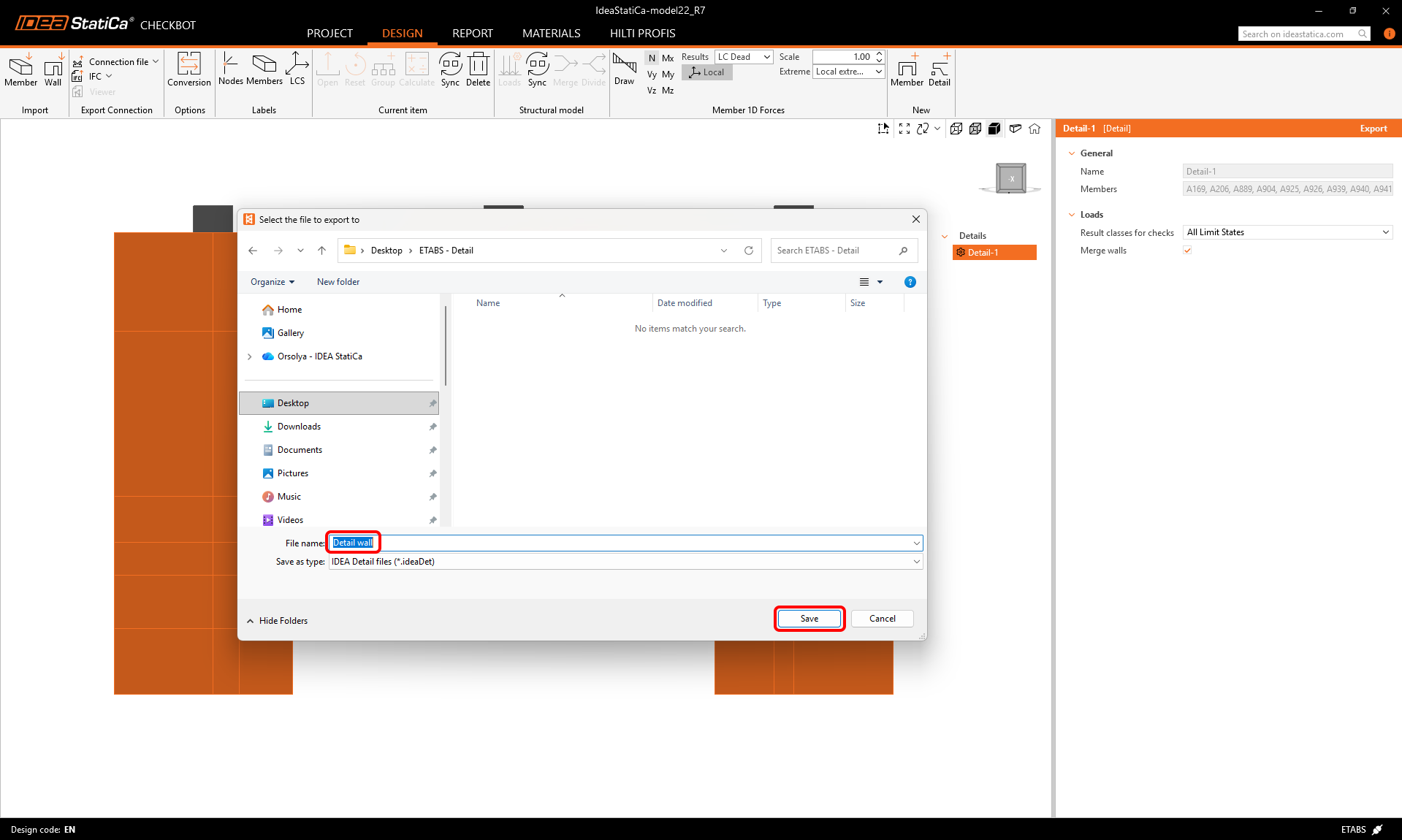
By clicking the Export button, a Detail project is created. All walls with the same thickness will be merged into one.
We can save the Detail project now.
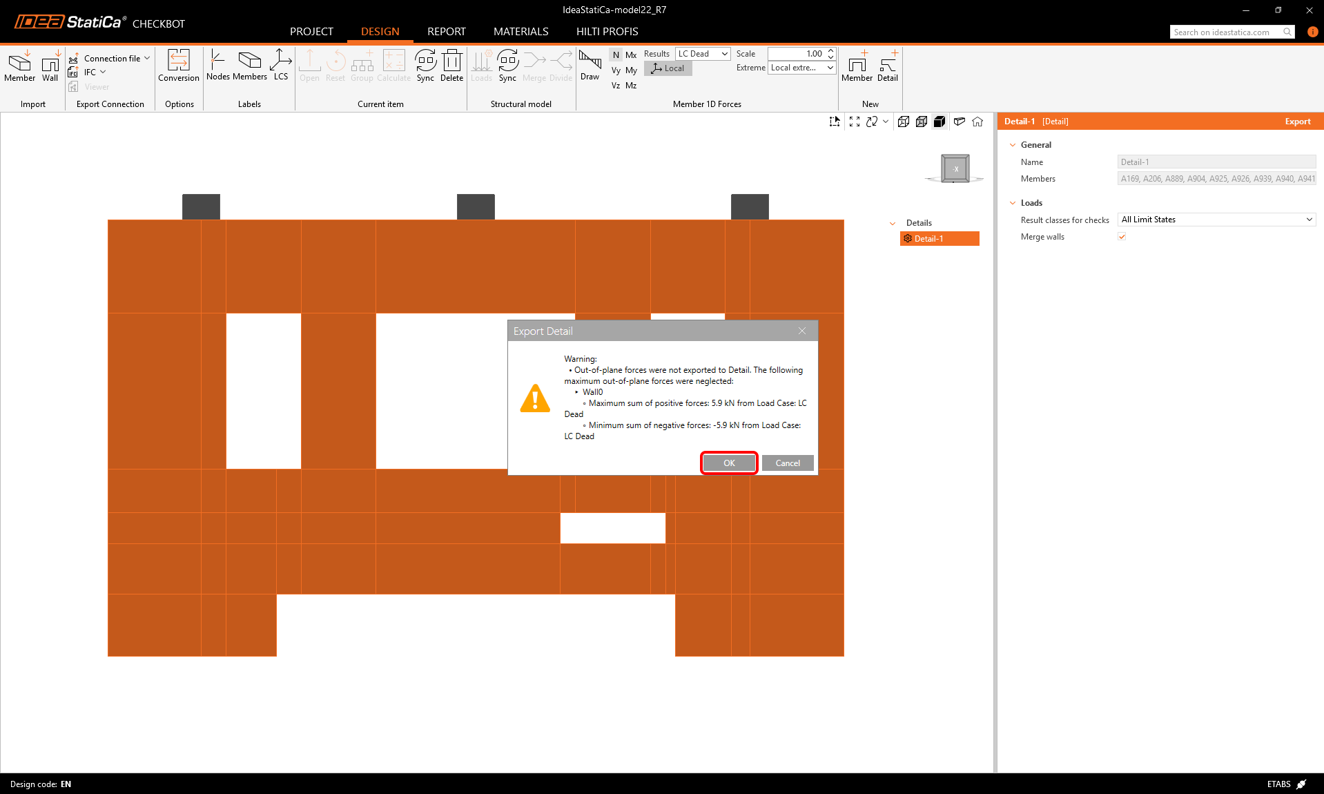
During the export, the following warning message can appear. Be aware that IDEA StatiCa Detail 2D works with a vertical wall model and only calculates with in-plane loading. Any out-of-plane effects coming from ETABS will be neglected. The warning message contains the values of the neglected out-of-plane loads and the corresponding load cases as well.
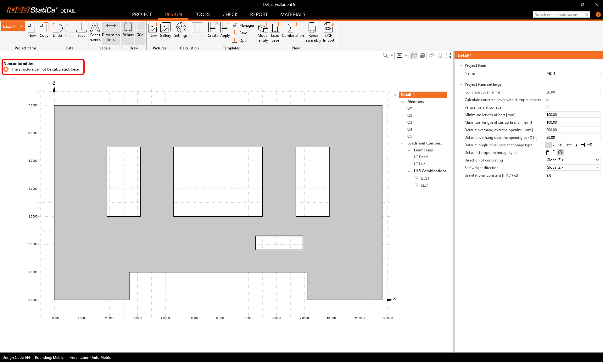
Model
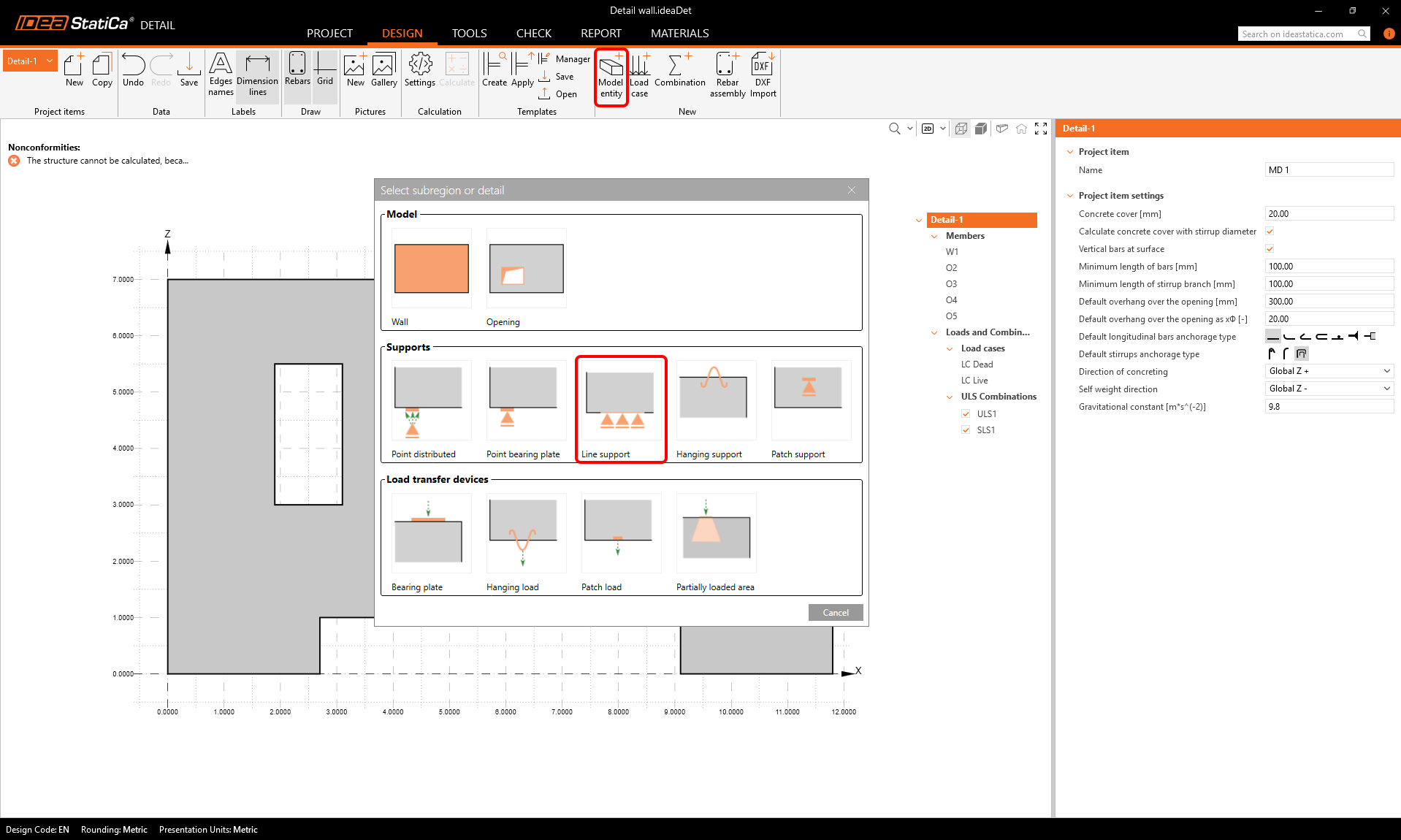
The exported Detail project opens automatically. We can see the following nonconformity message that says that the structure cannot be calculated because is has no supports. Also, we do not have any reinforcement in the wall yet.
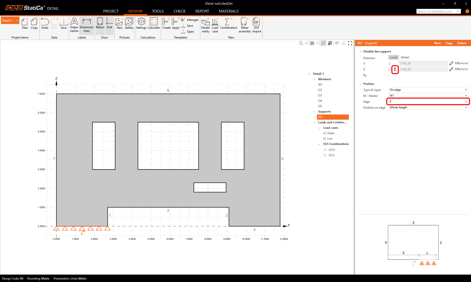
Let's add the supports first. Those need to be defined in correspondence with the global model. Click Model entity in the top ribbon, and select Line support.
Assign the support edge 8 and deactivate the "compression only" functionality (that is turned on by default).
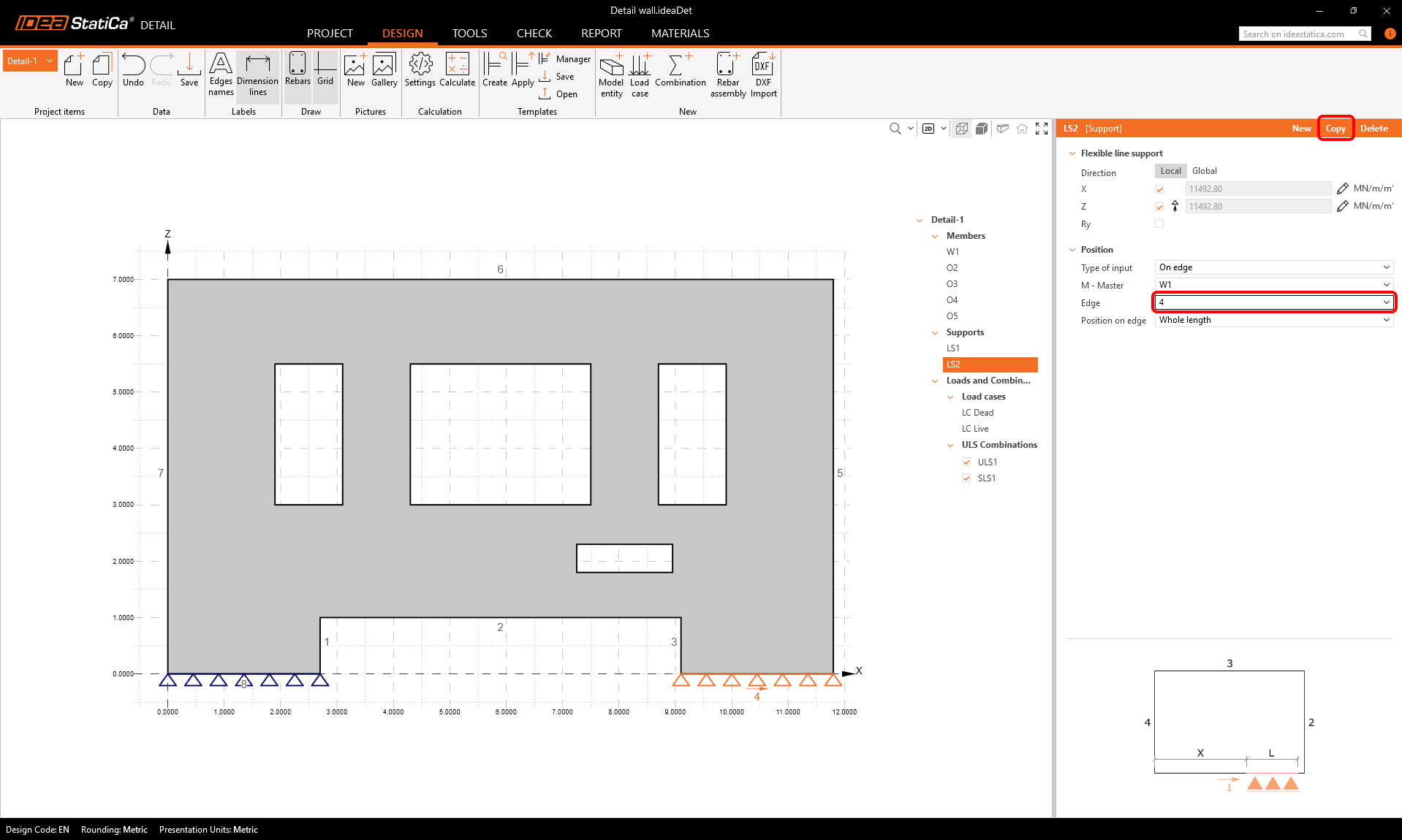
We can copy the first support to create the second one, assigned to edge 4.
Loads
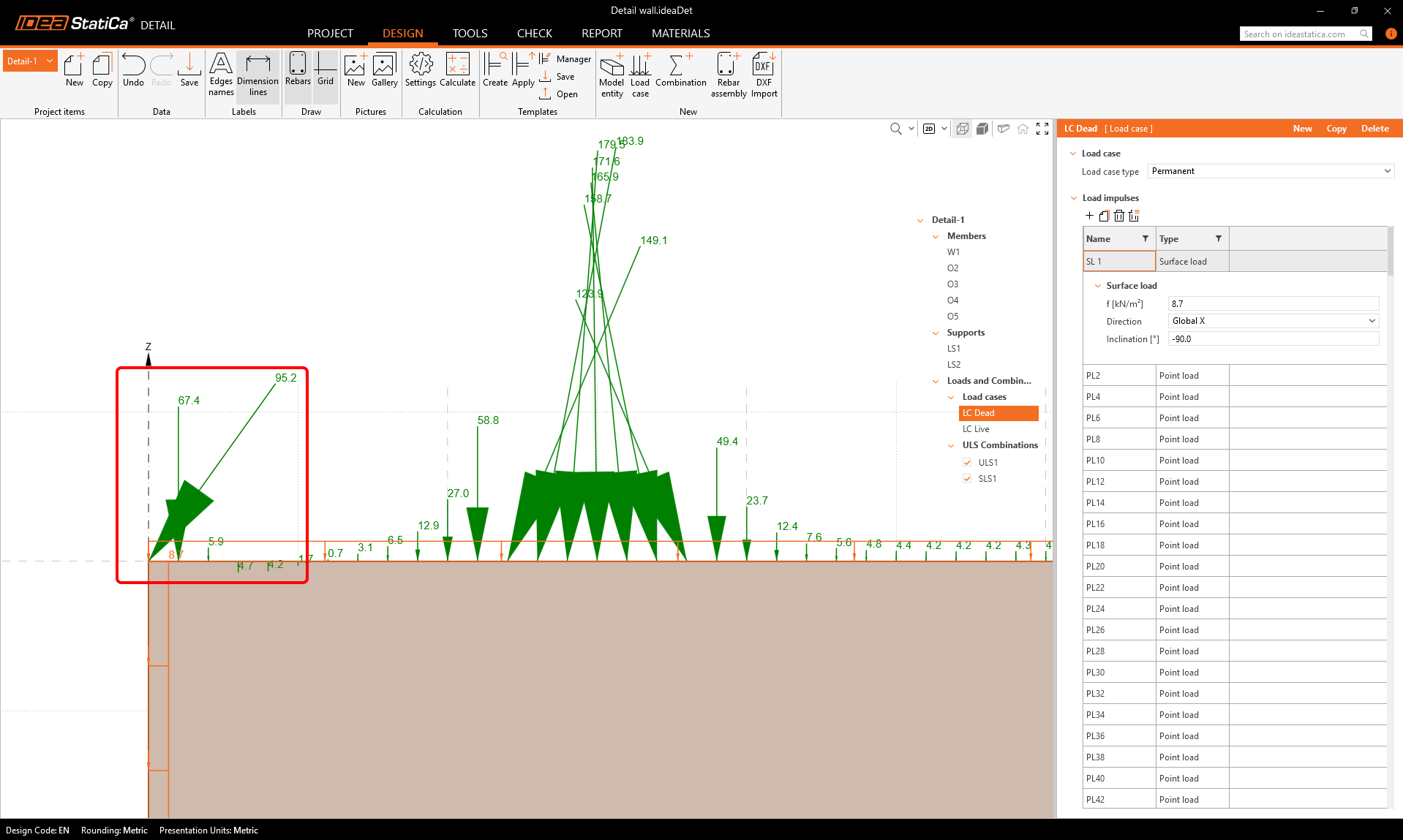
As can be seen, two load cases were imported from ETABS, one is permanent, the other is variable. The process of the force import is described in detail in this article.
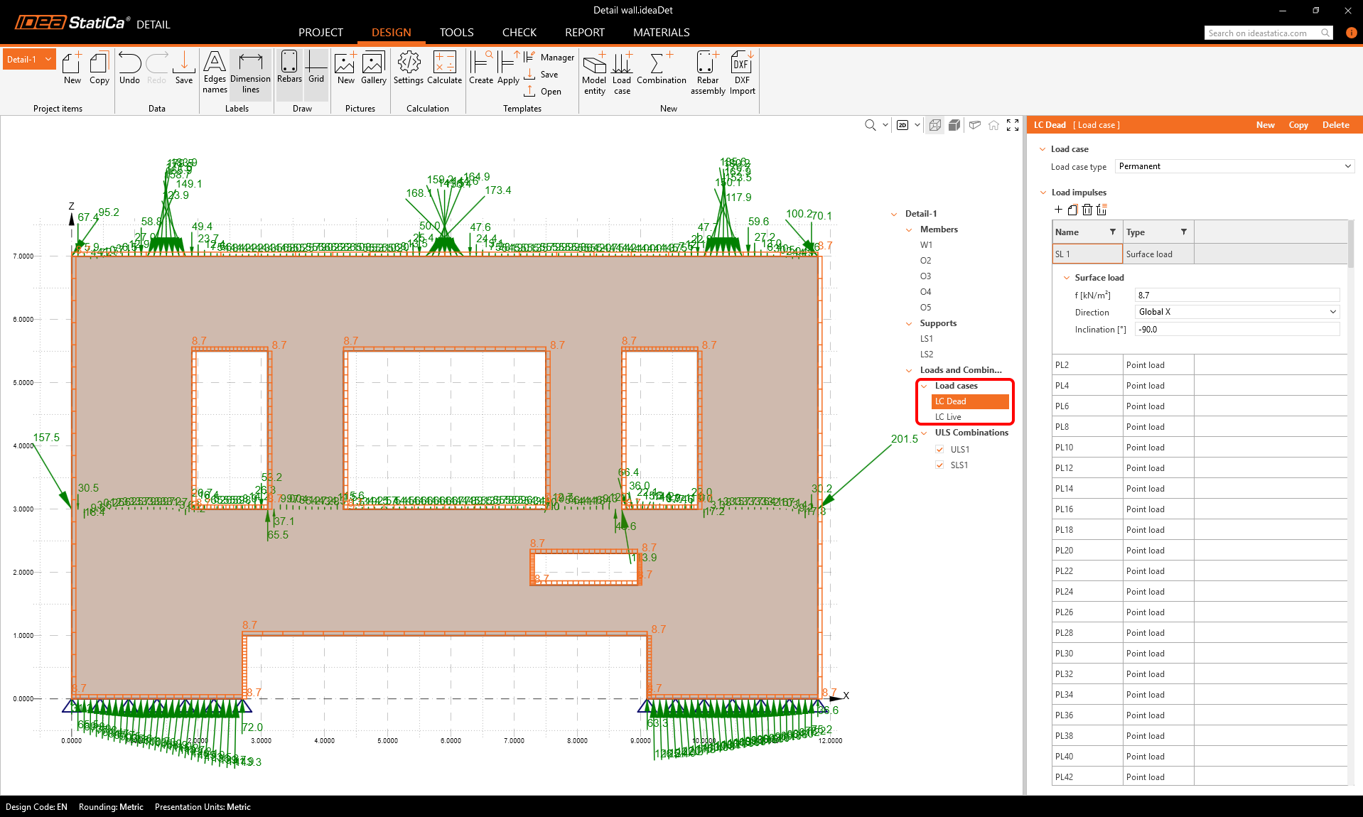
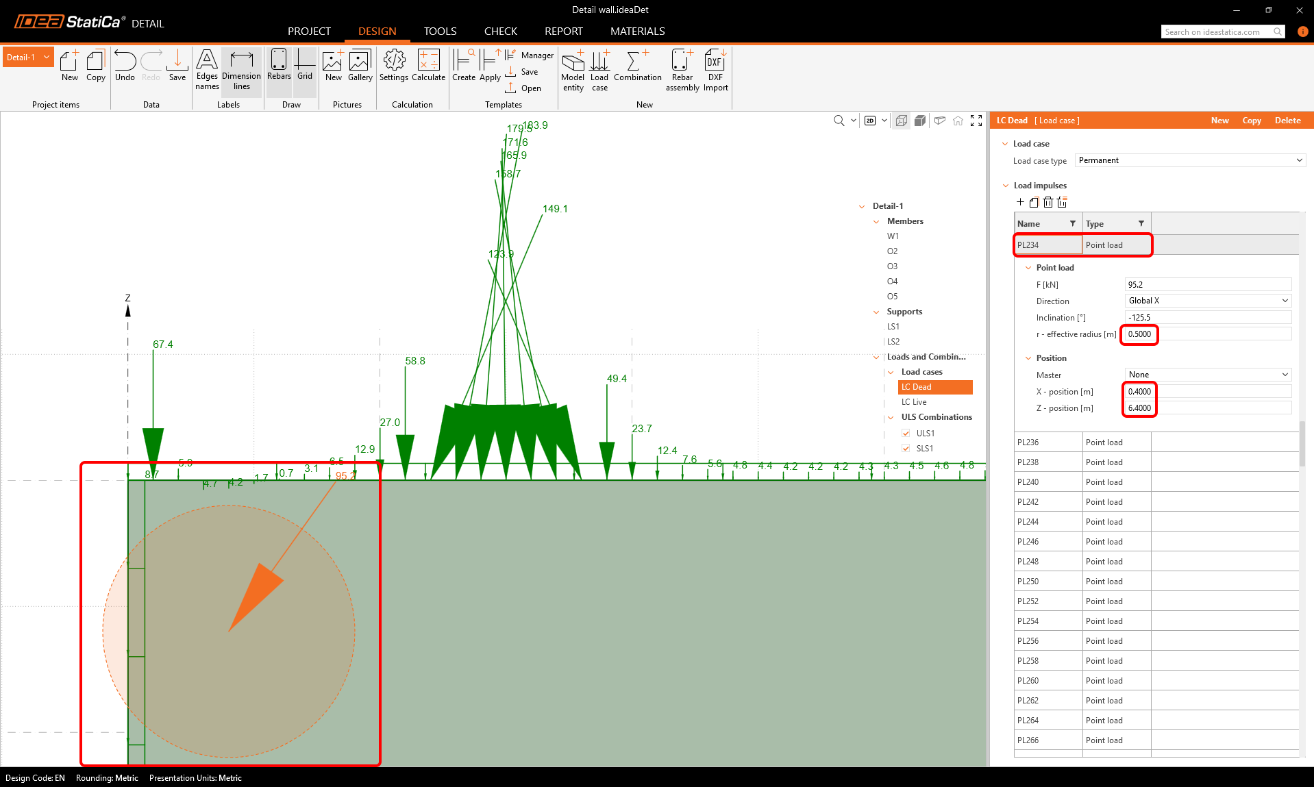
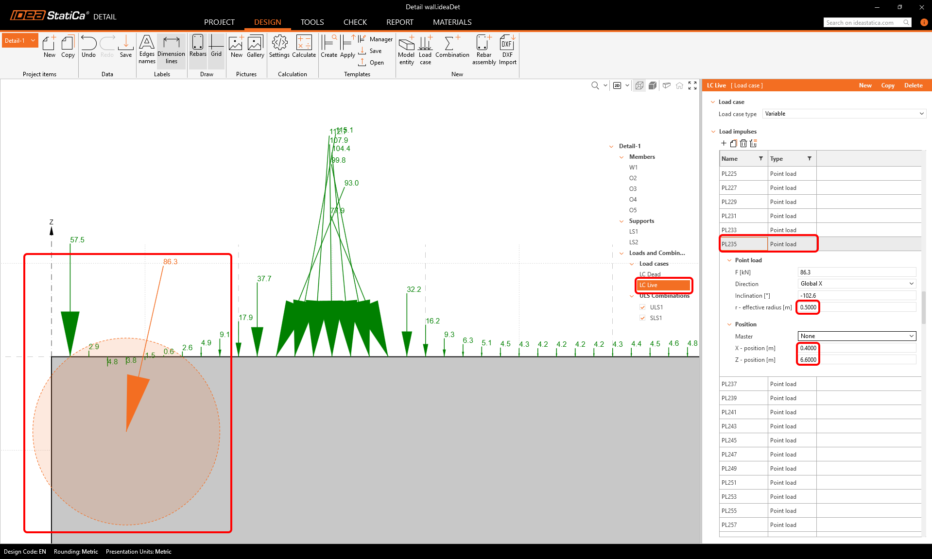
If we take a close look at the top left corner, we can see that there is a relatively large point load exactly on the corner of the concrete wall, directing outwards. Such a concentrated force placed on the corner could prevent the numerical calculation for converging, leading to unsatisfactory results.
To prevent this, we can move the point force a little more into the concrete wall, and increase the effective radius of the force.
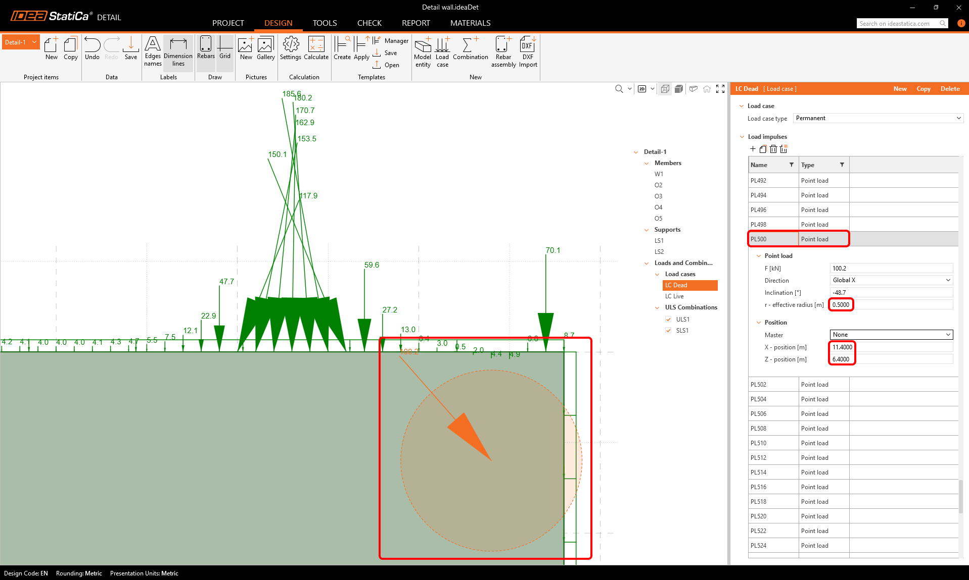
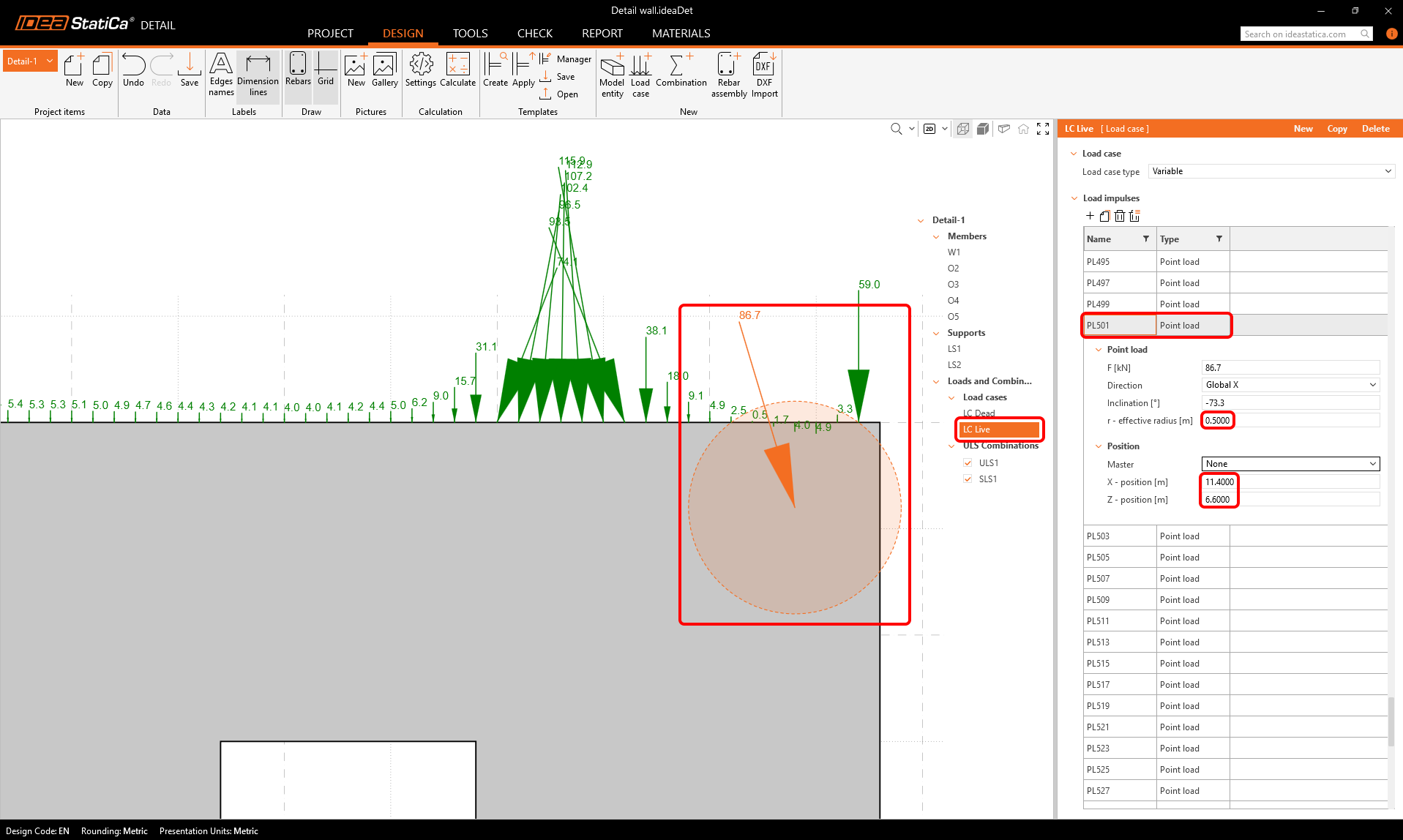
Doing the same on the top right corner.
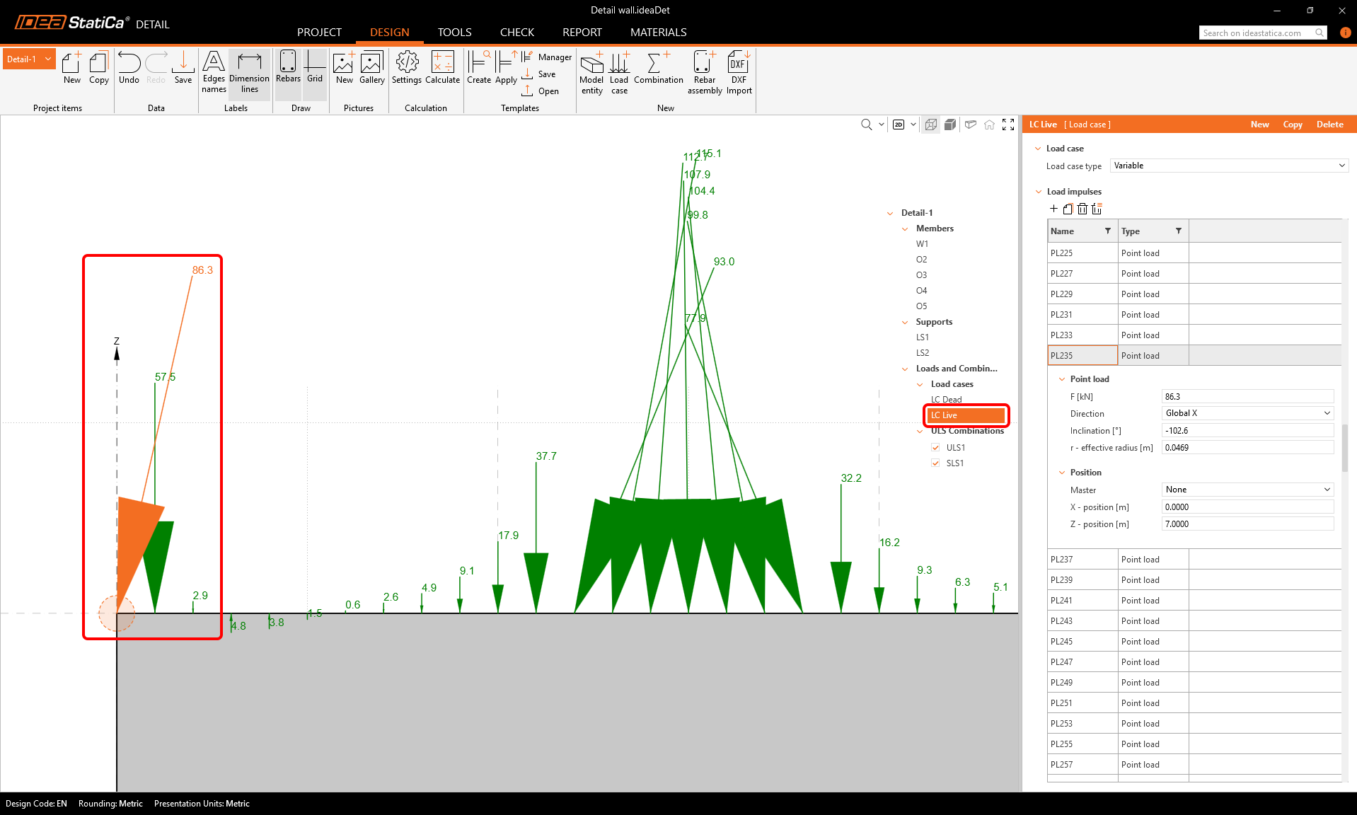
And for the second load case the same applies.
Combinations
We can see that there are two load combinations imported, by default both are set as ULS combinations.
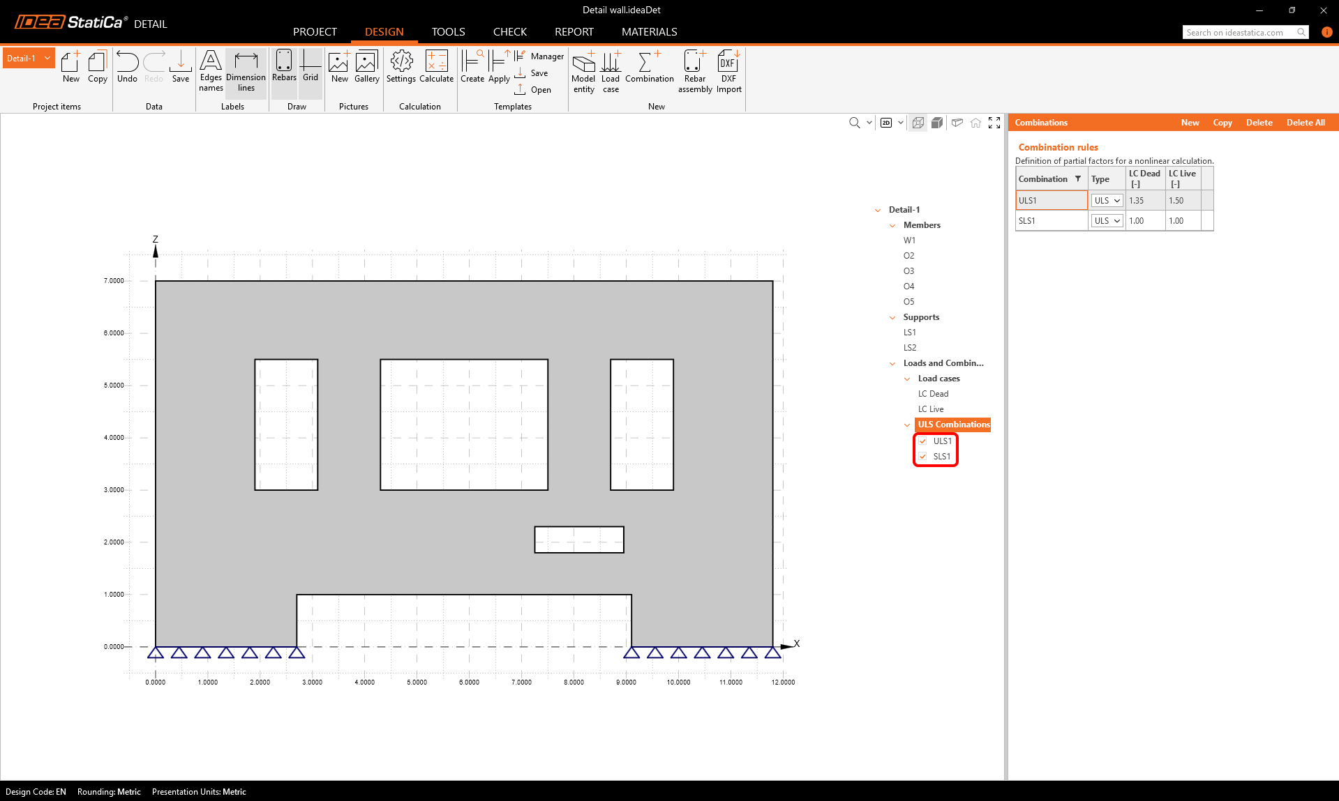
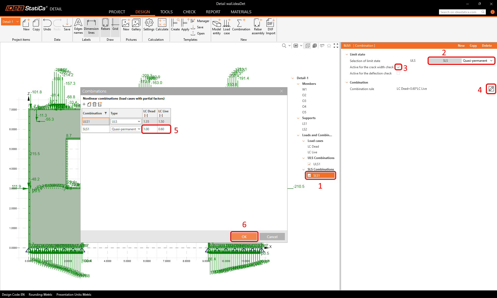
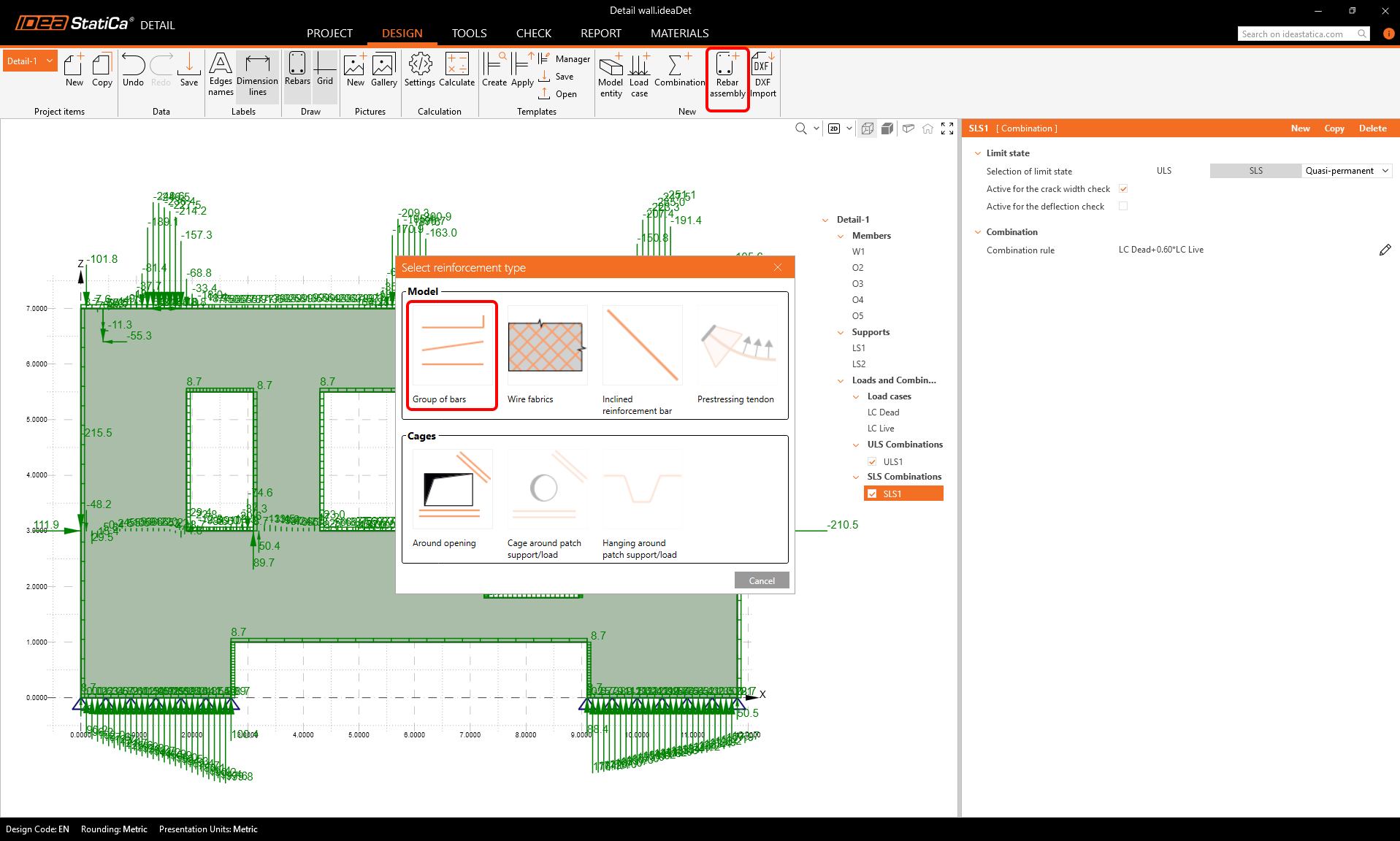
The second one should be an SLS combination. Let's change the settings of that combination, make it a Quasi-permanent one, active for crack width check, and set the load factors.
Reinforcement
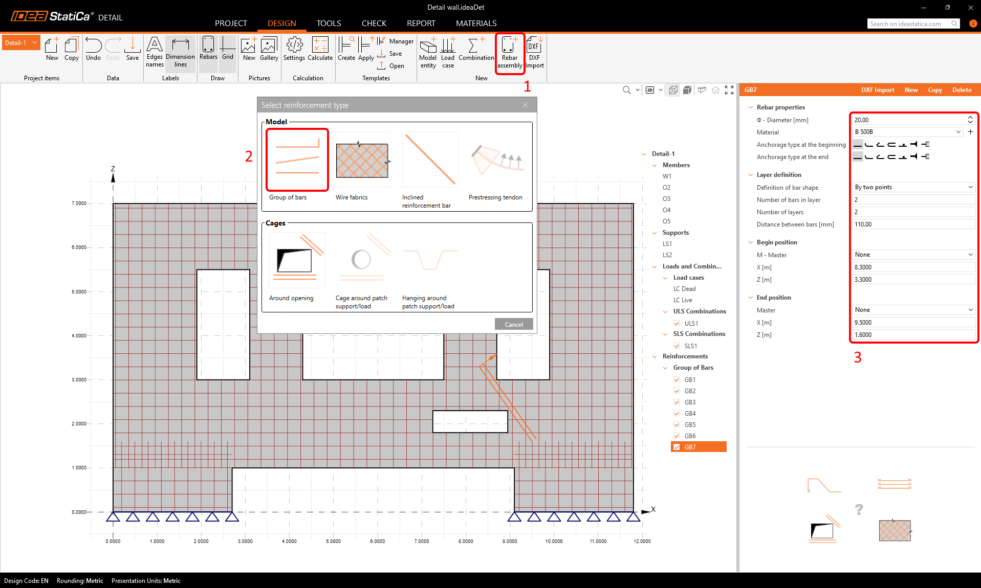
Now we can move on to inputting some reinforcement into the model. Let's click Rebar assembly in the ribbon and choose a Group of bars.
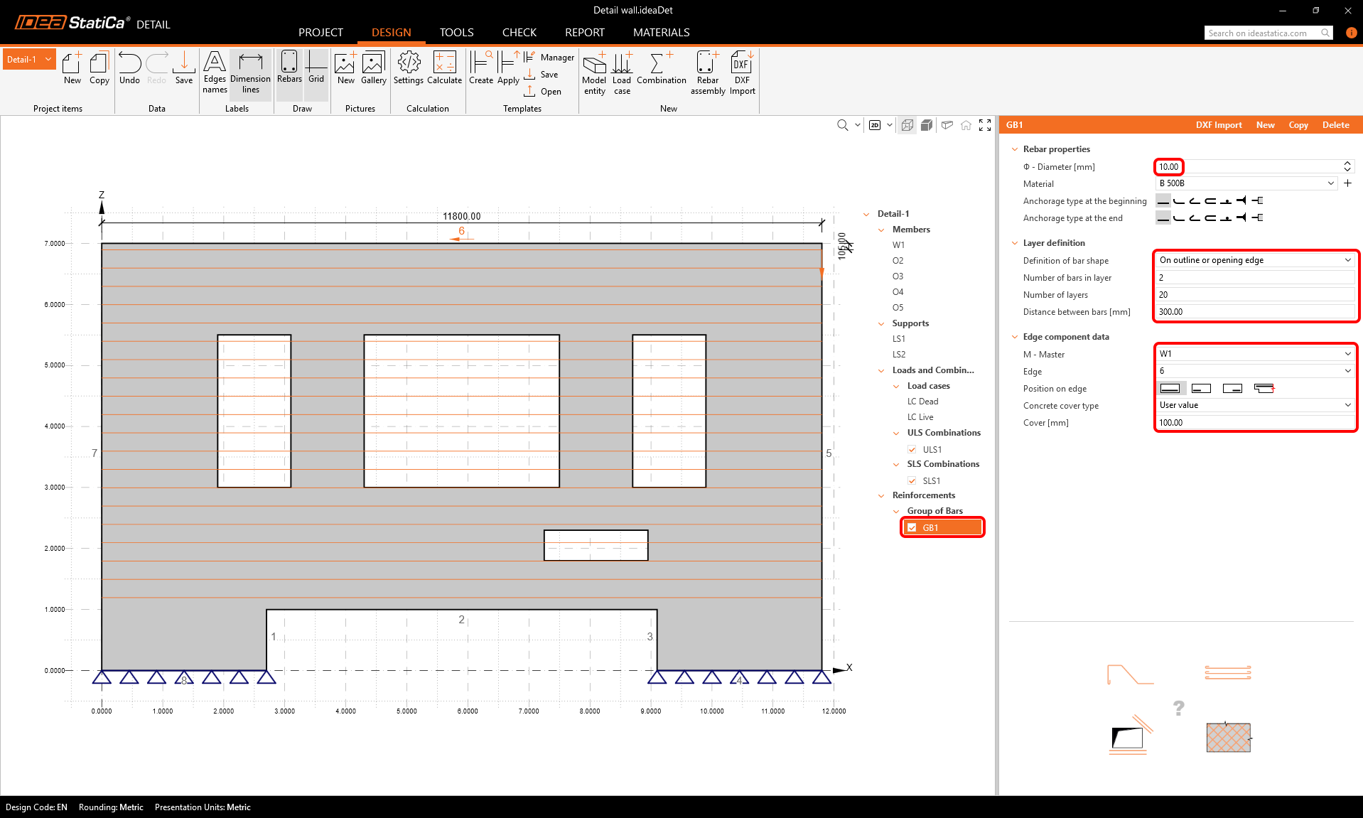
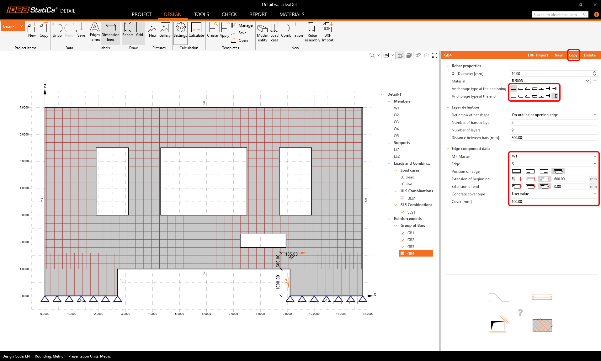
Define the properties of the reinforcement group like in the picture to input a group of horizontal bars into the wall.
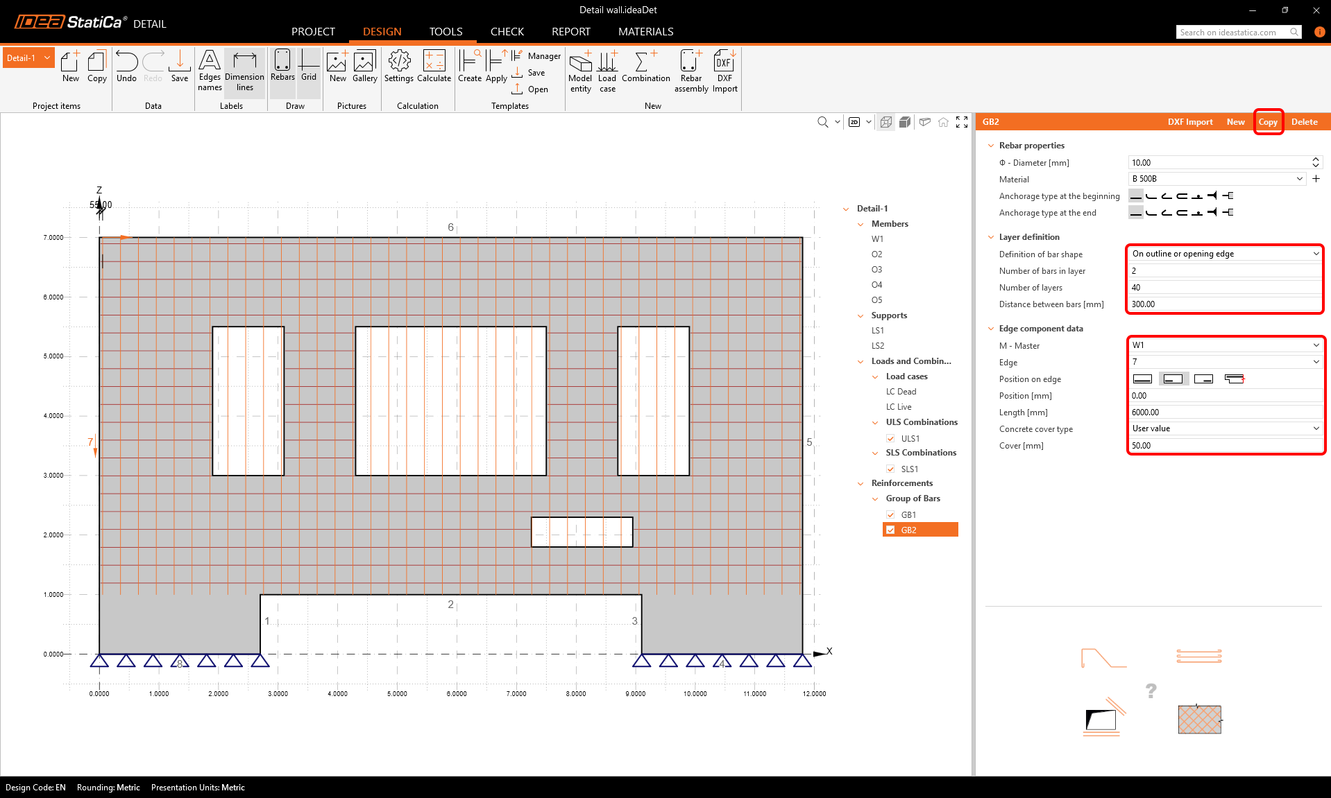
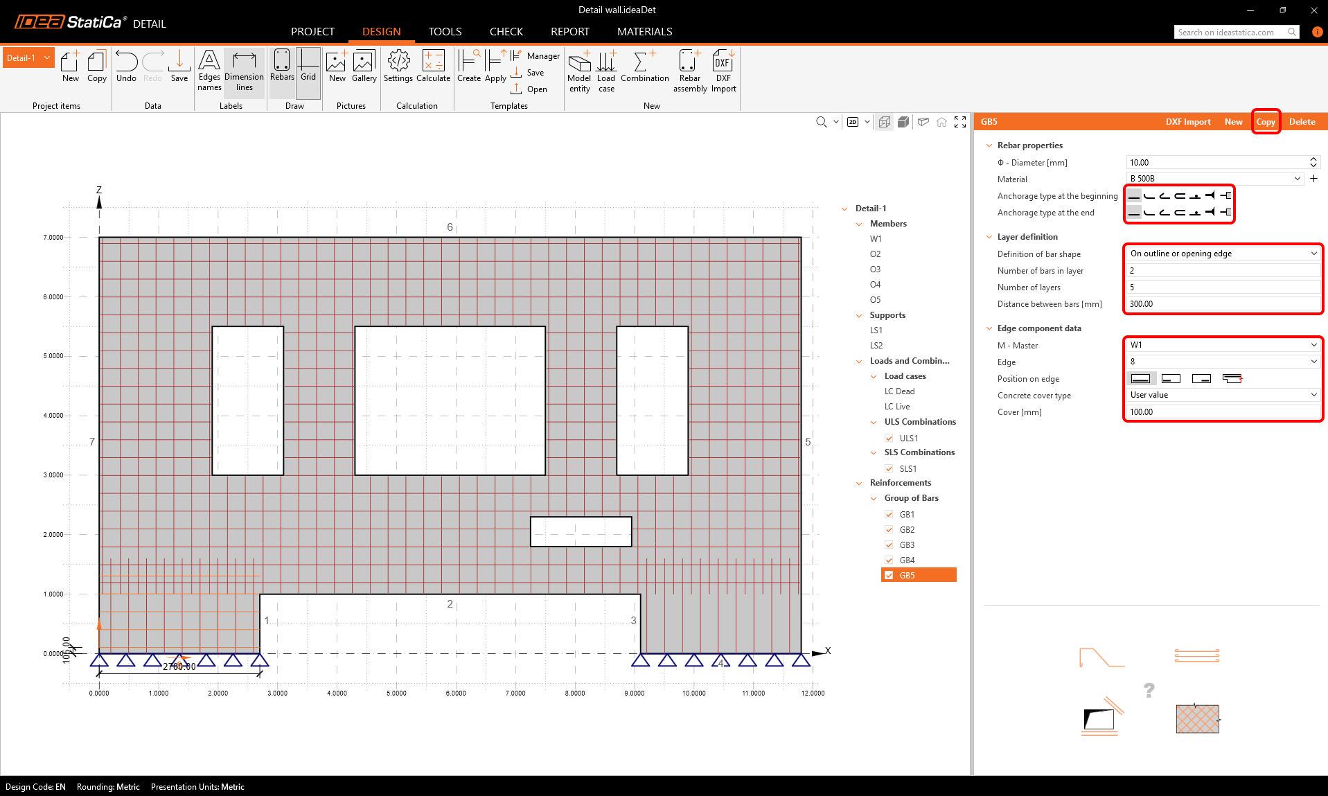
We can copy the first rebar group and modify the parameters to obtain a group of vertical bars.
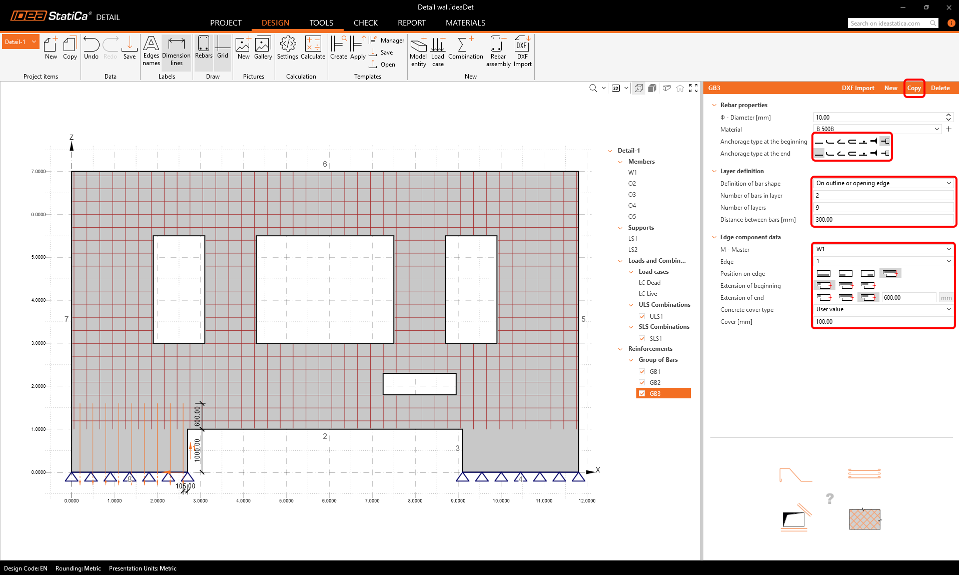
Let's copy again, and set the settings to create reinforcement into the lower left part of the wall.
Copy again, and create the lower right vertical bars.
Use the copy button two more times to input horizontal reinforcement into the lower parts of the wall.
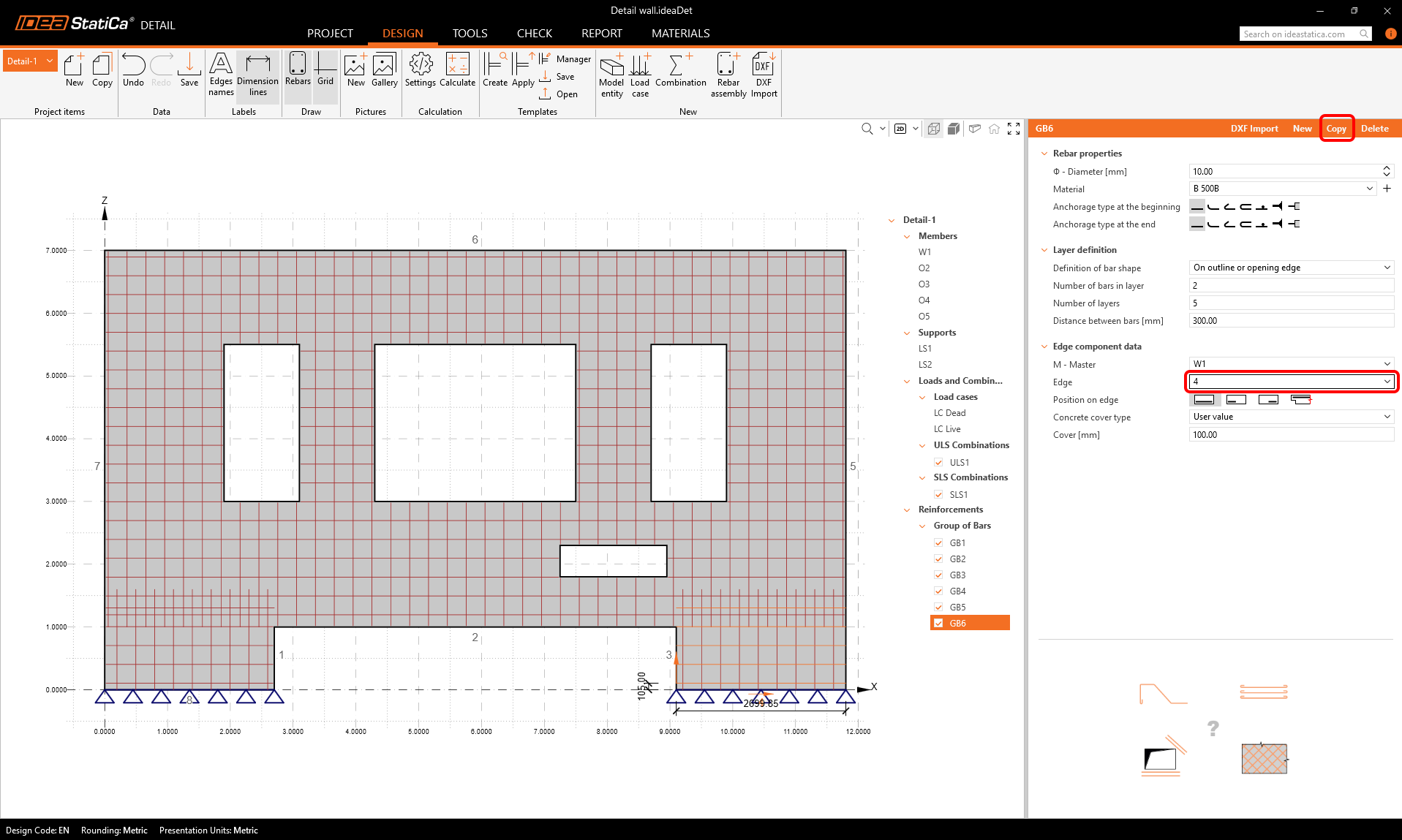
We should have 6 groups of bars at this point.
Calculation
We can now run a first calculation of the model to see how it behaves and where we should add reinforcement.
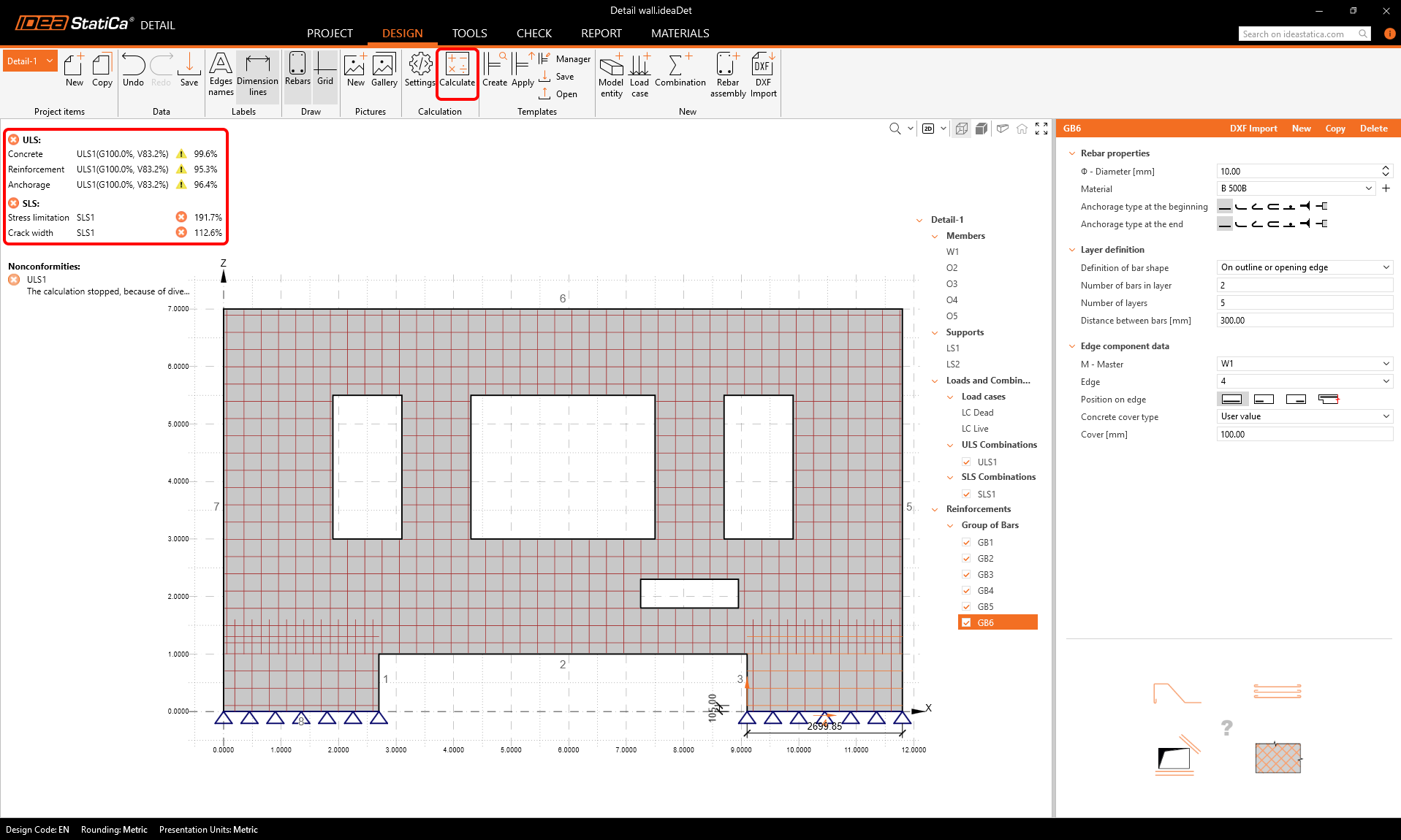
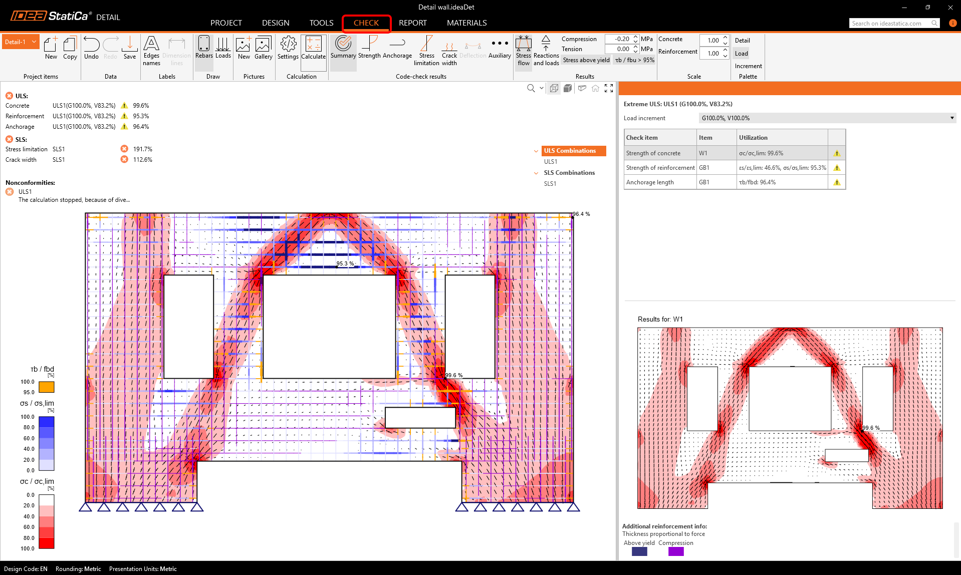
We can see from the summary of results that even the ULS checks failed, and the calculation could not finish successfully. Only a portion of the load was applied to the structure before failure. Let's find out the reasons and come up with a solution to fix this.
If we go to the Check tab, we can see the stress fields in the wall. There are some critical areas in concrete, where we can see big stress concentrations, marked with the red color.
If we go to the Strength results, we can display the kc2 factor. This is the compression strength reduction factor due to transverse strains in concrete. This phenomenon is also called compression softening. Find out more about our material models here.
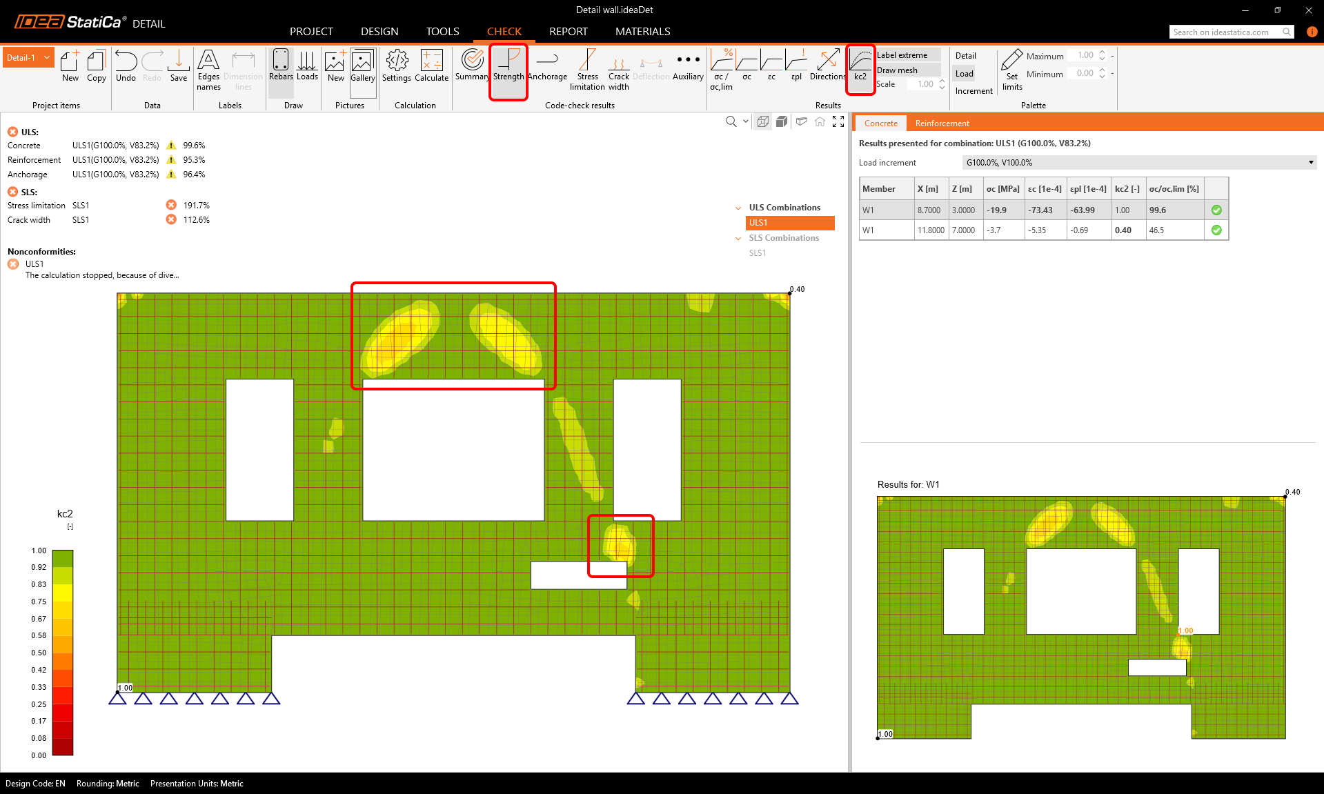
We can add reinforcement into the critical regions, where the compression softening has the biggest effect and the stresses are most concentrated.
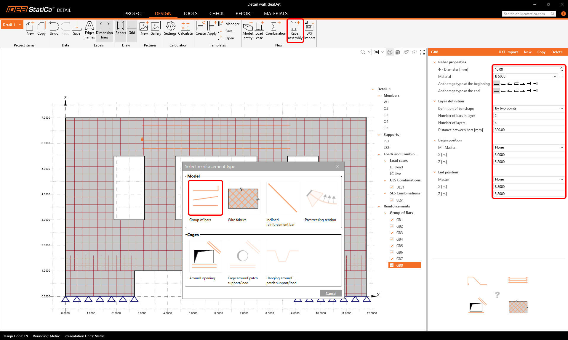
Let's add a group of inclined bars between the openings O2 and O5.
And also some horizontal reinforcement into the region above the opening O3.
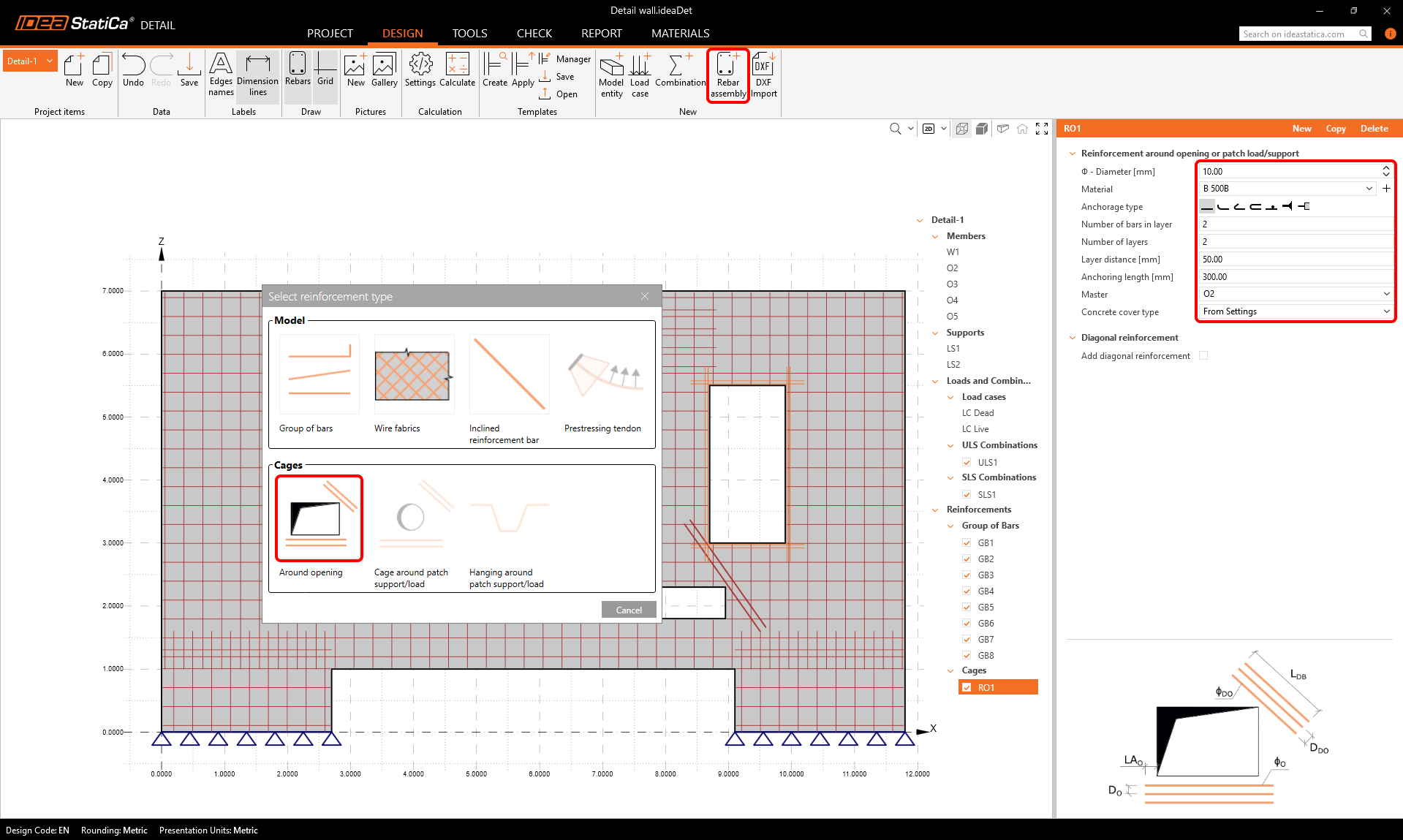
Around the openings, we should add reinforcement cages. Define the first set according to the picture.
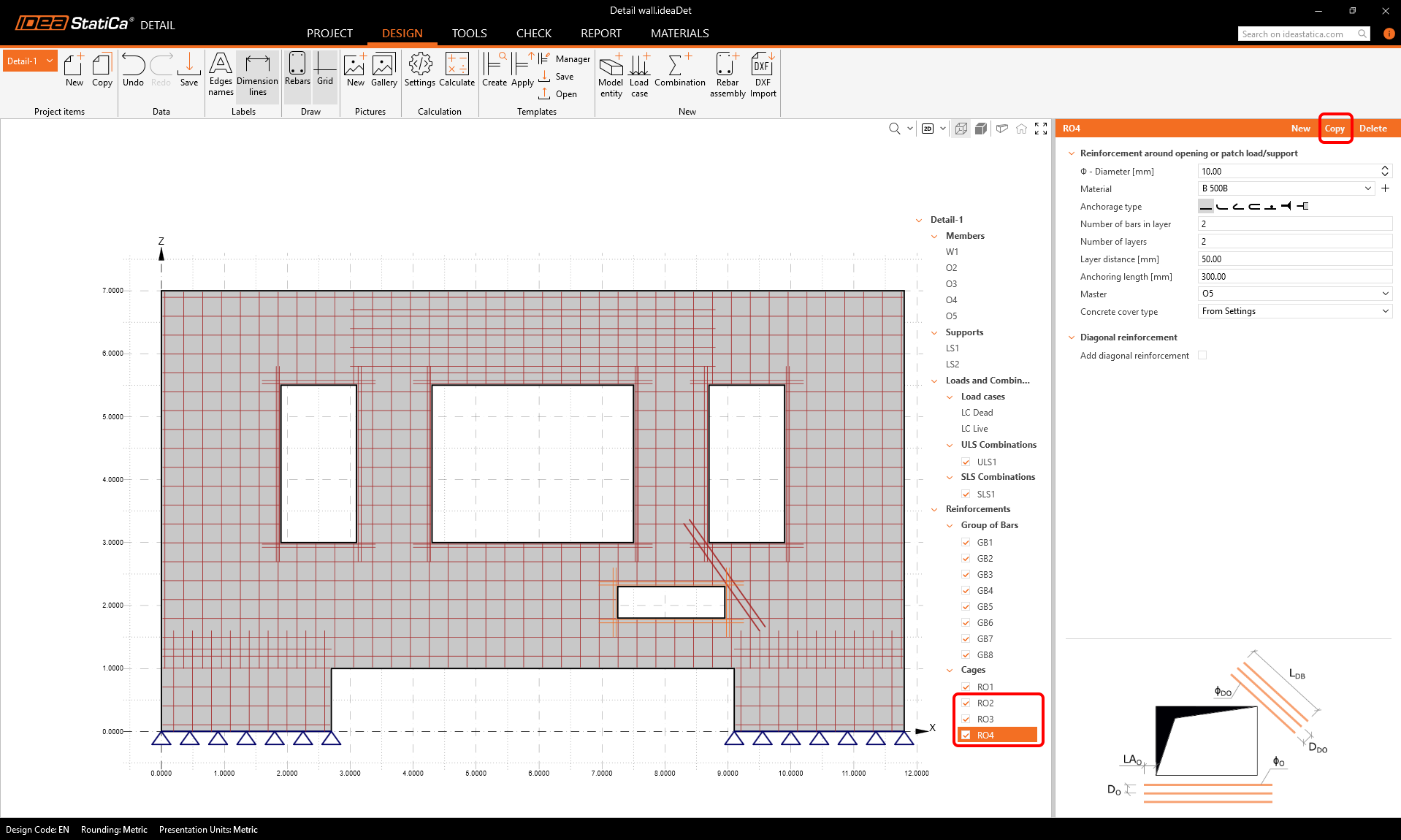
We can copy that first cage around opening onto the 3 other openings, and keep the settings the same.
Code-checks
Now, we can run the calculation again. The results show, that the ULS checks are now all passing the code requirements, and the crack width check in SLS is also within the limits.
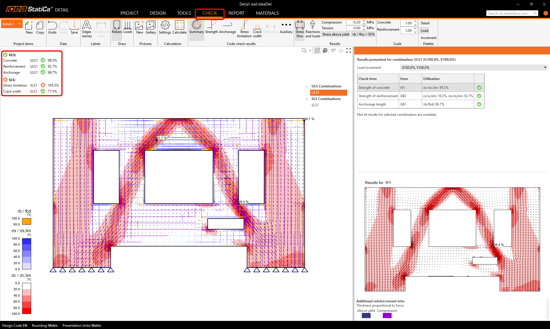
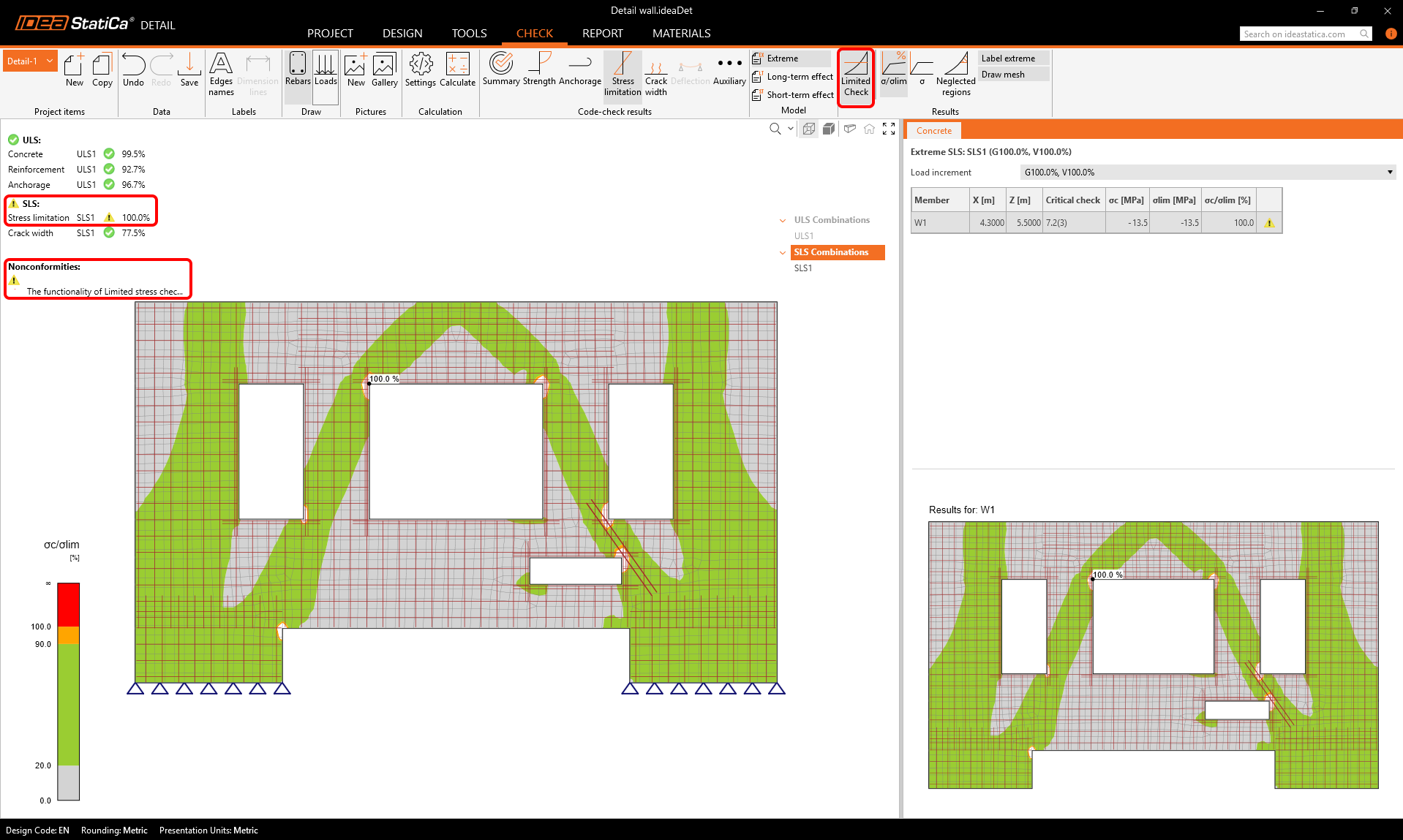
The only unsatisfactory check is the stress limitation check. We can display the results for it to see where the problems are.
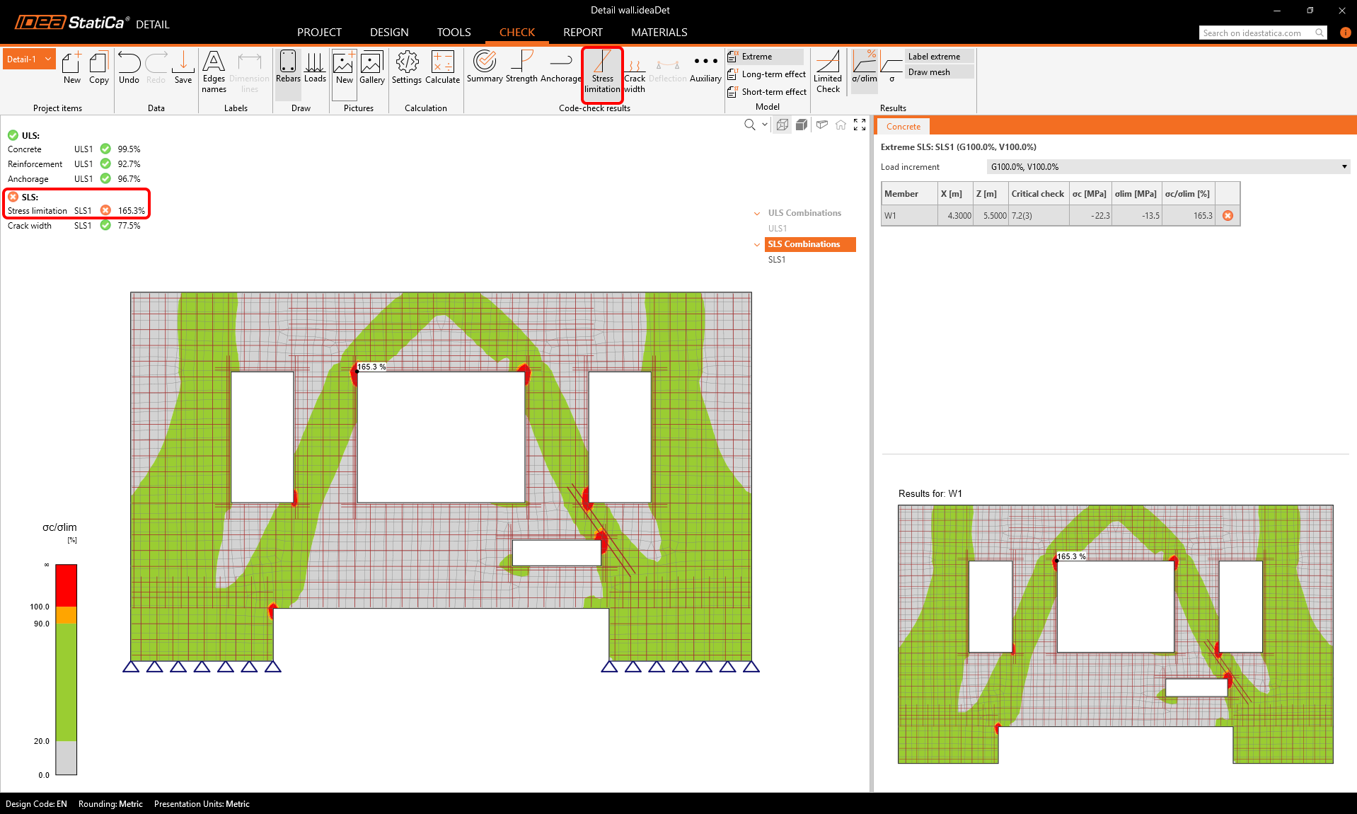
Because the stress in concrete exceeds the limit stress only in small regions around the sharp corners, we can turn on the Limited Check functionality in the top ribbon. In numerical calculations, it is typical that stress peaks (singularities) form around sharp corners. In such cases, we can exclude those areas from the code-checks. This means that we will see 100% results for the stress limitation check, completed with a nonconformity message that explains the usage of limited checks. Find out more about the Limited Check in this article.
Report and Bill of material
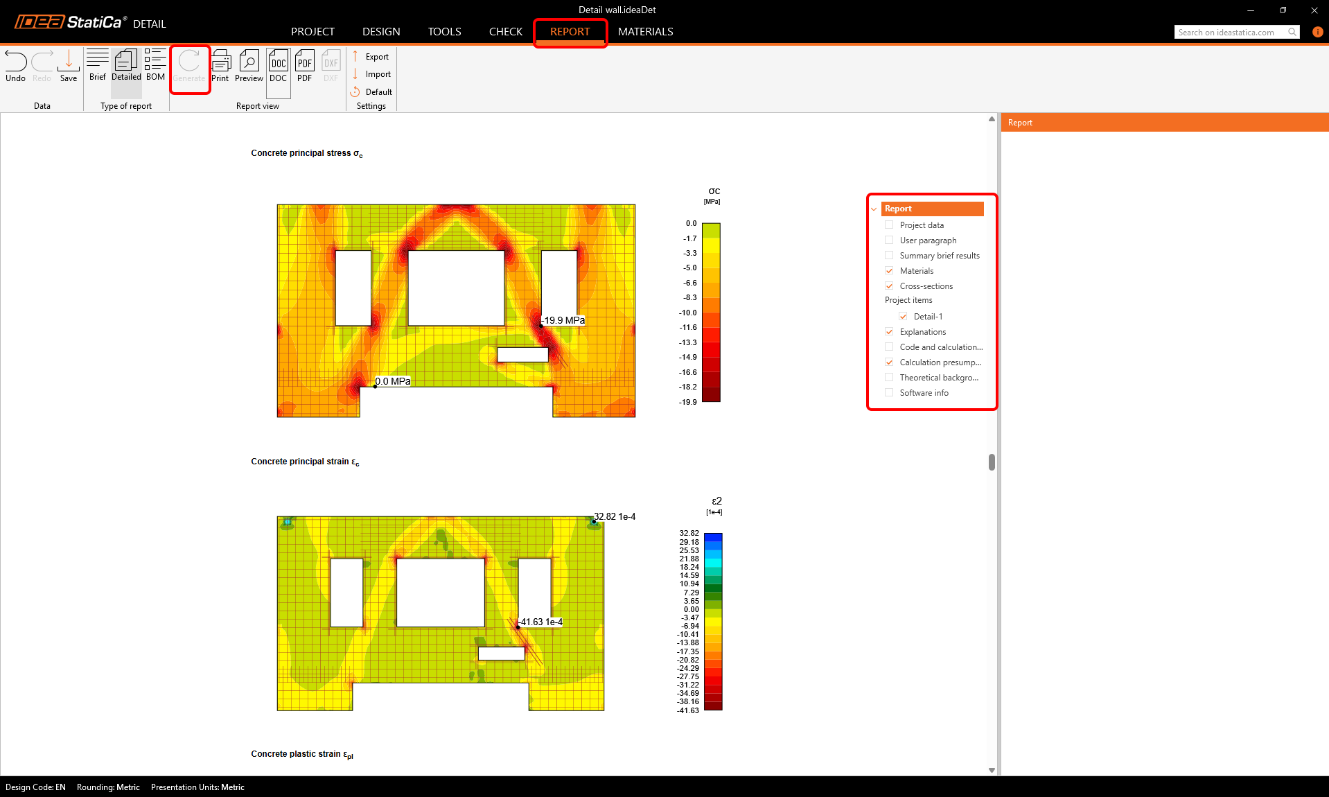
Now, we can generate a customizable Report that can be printed or exported as a PDF or DOC.
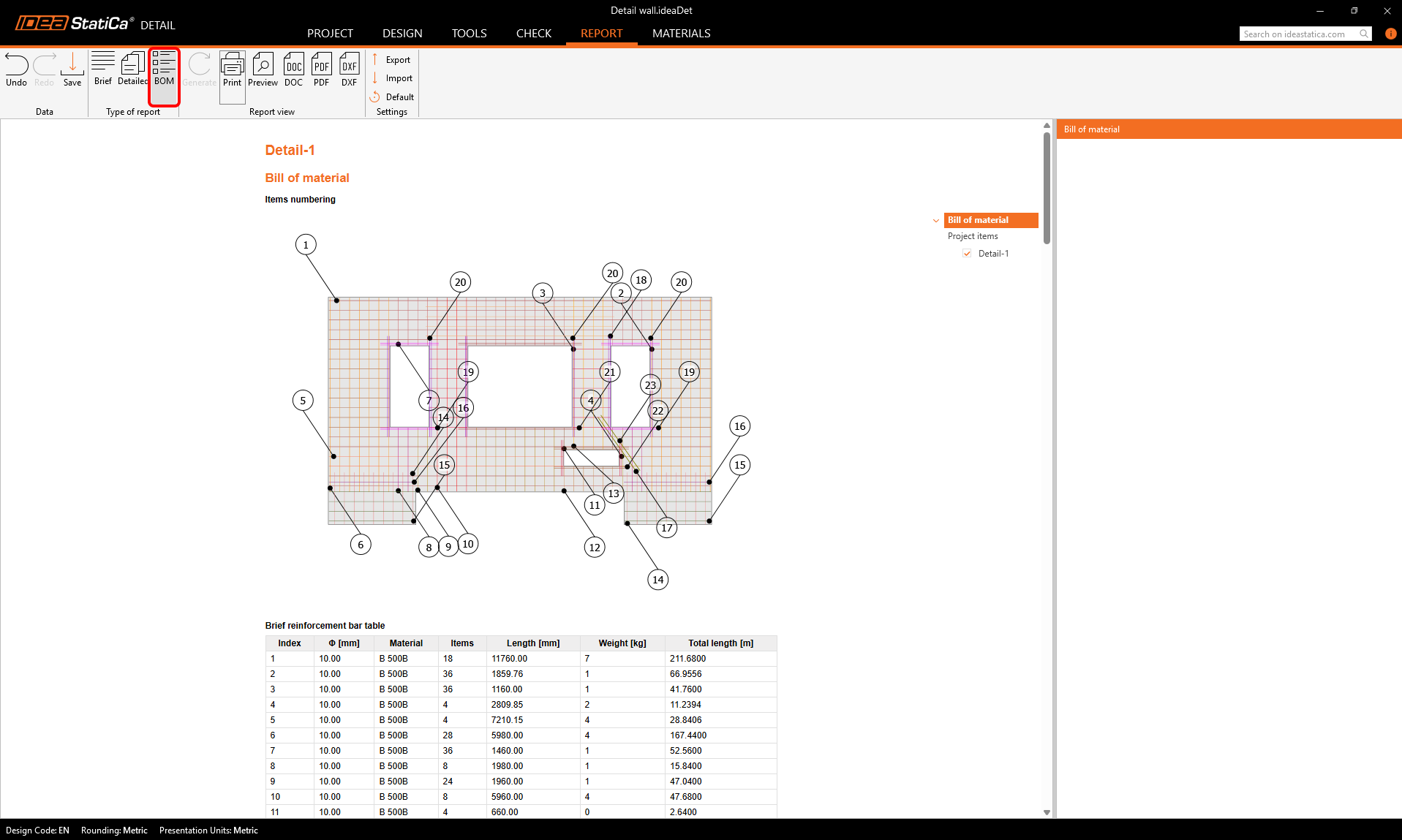
The Bill of material can also be generated, and we can export it as a DXF.
We have successfully imported, designed, and checked a reinforced concrete wall with openings from ETABS.
To learn about the whole workflow, the force transfer and the known limitations, read this article.
Attached Downloads
- ETABS-Detail.zip (ZIP, 18.8 MB)