
ETABS and SAP2000 BIM link to Detail
This link addresses the need for efficient continuity between global analysis and detailed reinforced concrete design. While ETABS and SAP2000 are primarily intended for global structural analysis based on the Bernoulli–Navier hypothesis (plane sections remain plane), regions with discontinuities require a more advanced analytical approach. The Compatible Stress Field Method (CSFM) implemented in IDEA StatiCa Detail is specifically designed to analyze these regions, capturing nonlinear and localised behavior with higher accuracy.
Without this link, engineers must manually rebuild wall models and reapply loads in IDEA StatiCa Detail. Once transferred, Detail provides advanced nonlinear analysis, reinforcement design, and code checks, extending the capabilities of ETABS and SAP2000 beyond global behaviour to local structural verification.
This link is available for all versions of ETABS and SAP2000, supporting design codes for EC, ACI, and AUS.
ETABS to Detail Workflow steps
To enable export from ETABS, add the IDEA StatiCa plugin used for both steel and concrete workflows. To add the plugin, navigate to the “Tools” tab in ETABS or SAP2000, then select Add Plugin. The plugin file can be found at:
C:\Program Files\IDEA StatiCa\StatiCa 25.1\net48\IdeaETABSv1PluginWrapper.dll
- Prepare the Model: Run the analysis in ETABS or SAP2000 for all required load cases and combinations.
- Activate BIM link: Launch Checkbot by activating the plugin in ETABS or SAP2000. Create a new concrete project.
- Import Walls: Choose the wall elements to import. Other selected items might also appear in Checkbot.
- Create Details: Use Detail+ to create Detail elements. Select wall elements in the 3D scene and confirm.
- Export to Detail: Export the selected detail elements as a Detail model.
- Design in Detail: Open the model in Detail 2D and add supports to match the geometry defined in ETABS, using either boundary conditions or wall connections as appropriate.
- Add reinforcement: Define reinforcements based on stress flow.
- Analyse: Run the calculation and investigate the results.
- Report: Create a report.
For detailed steps, please follow this tutorial.
Force transfer process
Transferring internal forces in 2D elements is a complex process that can differ between software applications. For this reason, our initial focus has been on ETABS. In this section, we explain the background and methodology for transferring forces between ETABS and IDEA StatiCa Detail 2D.
The basic process is outlined below:
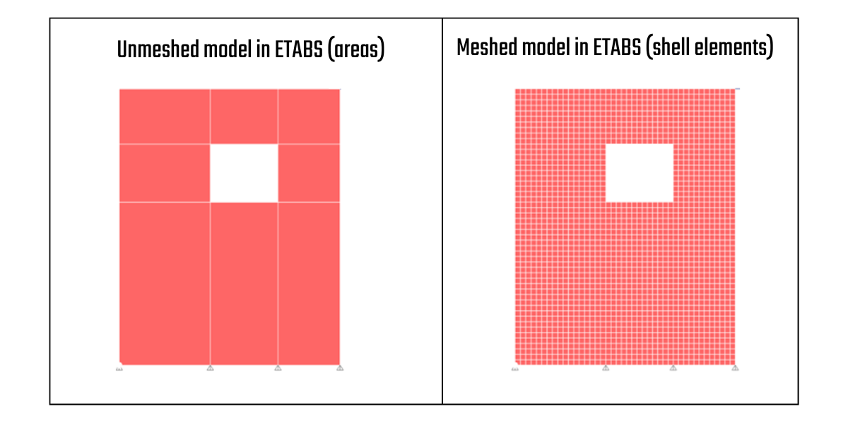
- Shell Force Extraction
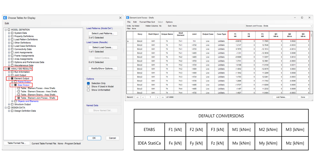
Joint forces from shell elements in ETABS are obtained using the Element Joint Forces – Shells output table.
To access these values in ETABS:- Select the wall elements in the 3D view.
- Navigate to:
Display → Show Tables → Analysis Results → Element Output → Area Output → Table: Element Joint Forces – Shells
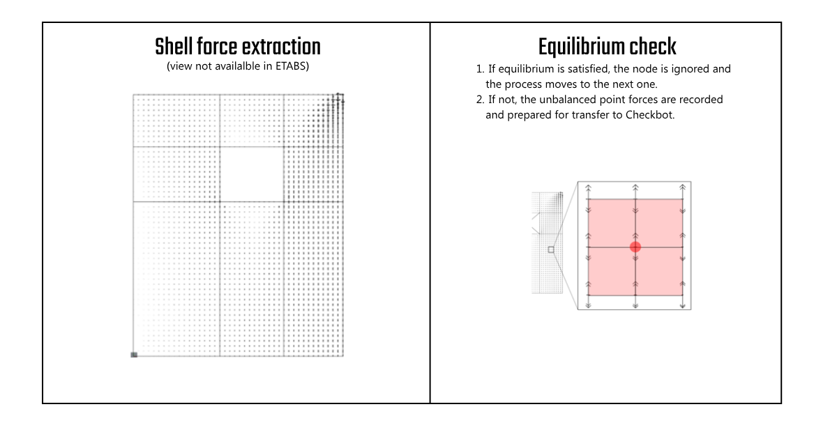
- Equilibrium check
For each shell, at each joint, the corresponding shell forces are evaluated for all six degrees of freedom to check whether equilibrium is achieved.- If equilibrium is satisfied (i.e., the sum of forces and moments equals zero), the node is ignored and the process moves to the next one.
- If not, the unbalanced point forces are recorded and prepared for transfer to Checkbot.
- Joint force moments (M1, M2, M3) are excluded from the equilibrium calculations.
- Typically, joints that are not in equilibrium are located along the edges of the area elements. However, internal joints may also show imbalance in certain cases, such as when area elements are not pre-meshed at slab intersections or when individual point loads are applied directly to a joint.
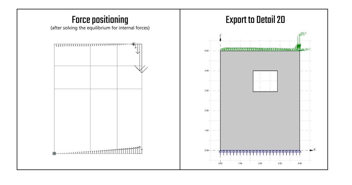
- Force positioning
The resultant joint forces are then assigned at a specified 2D X-Y coordinate on the area panel in the Detail view. These forces are subsequently transferred to Checkbot, where they are stored and prepared for export to Detail 2D.
- Additional Load Transfer
Certain loads acting on or within the area element are not captured by the joint force equilibrium method and must be transferred using an alternative approach to maintain consistency between ETABS and Detail 2D. These include:- Self-weight of the element – If self-weight is defined in ETABS for a given load pattern, it is calculated automatically and saved to the corresponding load case in Checkbot. It is then applied to the Detail 2D member as a uniform load.
- Uniform area loading – Any uniform load applied to an area element in ETABS is saved to the load case and automatically transferred to the Detail 2D member as a uniform load.
- From the user’s perspective, there is no difference in workflow, these loads are managed automatically within the transfer process, requiring no additional input or action.
Known limitations
Refer to the article: limitations for the BIM link between ETABS, SAP2000, and IDEA StatiCa for concrete wall design in Detail.