CSFM explained
In practice, the Strut-and-Tie (S&T) and Stress Fields Methods are standardly used to design discontinuity regions in reinforced and prestressed concrete structures. The Compatible Stress Field Method (CSFM) was developed by extending these classical theories, allowing a high degree of automation and is consistent with the design standard. Despite its simplicity, the method provides a very realistic description of the response of a concrete structure both in the ultimate limit state (ULS) and serviceability limit state (SLS). The CSFM is implemented in IDEA StatiCa Detail.
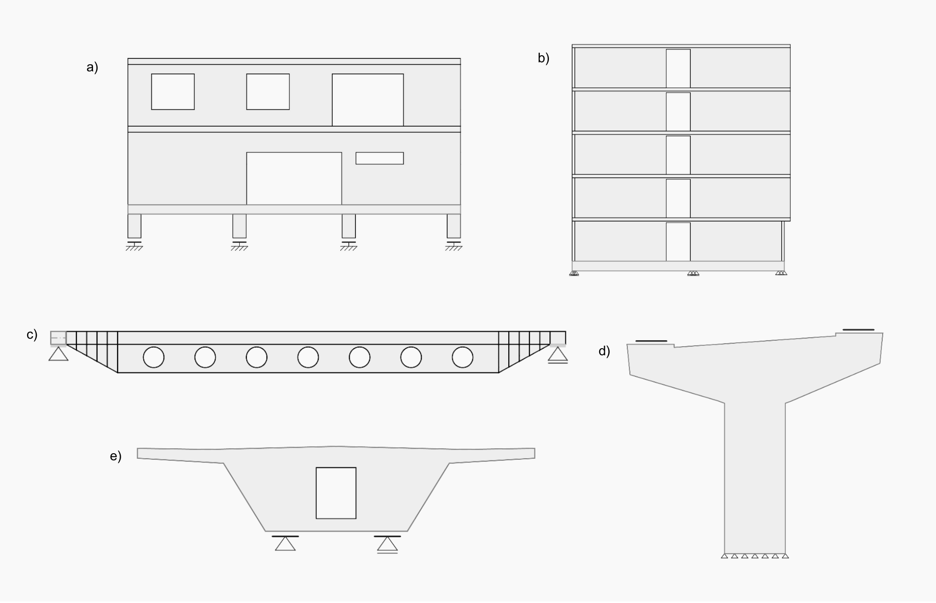
Fig. 1 a) Wall with openings b) Shear wall c) Beam with dapped ends and openings d) Bridge pier e) Bridge diaphragm
Standard procedures for designing cross-sections of concrete structures are applicable in parts where the Bernoulli-Navier hypothesis of plane strain distribution applies (region B). The places where this hypothesis does not apply are called discontinuity regions (D-Regions). These include parts of structures where concentrated loads appear or where there is a sudden change in cross-section, such as dapped ends (Fig. 1c), deep beams, walls with openings (Figs. 1a, 1b), or corbels and pile caps. In the field of bridge engineering, these are e.g. pier caps (Fig. 1d), diaphragm (Fig. 1e), deviators, etc.
1. Strut and Tie Method
The basic assumption when defining an S&T model is that the tensile strength of concrete is neglected. A simple truss model consists of elements acting in compression and tension, representing ULS behavior. In general, this is not a complex problem, and defining a basic S&T model (Fig. 2a) should not be a problem for an experienced engineer. However, even for this basic task, the correct assessment of the model in accordance with the design standard can be a tedious, manual, and iterative process.
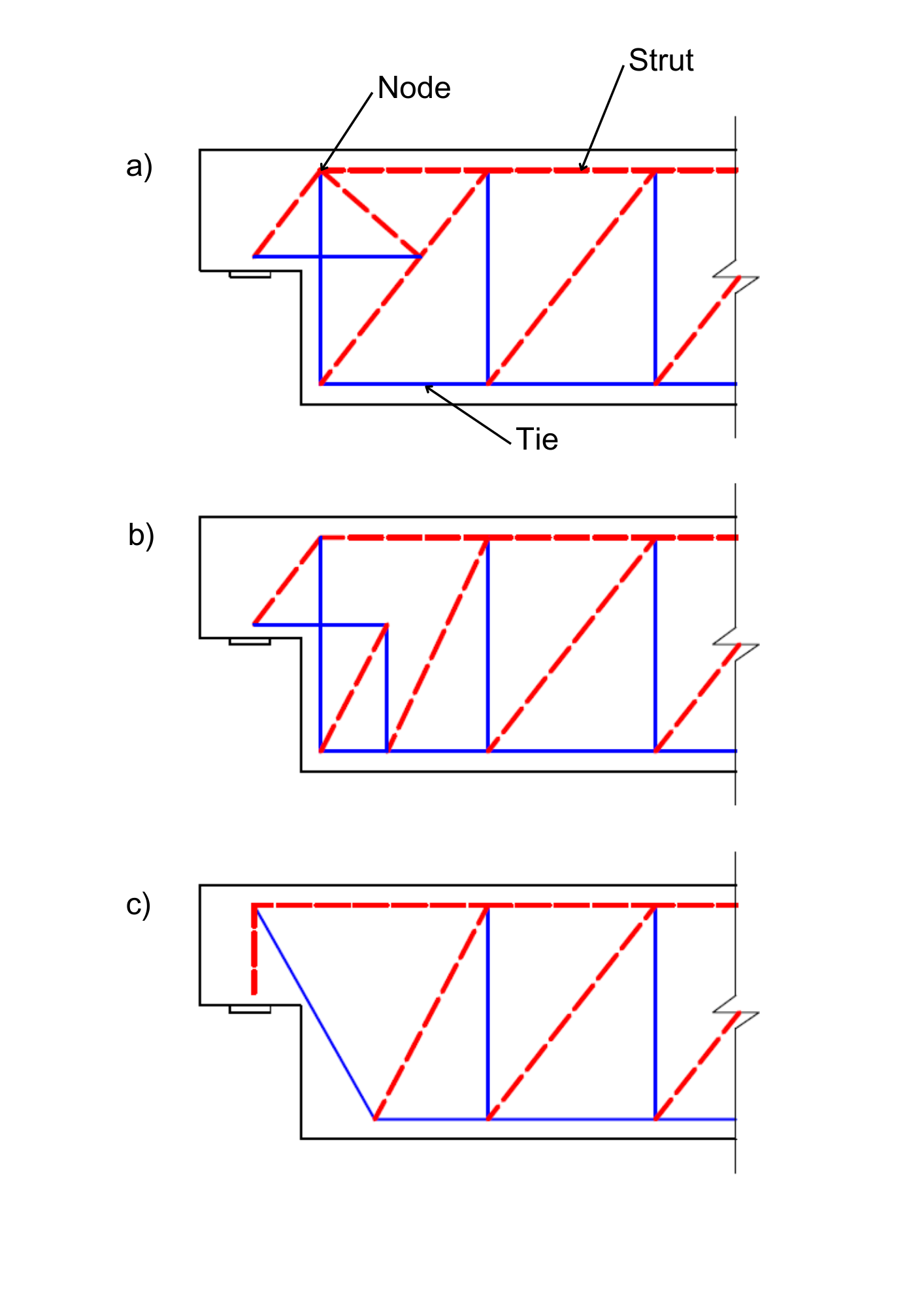
Fig. 2 a) S&T model option 1 b) S&T model option 2 c) S&T model option
Ties, nodal areas, and transverse tensile strain in struts must be assessed. If the model does not pass the check, a S&T geometry must be adjusted, or a different S&T model must be selected (Fig. 2b, 2c). This often leads to the structural engineer choosing the S&T model geometry only once and assessing only the rebar. This can lead to a substantial error. The choice of model is always a matter of experience. For more complex structural details, choosing a S&T that will sufficiently match the actual behavior of the structure may not be as easy as in the case above. Also, the S&T is a method for the design of ultimate limit states only. It does not allow the design of serviceability limit states (deformation, cracking), which are critical criteria, especially in structures of significant importance, as they directly impact the structure's service life.
2. Compatible Stress Field Method - CSFM
CSFM is a modern nonlinear method for the analysis of D-regions and elements whose behavior can be simplified to plane stress, i.e. a 2D model. However, it is still based on a basic and safe assumption of the standards: concrete does not act in tension, and all tension must be transferred by reinforcement. The Compatible Stress Field Method (CSFM) is an evolution of the S&T and stress field methods, removing their main disadvantages mentioned above: uncertainties in model selection, difficulty in automation and inability to assess serviceability limit states.
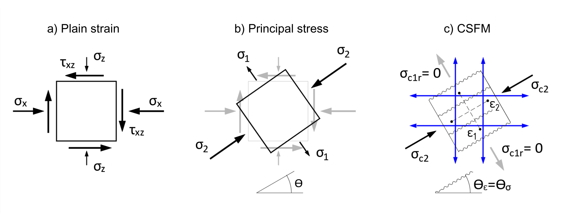
Fig. 3 a) Plain strain b) Principal stress c) CSFM
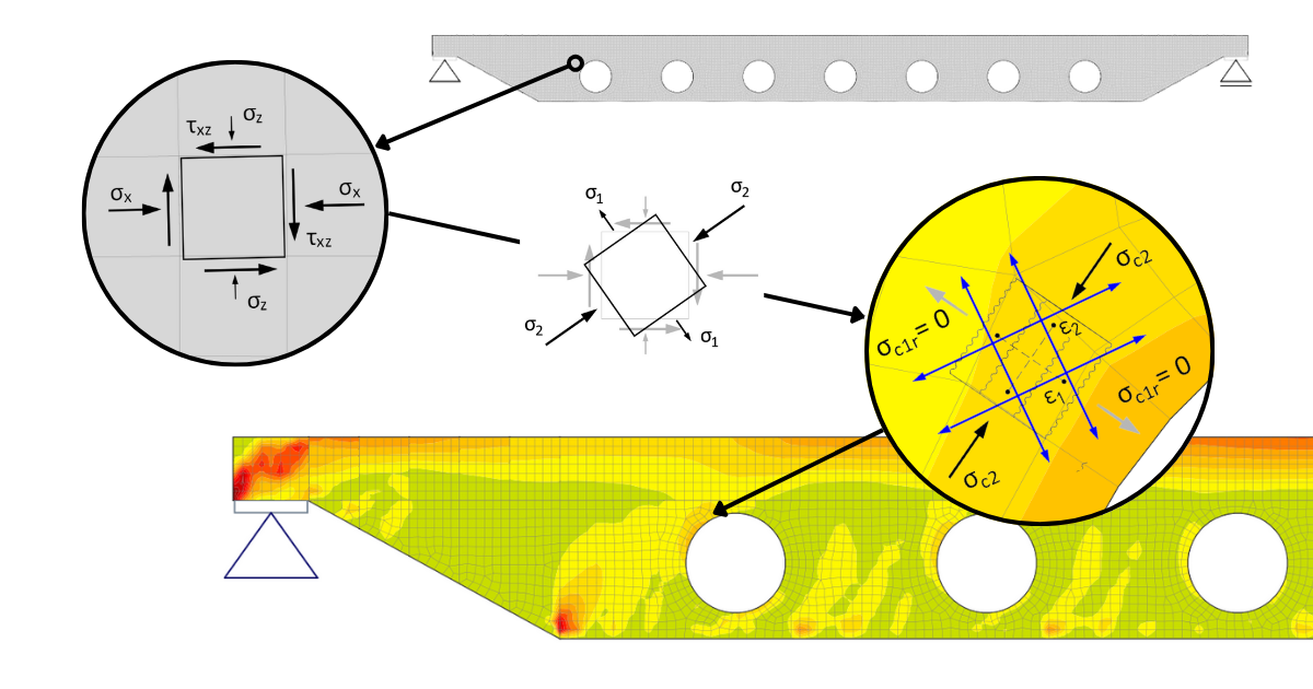
The principle of CSFM can be explained on the plain stress of the basic plane element of a reinforced concrete structure. Fig. 3a shows the basic 2D element in plain stress as we know it from all textbooks on elasticity and strength. This is the stress at one point in the structure, obtained, for example, by linear elastic analysis using the finite element method (FEM). The element is subjected to a horizontal normal stress σx, a vertical normal stress σz, and a shear stress τxz. From these stresses, the so-called principal stresses and their direction defined by the angle θ can be determined (Fig. 3b). The element is then subjected to the principal tensile stress σ1 and the principal compressive stress σ2.
What will the strain of the same element analyzed by CSFM look like? The strain is shown in Figure 3c. The compressed concrete appears in the direction of the principal compressive stress σ2. And a stress field with stress σc2 is generated. As mentioned above, the basic assumption is that the concrete does not act in tension. Therefore, the transverse principal tensile stress σ1 will not be transferred by the concrete, and a crack will form perpendicular to the direction. The stress σc1r must therefore be zero. To avoid the failure of our 2D element, all tensile stress must be transferred by the reinforcement (indicated in blue in Fig. 3c), which must be part of the computational model.
If this stress analysis is performed using CSFM continuously over the entire 2D region to be solved, the result is a continuous compression field in concrete plus tensile an compression stresses in the reinforcement. A simplified graphical representation of the CSFM stress field is shown in Figure 4. In addition to the concrete and reinforcement utilization rates, the figure also indicates the varying directions of the calculated stresses σc2 along the regions.
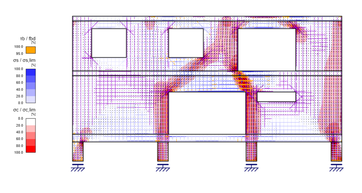
Fig. 4 Overall results from IDEA StatiCa Detail
The analysis of a detail or structure using CSFM is based on the finite element method. The concrete is modeled using 2D wall elements, and the reinforcement using 1D member elements (Fig. 7). The analysis is not performed in one step since it is a nonlinear problem. Loads are applied in increments during the calculation, and the solution to the nonlinear system of equations is found using the Newton-Raphson method.
The fictitious smeared cracks (ε1 is the average value) are "formed" perpendicular to the direction of the principal stresses, which may change during the nonlinear calculation as the element "progressively cracks" from each increment of load. In summary, a fictitious stress-free rotating crack is considered.
The result of the FEM solution using CSFM is a compatible stress field (i.e., the concrete does not break into individual independently acting struts in the model) and the state of strain, that are continuous throughout the 2D domain being solved. This is a major advantage over classical S&T approaches and allows the computational model to be automated and refined, as described in the following paragraphs.
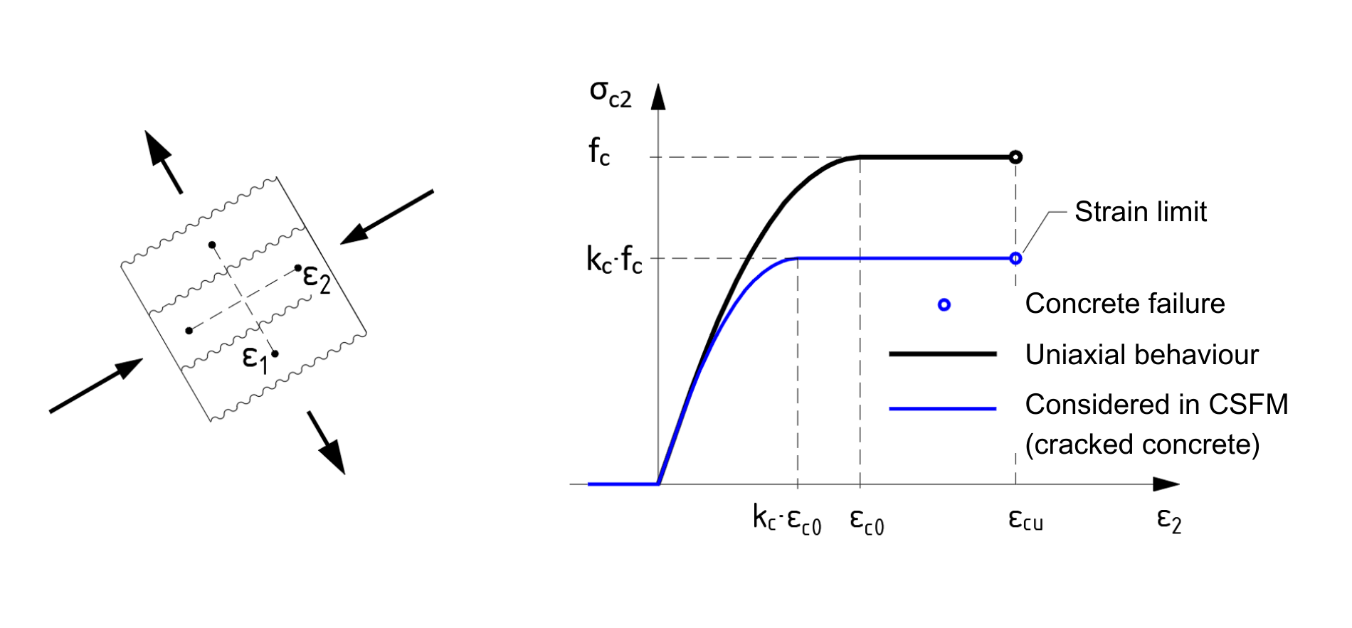
Fig. 5 Princip of concrete softening
The simple formulation of the CSFM allows using the standard uniaxial parabolic-rectangular stress-strain diagram for concrete in compression according to the design standard. As is well known, the compressive strength of concrete decreases when the concrete is damaged by transverse cracks (Fig. 5). This so-called compression softening effect is included in the method by automatically taking into account the effective compressive strength of the concrete.
Based on the level of transverse tensile strains ε1, the reduction factor kc is determined and the stress-strain diagram of the concrete is adjusted (Fig. 5). As the field of strains throughout the structure is known, the effective compressive strength of the concrete can be calculated automatically in individual sections depending on the local level of transverse tensile strains ε1.
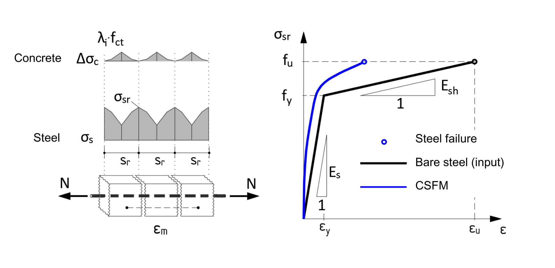
Fig. 6 Princip of tension stiffening
Furthermore, the CSFM considers the stiffening effect of the tensile concrete between the cracks on the reinforcement, so-called tension stiffening. In the calculation model, the average reinforcement ratio εm is used. Then the reinforcement stress-strain diagram is modified (Fig. 6). This allows a realistic representation of the stiffness of a reinforced concrete structure damaged by cracks. However, it is still true that the tensile strength of concrete does not contribute to the ultimate capacity. The maximum stress in the reinforcement σsr in the cracks is critical for the design (Fig. 6).
CSFM uses common uniaxial material models (stress-strain diagrams) defined in design standards. The standard approach, the partial safety factor method, is then used to assess the ULS. The simplicity of the method makes it suitable for engineering practice and is consistent with the design standards.
Even though it is a nonlinear FEA analysis, the structural engineer does not have to enter additional material properties and concrete characteristics into the calculation that may not even be available at the design stage and that are necessary, e.g., FEA nonlinear analyses based on fracture mechanics. As already indicated, a major advantage of CSFM analysis, in addition to the ultimate limit states, is the ability to assess serviceability limit states: deflections, stress limitations, and in particular, crack width.
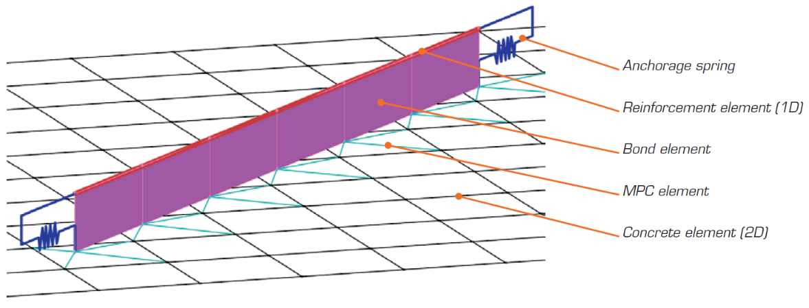
Fig. 7 Example of finite element model representation in IDEA StatiCa Detail
(Fig. 7) The FEM model in CSFM is composed of several types of finite elements:
- 1-D element with axial stiffness for reinforcement
- 2-D isoparametric element for concrete
- End springs for the reinforcement anchorage model with end treatment
- Special 2-D element to model cohesion between reinforcement and concrete
- Rigid and interpolating constraints (Multi-Point Constraints, MPC) between cohesion elements and concrete
If the designed reinforcement prevents brittle failure of the element, the CSFM has been shown to give very good predictions of the response and ultimate capacity of the structure despite the simplicity of the formulation. In other words, the method is not suitable, for example, for the design of beams without transverse shear reinforcement that exhibits potentially brittle behavior. Verifications of the method, including experiments, are given in [1]. A more detailed description of the method is beyond the scope of the paper and can also be found in Theoretical Background.
It is clear that the principles of CSFM are general and thus, its application is not limited to D-regions, but can be used to model whole members e.g. precast girders, and where the element can be simplified to a planar 2D model. The method and its implementation in software (IDEA StatiCa Detail) have also been extended, with the possibility of specifying pre-stressed and post-tensioned reinforcement.
3. Example of pier cap design
The practical application of CSFM is shown in the design of the bridge pier cap in Figure 8. This is the second pier of a continuous bridge with three spans of 30.0 m, 42.0 m, and 30.0 m. The head of the reinforced concrete pier is designed in C40/50 concrete and its thickness (in the longitudinal direction of the bridge) is 2.0 m.
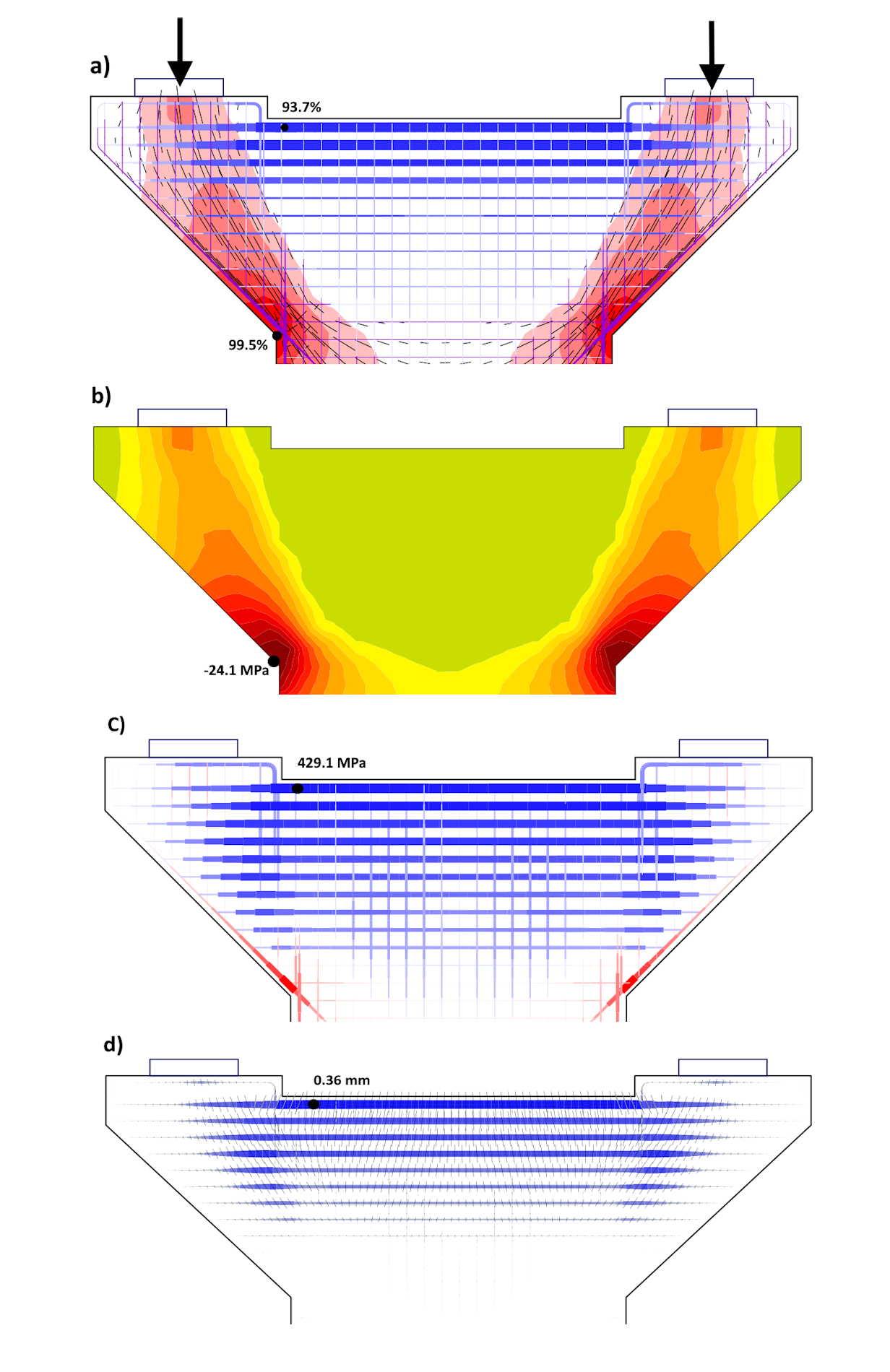
Fig. 8 Pier cap: a) Summary design; b) Compression stress in concrete in ULS; c) Tension stress in reinforcement in ULS; d) Crack width in SLS
At the top of the pier cap, a transverse beam of B500 reinforcement 20xϕ28+20xϕ25 - the top four layers - was first designed. Figure 8a shows a summary design at the ultimate limit state, showing the compressive stresses in the concrete, the directions of the compressive stresses, and the stresses in the reinforcement. More detailed stress distribution in the concrete and reinforcement are then documented in Figures 8b and 8c. The transversal reinforcement is just below the yield strength also the stresses in the concrete (and the relative strains) are satisfactory at ULS. However, the result of the crack width calculation (Fig. 8d) shows that the design does not satisfy in SLS: wmax = 0.36 mm > wlim = 0.3 mm. To meet the limiting crack width, it is necessary to increase the reinforcement of the cross member to 20xϕ32+20xϕ28. In the case of wlim = 0.2 mm (e.g. pier near a road generating salt spray, environmental influence level XF2), the reinforcement of the cross member would have to be increased even to 24xϕ32+24xϕ28.
Conclusion
CSFM suits engineering practice because it uses simple material models defined in a design standard. In addition to the ultimate limit states, it also allows the design of serviceability limit states. For which the assessment was previously difficult to imagine when using S&T models. By implementing the method in IDEA StatiCa Detail, it is then possible to realistically capture the structure's response and to design and assess discontinuity regions and larger assemblies efficiently and safely.
The CSFM was developed mainly through the work of Professor Walter Kaufmann, Head of the Chair of Structural Engineering, Swiss Federal Institute of Technology (ETH) Zurich. He and his team also verified the method and its software implementation.
Literature
[1] KAUFMANN, Walter, et al.: Compatible stress field design of structural concrete, ETH Zurich, 2020, ISBN 978-3-906916-95-8,
[2] KAUFMANN, W., MARTI, P.: Structural Concrete: Cracked Membrane Model. Journal of Structural Engineering 124 (12): 1467-75, 1998 https://doi.org/10.1061/(ASCE)0733-9445(1998)124:12(1467)
[3] KRAUS, M., M. WEBER, W. KAUFMANN, W, BOBEK, L.: Numerical analysis of experimentally tested frame corners with opening moments using the Compatible Stress Field Method (CSFM). In: Computational Modelling of Concrete and Concrete Structures, pp. 694-03. CRC Press, 2022 https://doi.org/10.1201/9781003316404
Author
Ing. Pavel Kaláb, Ph.D.
IDEA StatiCa s.r.o.