Diseño estructural de un cabezal de pilares desde DXF (EN)
1 Nuevo proyecto
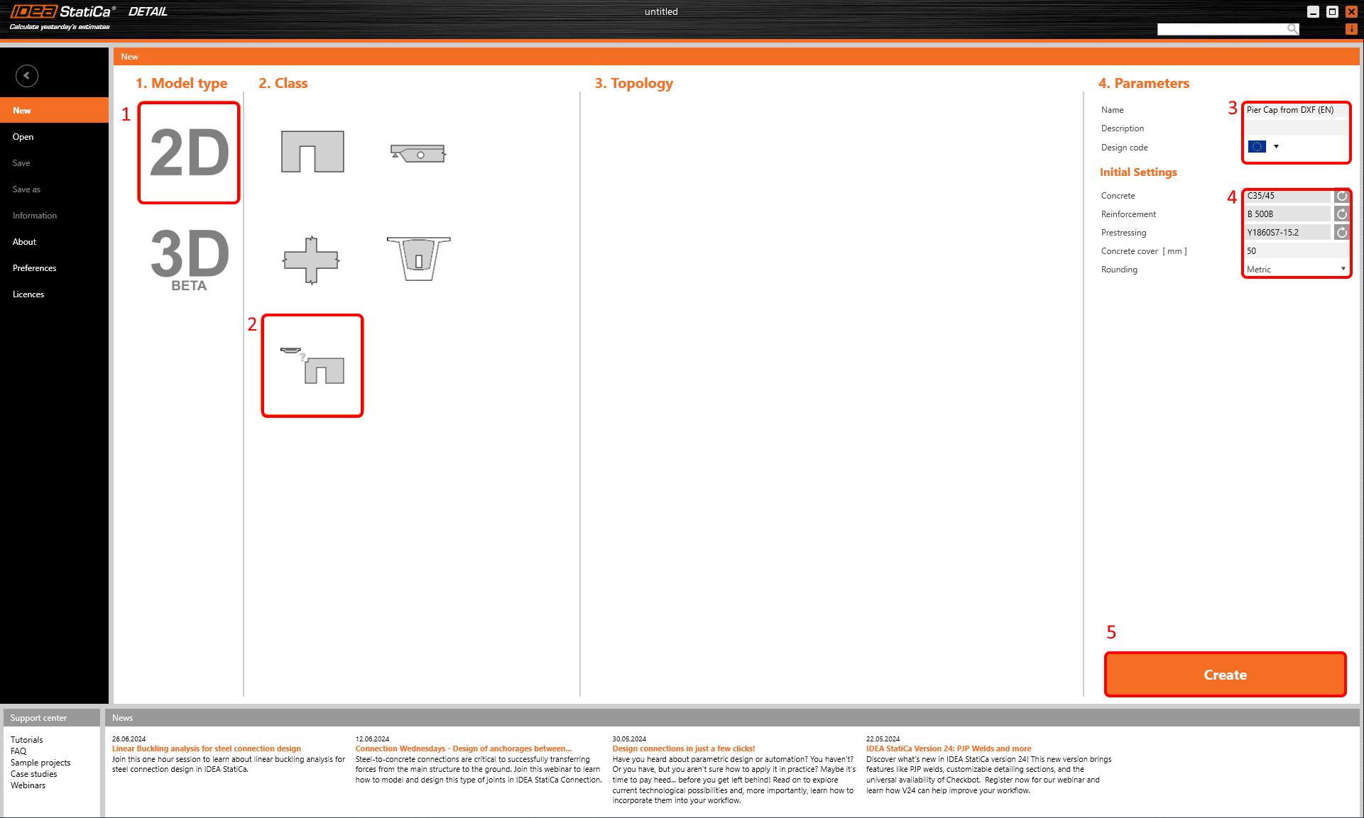
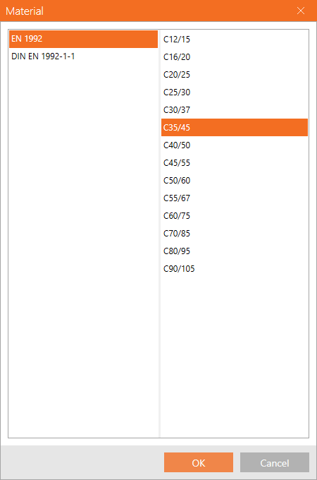
Iniciemos IDEA StatiCa (descargue la versión más reciente) y seleccione la aplicación Detail. Configure un nuevo proyecto haciendo clic en 2D Detail con la sección de entrada general, seleccione el grado de hormigón y el recubrimiento adecuados. Finalice la configuración haciendo clic en Crear.
Esto cargará un proyecto en blanco donde comenzaremos desde cero.
2 Geometría
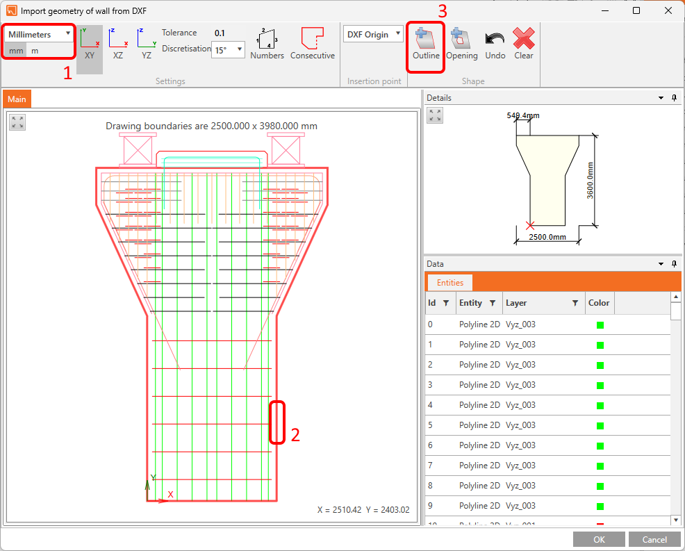
Comience con la adición de un elemento de muro mediante el botón Importar DXF.
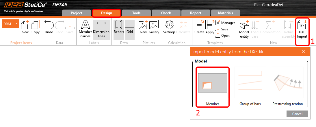
Aparecerá un cuadro de diálogo para localizar y abrir el archivo DXF deseado. Tras seleccionar pier_cap.dxf (disponible en los archivos fuente), accederá a un cuadro de diálogo de selección. Seleccione la parte del contorno del cabezal de pilares (si utilizó líneas en DXF, continúe con el botón Consecutivo) y haga clic en Contorno. Finalice la selección con el botón Aceptar.
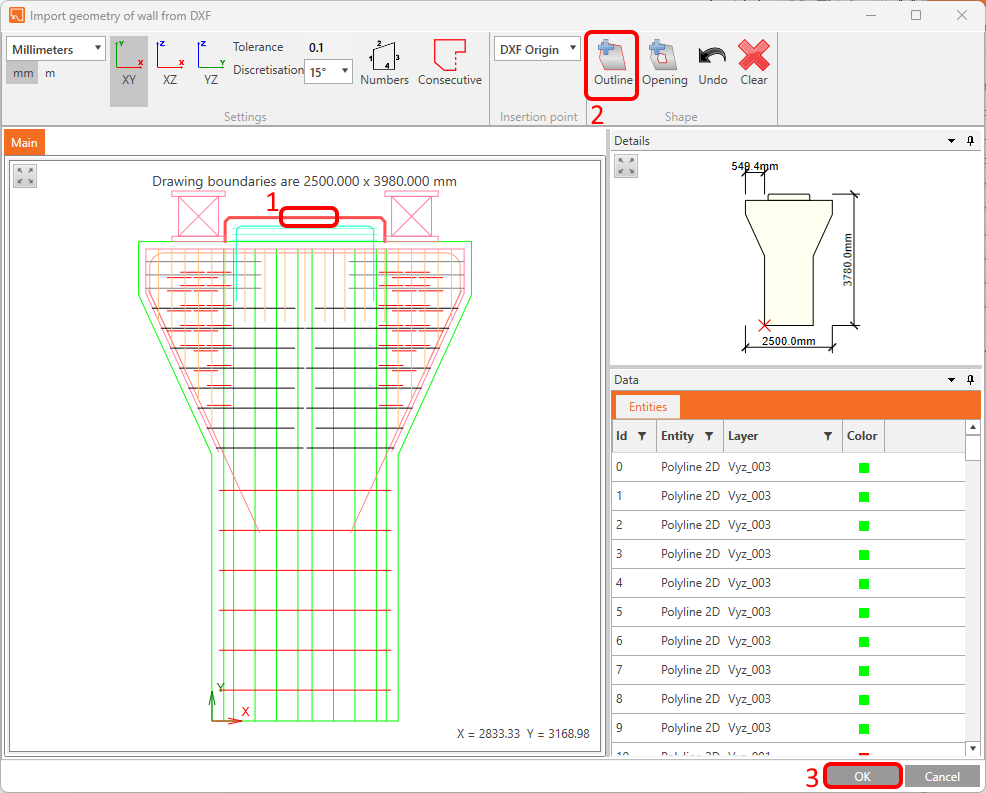
A continuación, importe la parte superior del cabezal de pilares desde el mismo archivo DXF.
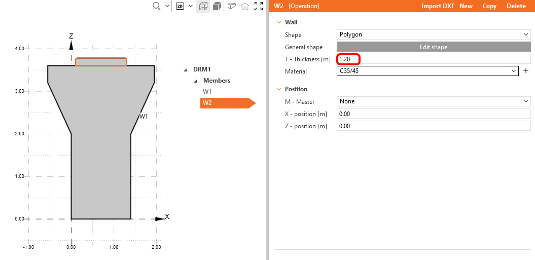
Las formas de los elementos de muro han sido generadas por DXF, pero la referencia DXF 2D carece de información sobre el espesor, por lo que debe ajustarlo manualmente ahora. Establezca el Espesor para los elementos W1 y W2 en 1,20 m.
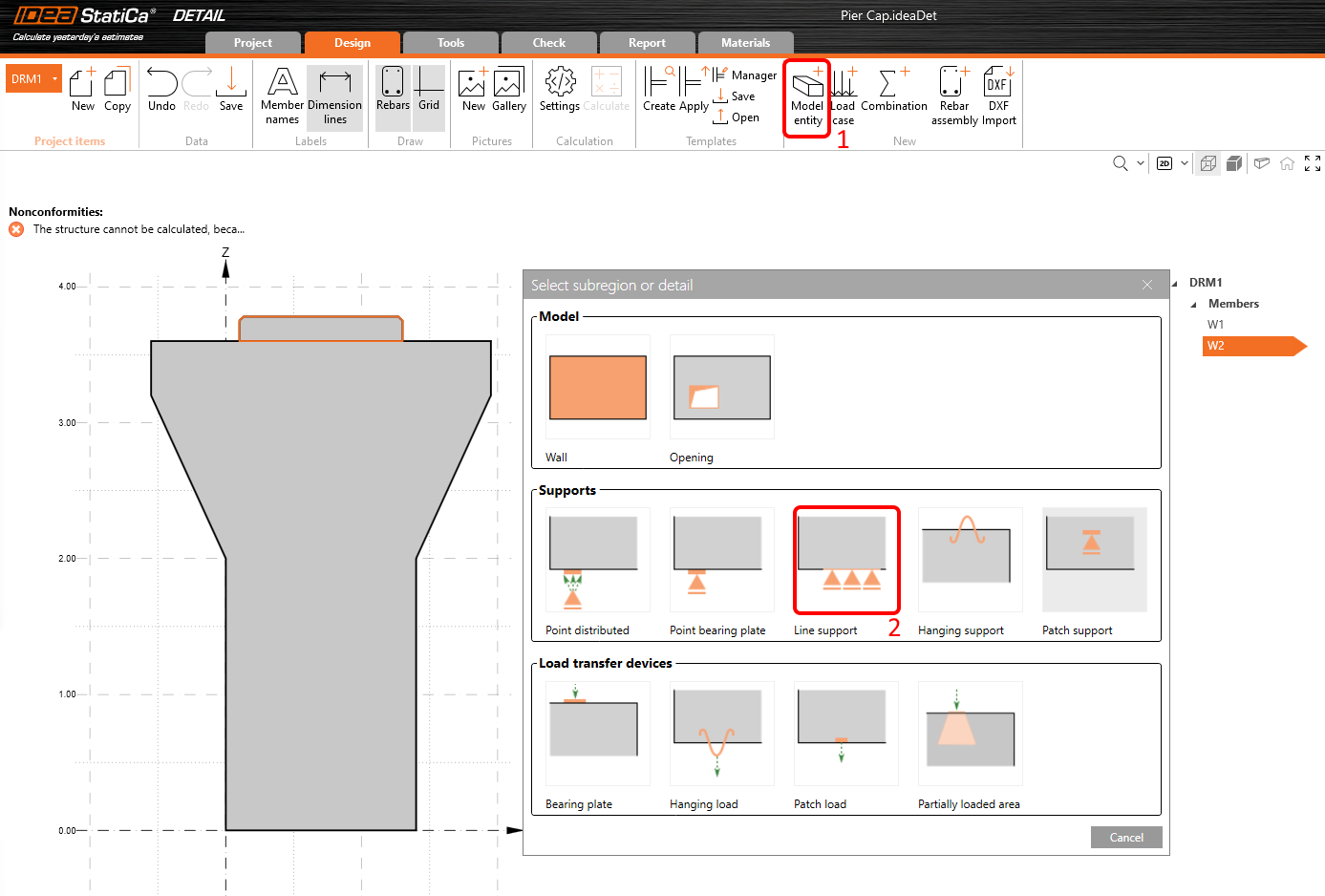
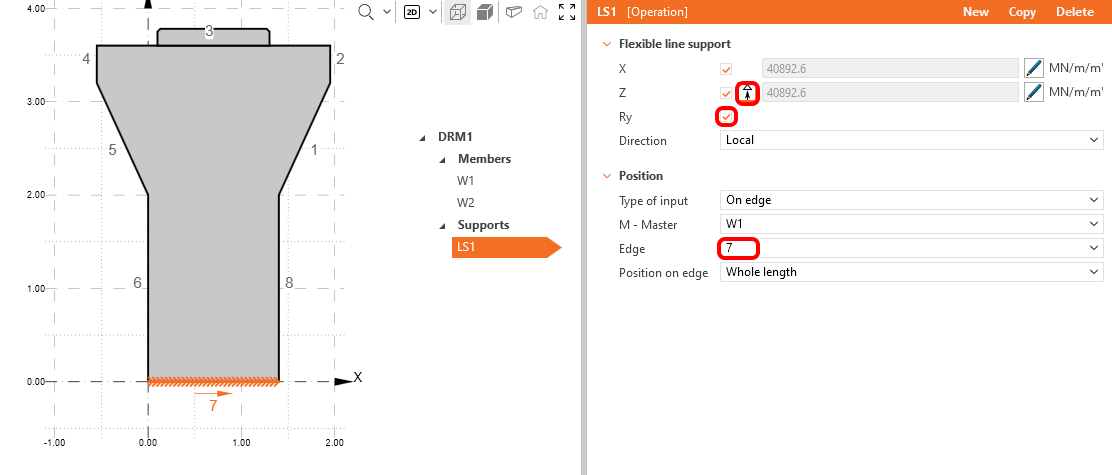
En este momento, nuestra estructura está estáticamente sobredeterminada, por lo que es necesario añadir condiciones de contorno. Para crear un apoyo lineal, haga clic en el botón Entidad de modelo y seleccione el tercer tipo en la sección Apoyos.
Restrinja el apoyo en las direcciones X, Z y Ry y cambie el número de borde a 7. Además, desactive la funcionalidad Solo compresión. Los números de borde pueden verse en la Ventana principal.
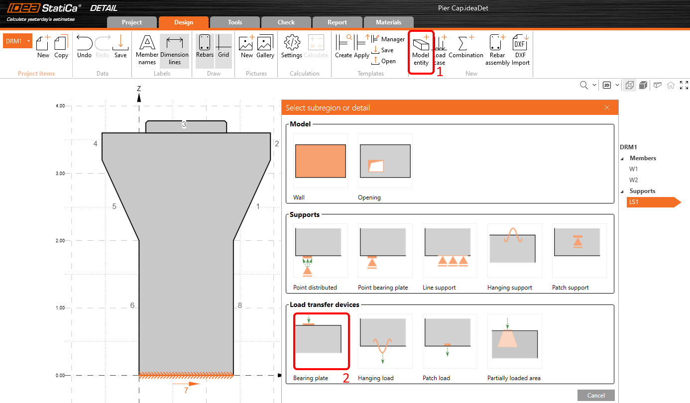
Como una fuerza puntual colocada directamente sobre el borde de un cabezal de pilares podría provocar un fallo local del hormigón a compresión, utilizaremos placas de apoyo para distribuir la carga de manera más uniforme. Para añadir una, pulse el botón Entidad de modelo de nuevo, y en la sección Dispositivos de transferencia de carga, seleccione el primero - Placa de apoyo.
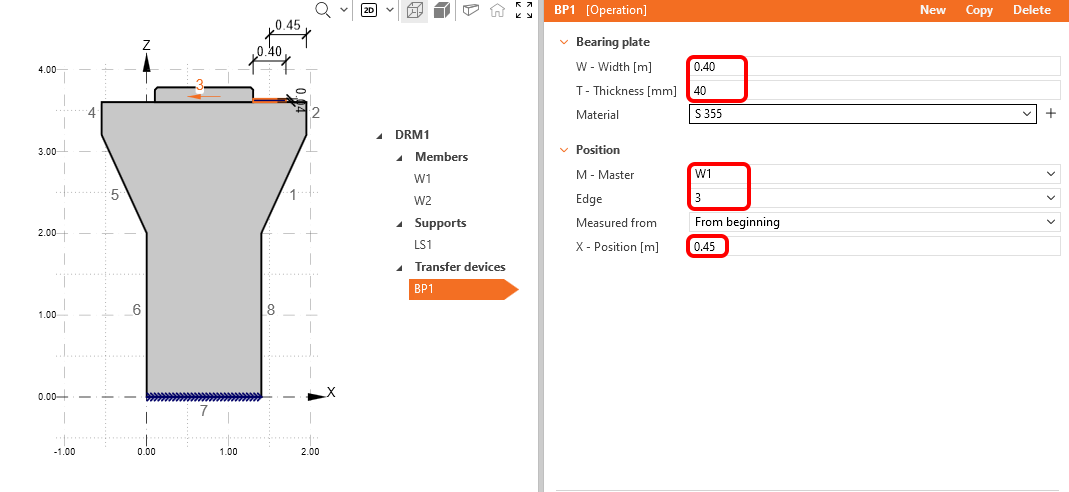
Cambie el Ancho a 0,40 m y el Espesor a 0,04 m, luego el número de Borde a 3 y desplace su Posición X a 0,45 m.
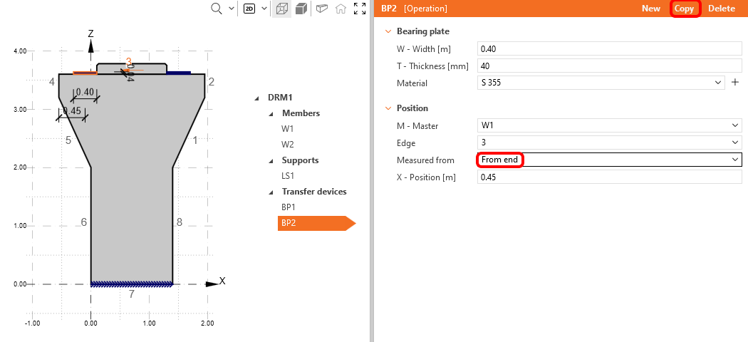
A continuación, copie la Placa de apoyo y cambie su posición para que se mida Desde el extremo.
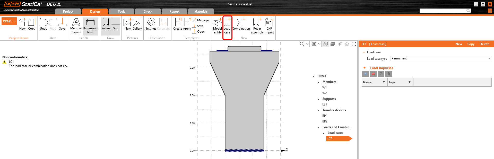
3 Cargas
El caso de carga se creará haciendo clic en el botón Caso de carga y es para efectos Permanentes por defecto. Necesita dos casos de carga para distinguir entre cargas permanentes y variables, y tres combinaciones para cubrir un estado límite ELU y dos combinaciones ELS (Característica y Cuasi-permanente) para todas las verificaciones.
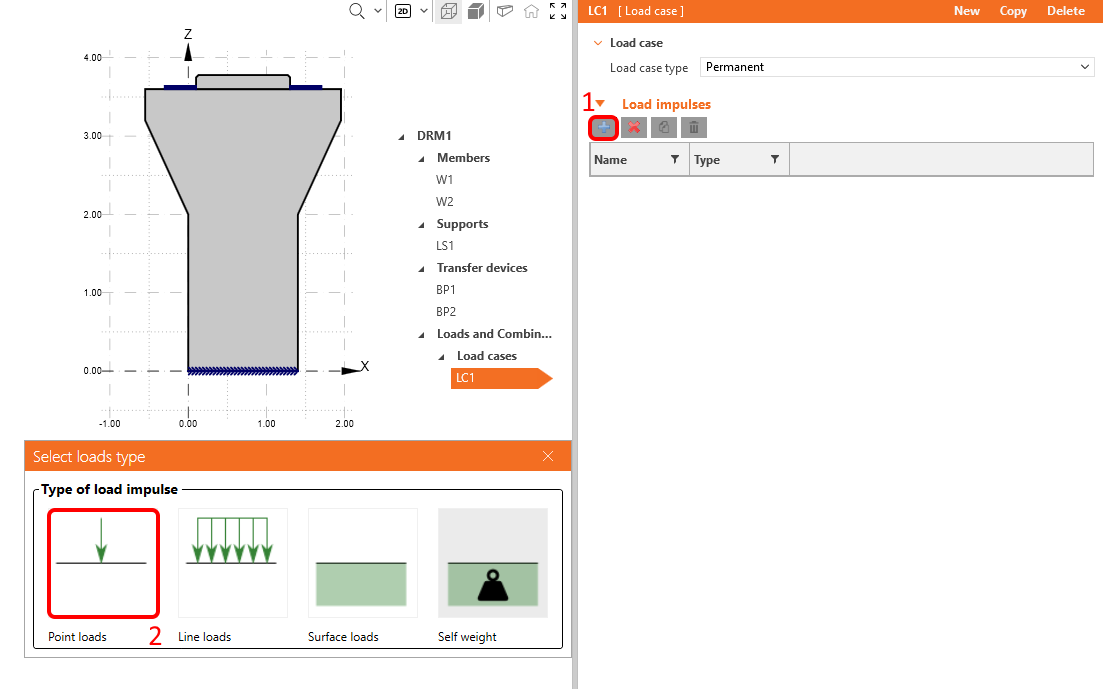
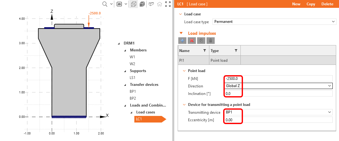
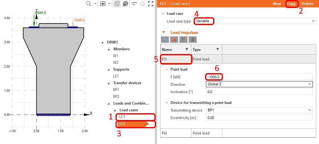
Modifiquemos el caso de carga añadido automáticamente LC1 para efectos permanentes. En la pestaña Impulsos de carga, haga clic en el botón Más y aplique una Carga puntual. Se colocará automáticamente en una de las placas de apoyo.
Como último paso, cambie su valor a -2500 kN.
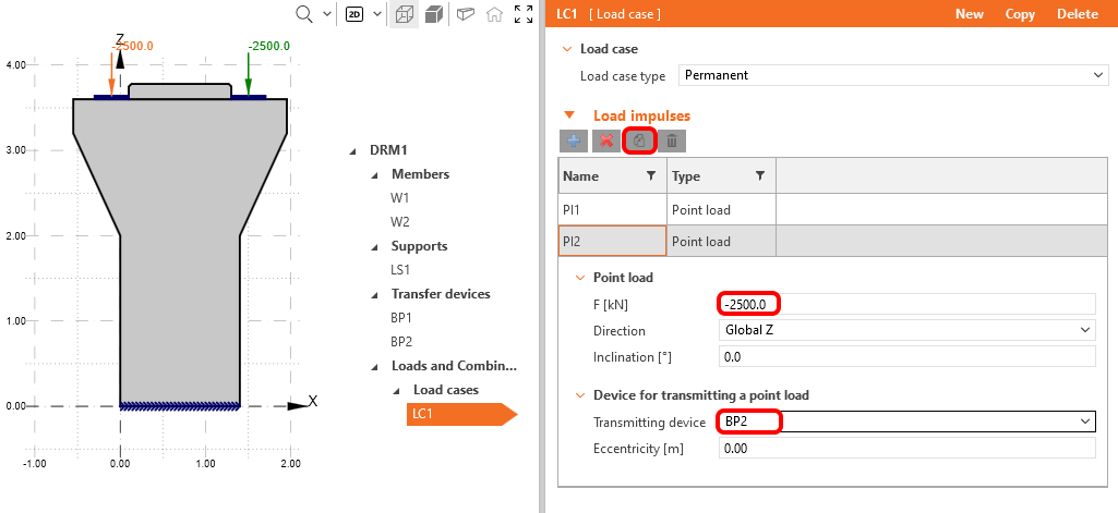
Copie esa carga puntual a la otra placa de apoyo BP2.
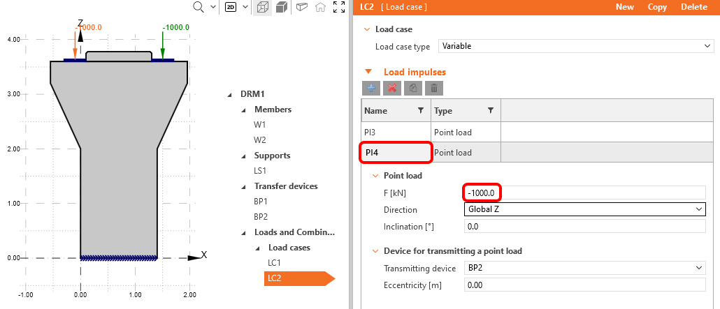
Copie el Caso de Carga 1 y cambie el tipo de LC a variable. Haga clic en Carga puntual y cambie la fuerza a -1000 kN.
Repita los pasos para la última carga puntual.
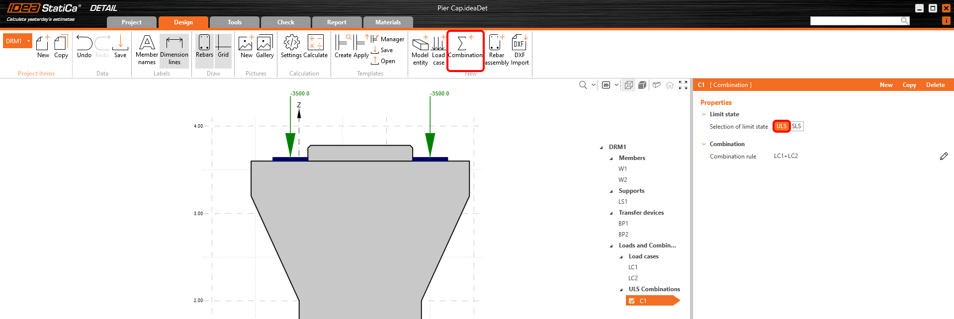
Cree la primera combinación no lineal mediante el botón Combinación y configúrela como estado límite ELU.
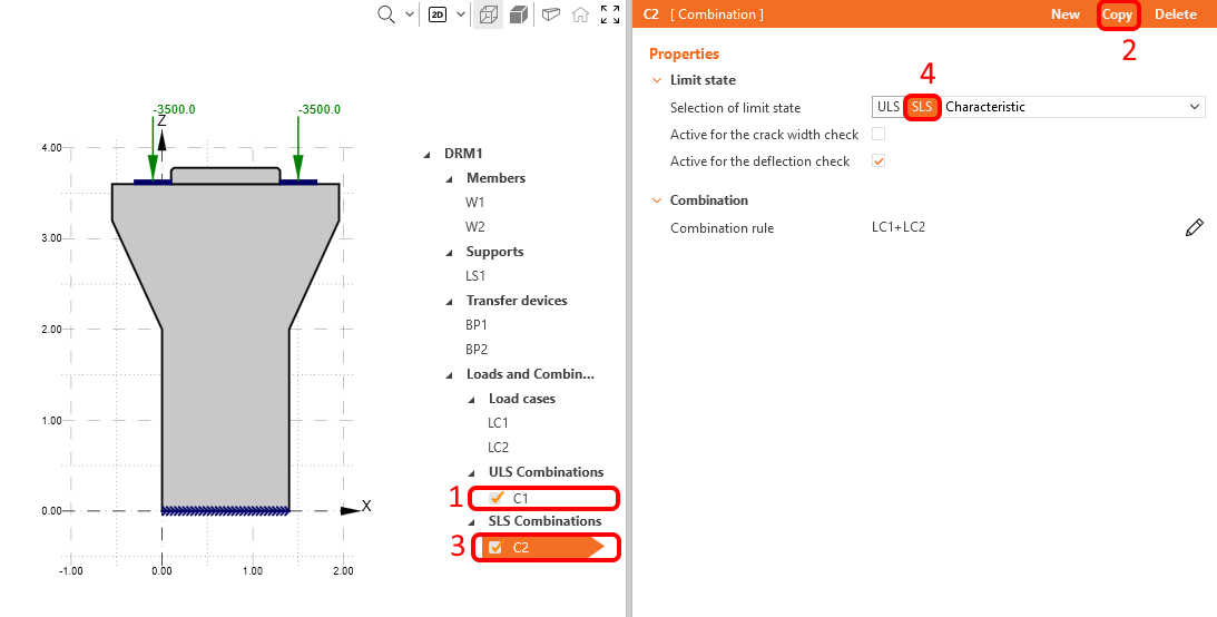
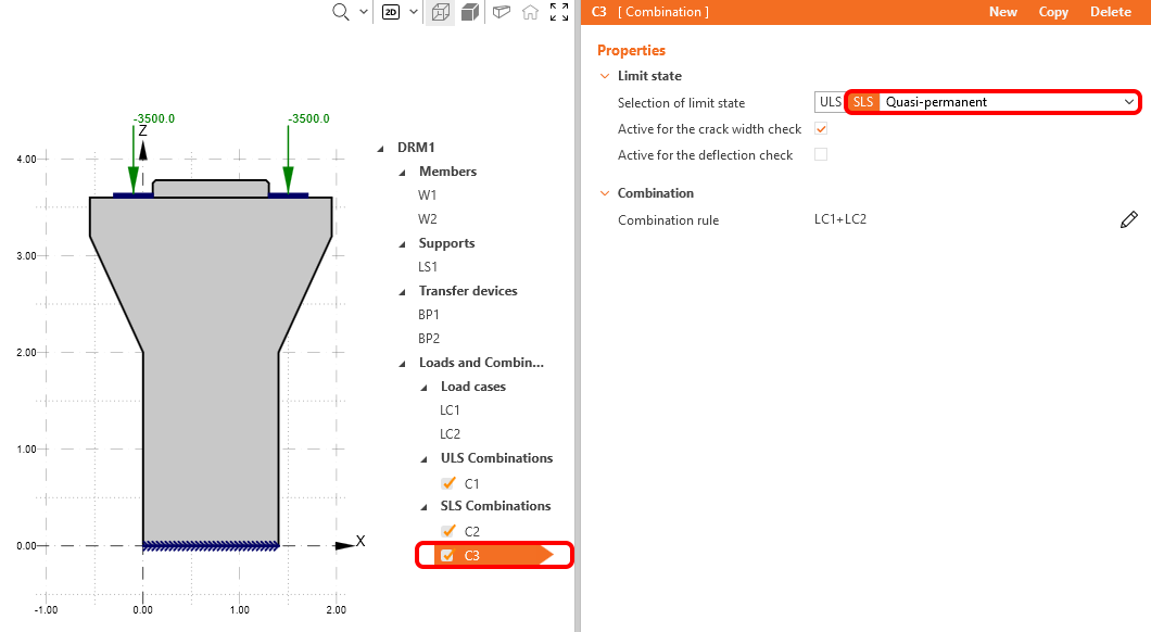
Copie C1 y elija ELS Característica. Además, está disponible la opción de verificar la combinación en cuanto a flecha y ancho de fisura, tanto para una combinación dada como individualmente. Para la combinación Característica, elija Activo para la verificación de flecha según la imagen siguiente.
Ahora puede repetir los pasos, copiar C2 y elegir ELS Cuasi-Permanente para la nueva C3. Active la combinación Cuasi-Permanente solo para el cálculo del ancho de fisura.
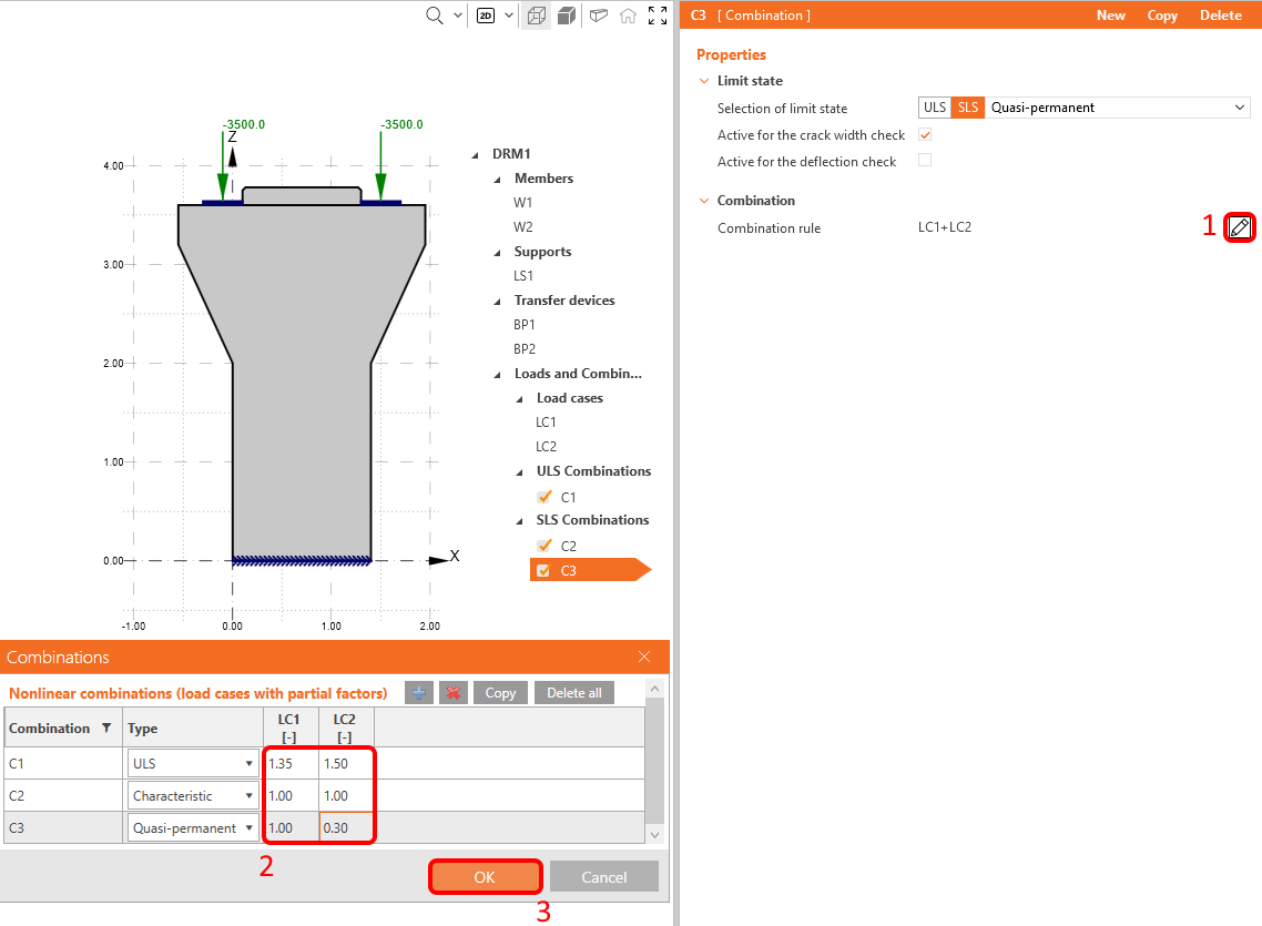
Ahora, cambie los coeficientes parciales para todas las combinaciones. Para ello, haga clic en el icono de lápiz en cualquier combinación que haya definido y cambie los coeficientes parciales que se muestran en la siguiente imagen.
Tenga en cuenta que los cálculos se realizan únicamente para las combinaciones de casos de carga que están marcadas en el árbol de operaciones, no para los casos de carga individuales.
4 Armadura
El siguiente paso es armar el modelo. Combine la definición desde cero en IDEA StatiCa con la importación masiva de la armadura desde el archivo DXF. En este tutorial, asumimos que el usuario sabe cómo armar un cabezal de pilares y ha preparado con antelación cierta armadura en DXF a partir de planos; por lo tanto, dejamos las herramientas para el diseño de armadura para otro tutorial.
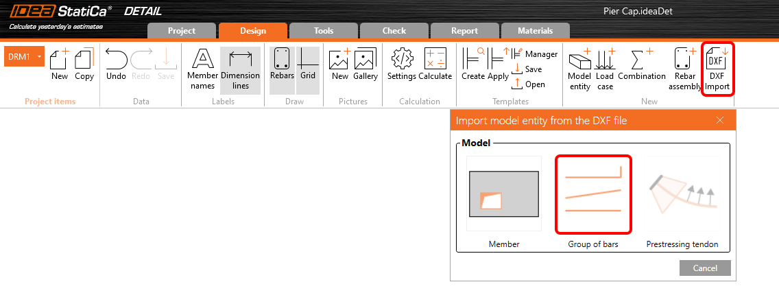
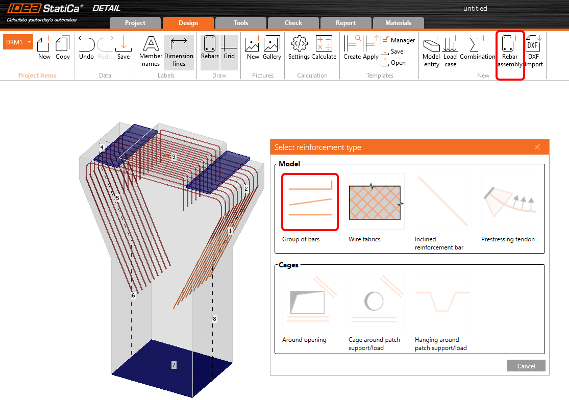
Haga clic en Importar DXF y elija la entidad Grupo de barras.
Aparecerá un cuadro de diálogo para localizar y abrir el archivo DXF deseado. Tras seleccionar pier_cap.dxf (disponible en los archivos fuente), accederá a un cuadro de diálogo de selección. Seleccione todas las polilíneas (forma de las barras) que necesite en el orden mostrado en la siguiente imagen y haga clic en Seleccionar después de cada polilínea (el orden no es importante en general, simplemente queremos hacer un seguimiento en este tutorial cuando hablamos del nombre específico de un elemento). Finalice la selección con el botón Aceptar.

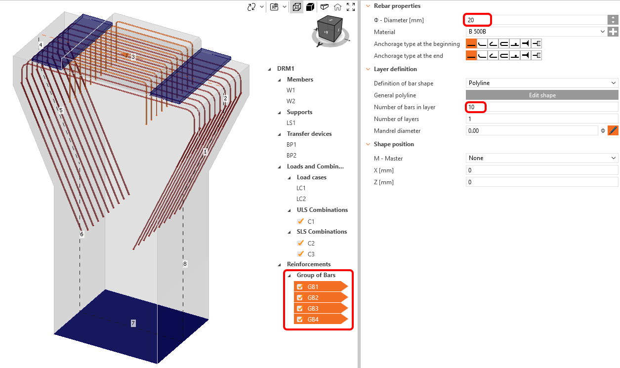
El archivo DXF 2D transfiere el ancho global de una polilínea como el diámetro de cada barra de armadura, pero no contiene información sobre el número de barras en la dirección perpendicular, por lo que debemos ajustarlas manualmente. Gracias a la función de edición múltiple, podemos realizar todos los cambios para todas las entidades de armadura a la vez.
Mantenga presionado Ctrl y seleccione toda la armadura importada, cambie el número de barras en una capa a 10 y el diámetro a 20 mm.
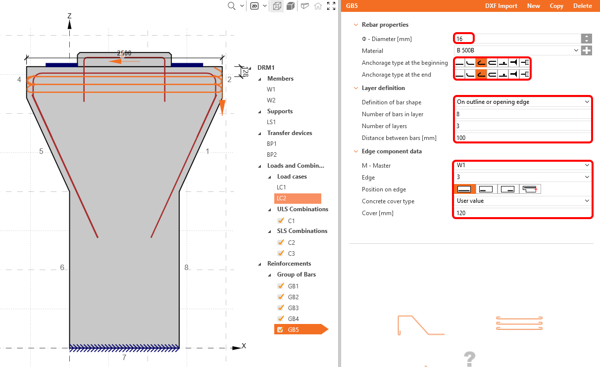
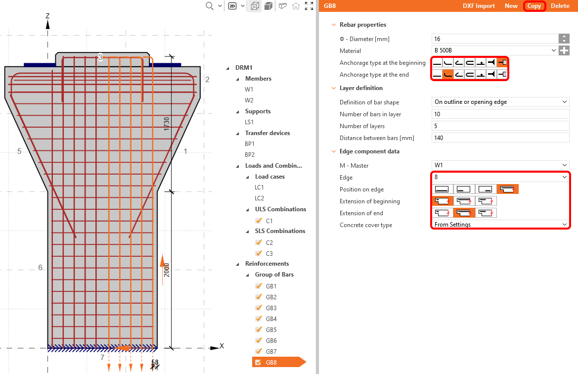
Para completar la armadura en este ejemplo, combine la referencia del DXF con la armadura definida en IDEA StatiCa Detail. En este caso, añada algo de armadura horizontal y longitudinal al cabezal de pilares y algunas capas de armadura que representen los estribos en el pilar. Haga clic en el botón Conjunto de barras y seleccione el primer elemento de armadura Grupo de barras.
Cambie la definición a En borde de contorno o apertura. A continuación, ajuste el número de capas, sus distancias, el diámetro, el número de barras en una capa, el tipo de anclaje para ambos extremos y bordes según la siguiente imagen:
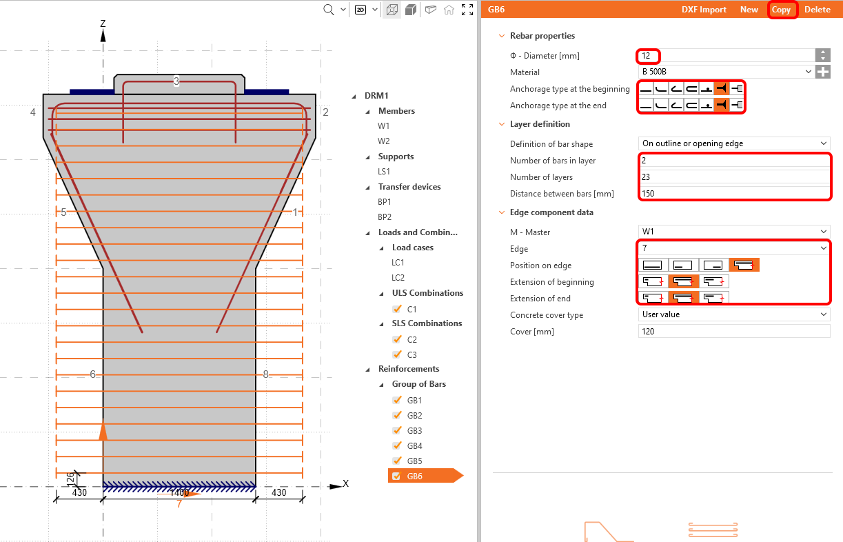
Use la función copiar para crear GB6, que representará los estribos, y cambie el borde a 7. Establezca todos los parámetros según la imagen siguiente:
Los últimos elementos de armadura introducirán la armadura longitudinal del cabezal de pilares. Para ello, añada un nuevo grupo de barras. Cambie las propiedades de la siguiente manera:
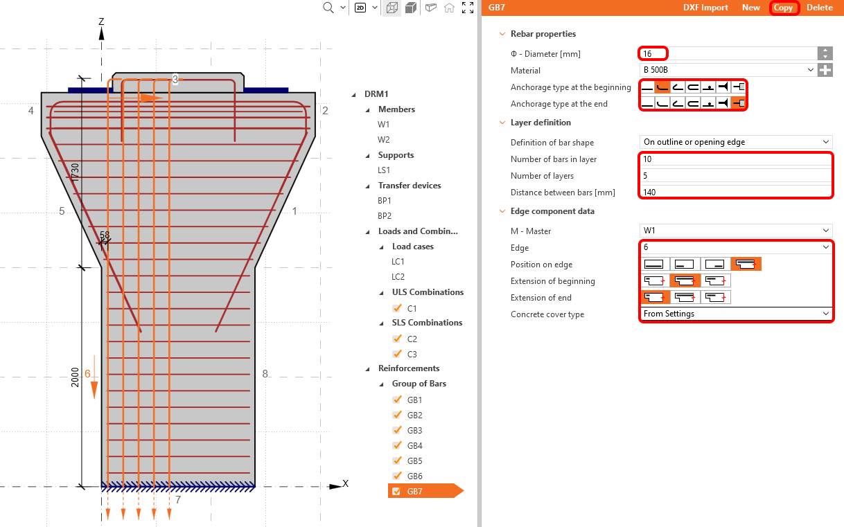
Use el botón copiar por última vez. Cambie el borde a 8.
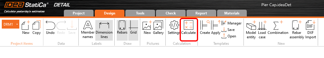
Una vez añadida y editada toda la armadura, podemos iniciar el cálculo haciendo clic en el botón Calcular.
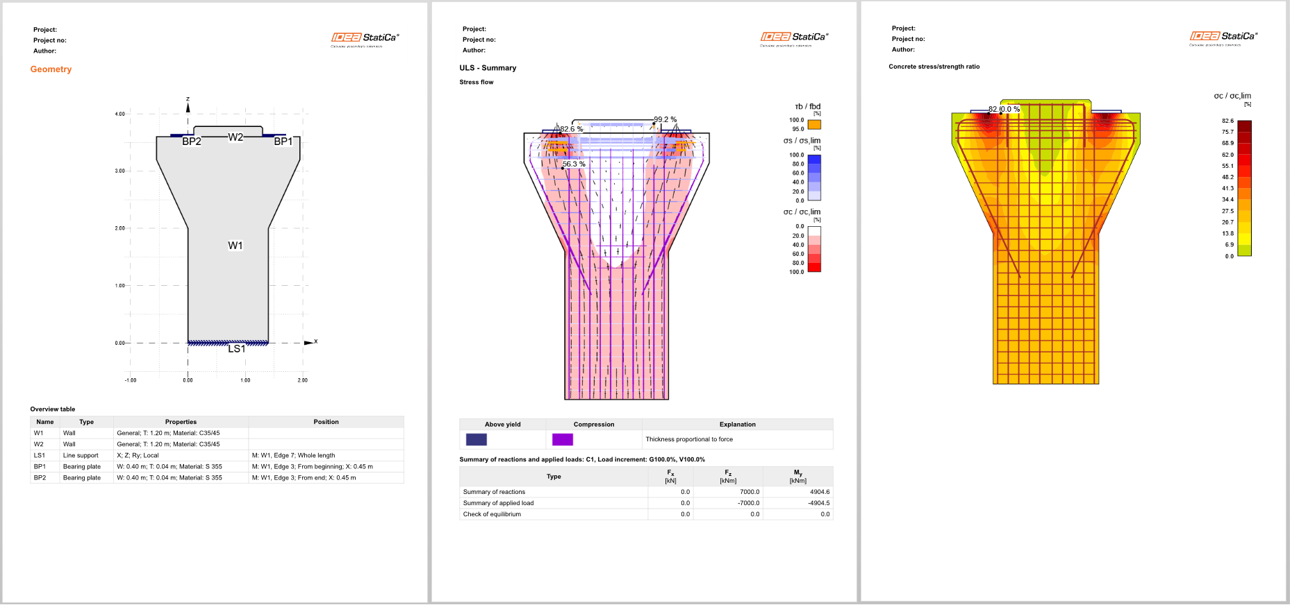
5 Cálculo y verificación
Inicie el análisis haciendo clic en Cálculo en la cinta de opciones. El modelo de análisis se genera automáticamente, se realizan los cálculos y puede ver el resumen de las verificaciones mostrado junto con los valores de los resultados de verificación.
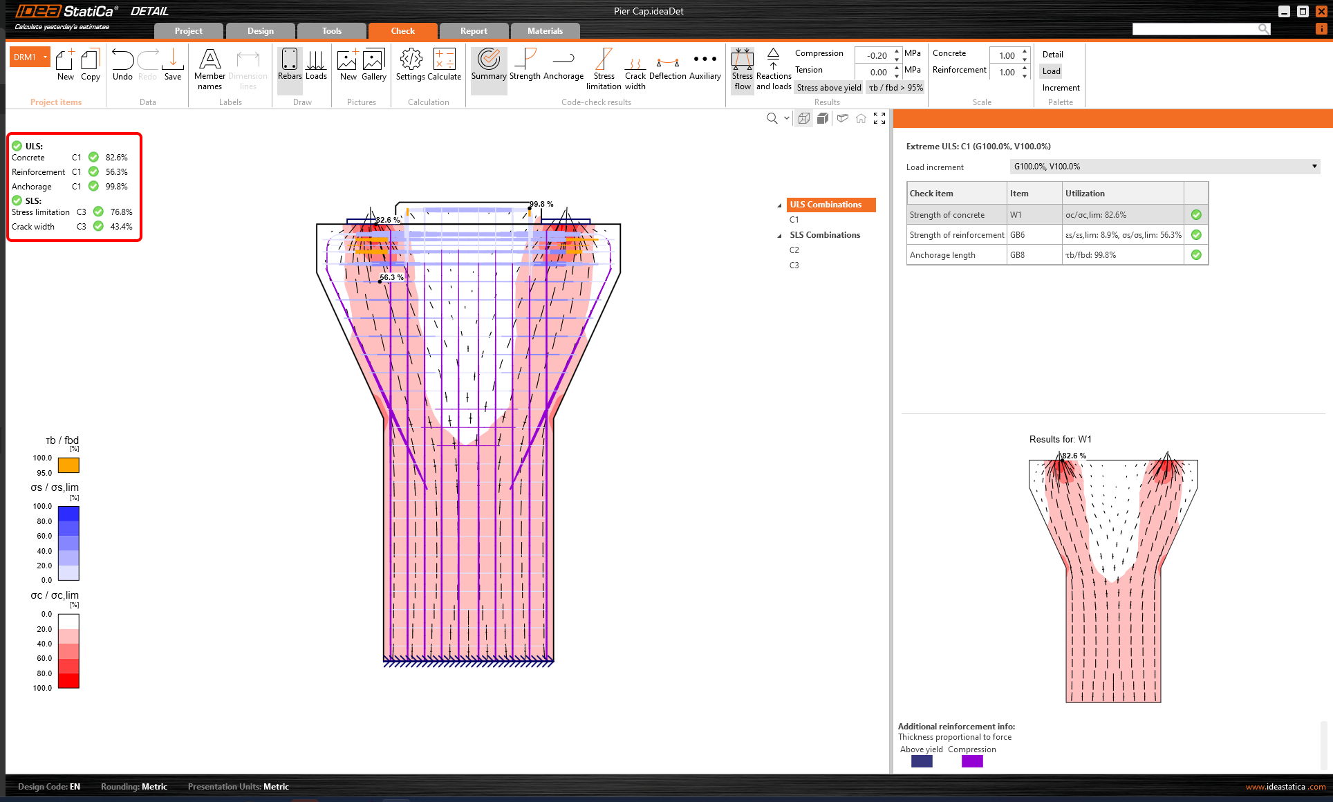
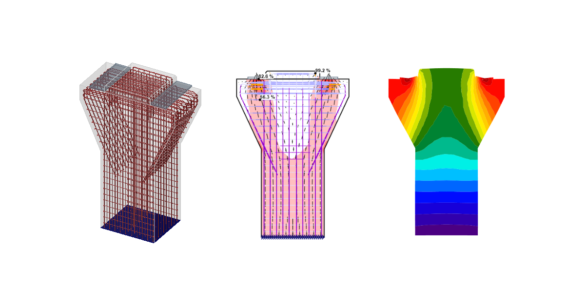
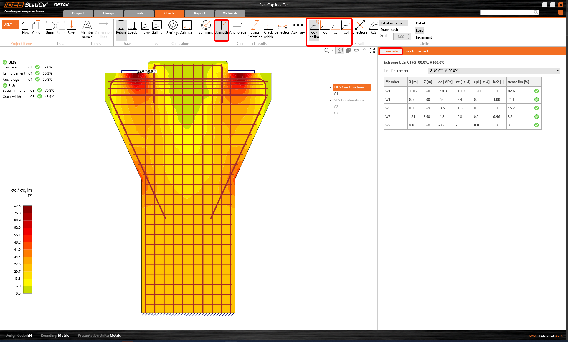
Para revisar las verificaciones detalladas de cada componente, comience con la pestaña Resistencia. Esto mostrará las verificaciones del hormigón, como la utilización en tensión, las tensiones principales, las deformaciones y un mapa del factor de reducción kc, que puede activarse en la cinta de opciones.
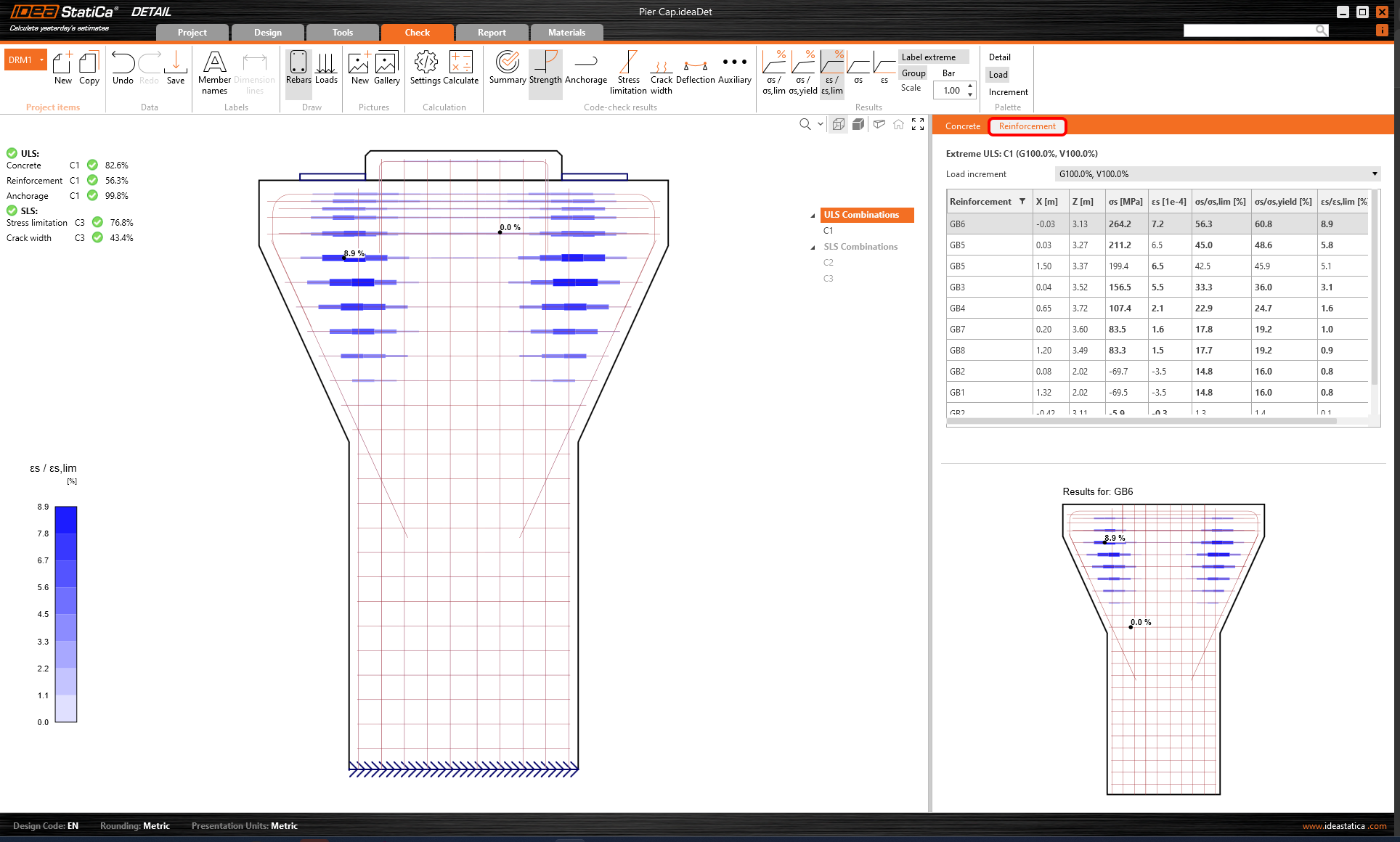
Para obtener resultados detallados de la armadura, debe hacer clic en la fila Armadura. Esto cambiará los iconos de la cinta de opciones y desplegará la tabla de resultados. Puede mostrar los resultados de deformaciones y tensiones en cada barra y su utilización.
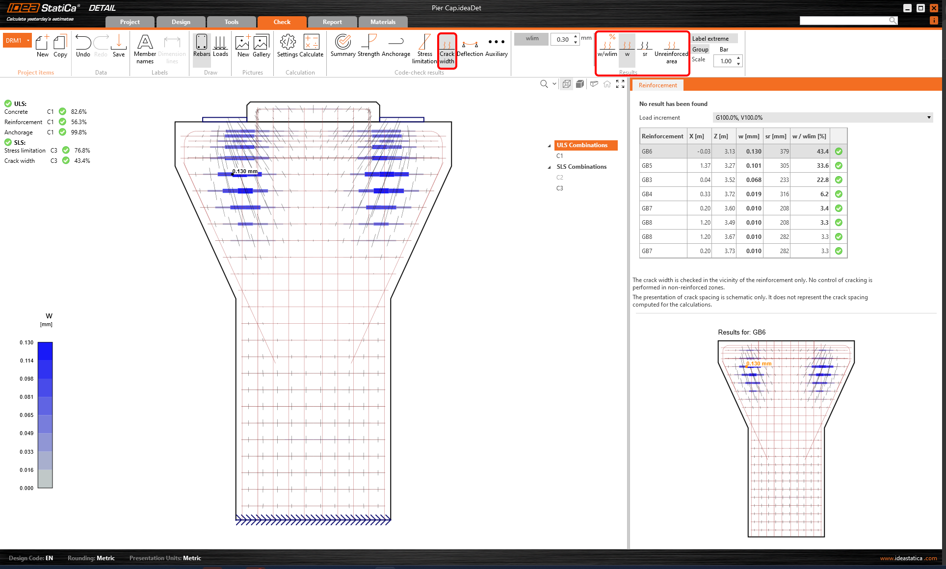
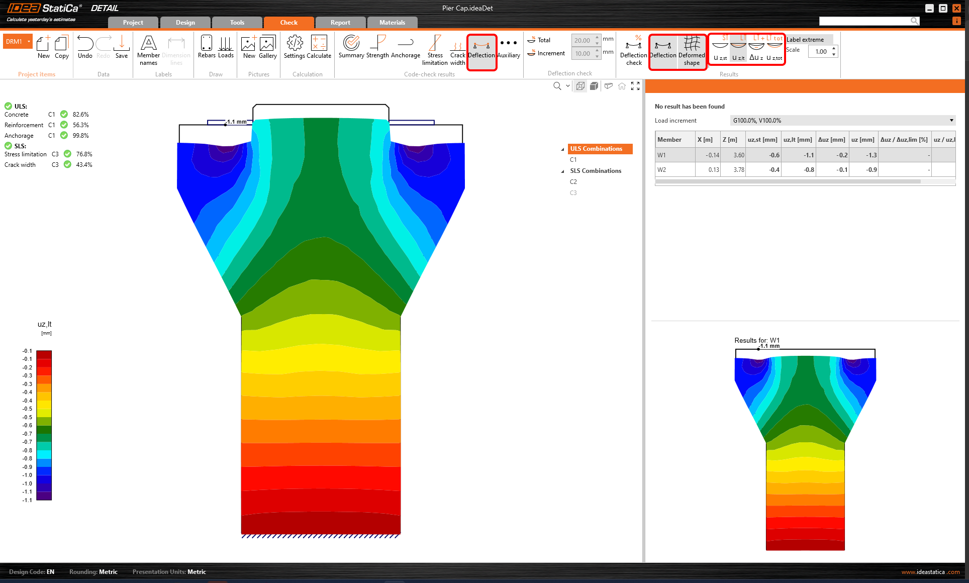
Todos los resultados pueden mostrarse de la misma manera. Mostremos la diferencia en la cinta de opciones para las verificaciones ELS de ancho de fisura y flecha. Además de los iconos para cambiar entre los resultados, hay configuraciones en la cinta de opciones para establecer el valor límite de las fisuras o para mostrar los resultados de las flechas de los modelos a corto/largo plazo.
6 Informe
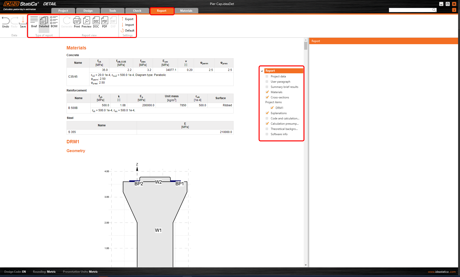
Por último, vaya al Informe. IDEA StatiCa ofrece un informe totalmente personalizable para imprimir o guardar en un formato editable.
Ha diseñado, optimizado y realizado la verificación normativa de un cabezal de pilares según el Eurocódigo.