Introduction
The objective of this comparison is to prove that the results provided by IDEA StatiCa are similar or safe compared to 3rd party general finite element software. ANSYS software [1], which is considered proven and reliable, was selected. The ANSYS model was created and evaluated by prof. Ing. Jiří Kala, Ph.D. at Brno University of Technology, Czech Republic.
Two selected joints were selected and modeled in ANSYS, release 19.2, and IDEA StatiCa Connection, release 21.1.4.
ANSYS model
There are multiple ways how to model steel connections. The goal was to verify that the finite elements used in IDEA StatiCa model work as intended. Therefore, the model in ANSYS was created with the intention to mimic the automatically created model in IDEA StatiCa. While this is fairly easy for plates, it is very complicated for welds and bolts, because they contain special finite elements that simulate the resistance and load-deformation properties of bolts and welds according to the codes, such as Code of Practice for the Structural Use of Steel 2011 [2]. They are also connected to the plates by a sophisticated assembly of multipoint constraints and other complementary elements.
ANSYS model was created using shell elements SHELL 181 in their centreline. SHELL 181 is a 4-node isoparametric shell element with six degrees of freedom in each node. Five integration layers along the shell thickness were used. Plates, welds, as well as bolt heads and nuts were simulated by this element with von Mises yield criterion. The yield strengths of plates were 275 MPa for steel plates with a thickness below or equal to 16 mm and 265 MPa for plates with a thickness above 16 mm.
Simulation of welded connections is a difficult task. A combined model of weld prepared by Turlier [3] was used. It consists of an inclined shell element simulating the weld. Its thickness and width are equal to the throat thickness. Further, it contains shell elements with elastic material model connecting the inclined shell element to the mesh of the shell elements simulating plates through the plate thickness. Von Mises yield criterion is typically checked for the inclined shell element of the weld. It is not ideal for the comparison because the design weld model is simplified and some stresses in the weld are not assumed.
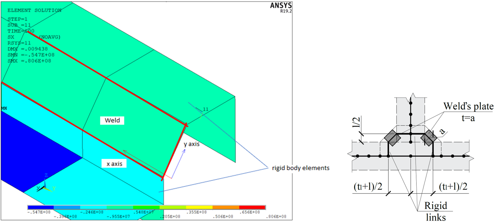
Figure 1: Combined model of weld
A contact is described by a couple of elements CONTA 174 and TARGE 170 between the surface of end plate and column flange and also between the bolt head (nut) and plates. A contact algorithm Augmented Lagrange method and contact searching in places of Gauss points was used. Friction coefficient 0.3 was used. The difference between frictionless contact is small. Because no bolt preload is assumed, the end plate initially, at small load increments, moves downward and is restrained by bolts when the contact stress is still very low. Surface-surface variant of the flexible contact was used.
Bolt was modeled by BEAM 188 element with elastic material and corresponding area. The bolt is fixed on both ends in the shell elements simulating a bolt head and a nut. Additional elements ensured the position of bolt in the bolt holes in plates.
Several variants were created with different contact settings. A Contact is in its nature a geometrically nonlinear feature. A solution was found for an analysis with large deformations, where the equations of equilibriums are updated on a deformed model; however, a solution was found also for analysis with small deformations. Contacts with friction coefficients 0.3 and 0.0 were tried. These variants served to quantify and minimize the risk of inaccuracies of the numerical analysis. Above mentioned variants provided coherent and similar results. Detailed assessment was done just with one model that is reliable and corresponds to the methods of compared IDEA StatiCa model.
Sparse matrix direct solver was used for the analysis. Nonlinear analysis uses full Newton-Raphson method. Automatic selection of load steps was used. The initial load corresponds to 0.01 of the applied load, minimal and maximal load increment is 0.002 and 1, respectively. Maximum number of iterations in each step is 22.
Example 1
Example 1 is a beam-to-column joint. The beam cross-section is UB 686 x 254 x 125. The column cross-section is UC 356 x 406 x 235 and is fixed at both ends. Steel grade S275 is used for all members and plates. The connection is designed as end plate with eight bolts M45 grade 10.9. The factored load at the beam in the joint is calculated:
- My = 920 kNm
- Vz = 460 kN
ANSYS model
The ANSYS model has a column with a length of 5 216 mm, which corresponds to IDEA StatiCa model. The column is fixed at both ends. The beam is modeled as a cantilever with a length of 2 000 mm (node to end) and loaded by the downward force of 460 kN, which was equally distributed among the nodes simulating the beam web. Unlike IDEA StatiCa model, the column and the beam are created by shell elements along the whole length. In IDEA StatiCa, only the joint is created by shell elements. For the rest of the members, the condensed elements are used.
43 076 SHELL 181 elements were used to create the model. The analysis model had 259 326 equations with a width of 144. 12 substeps and 31 iterations were needed to finish the analysis.
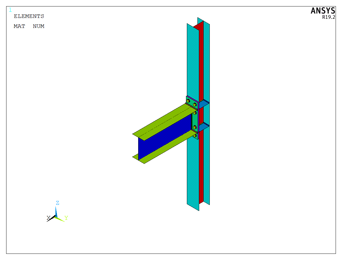
Figure 2: ANSYS shell model – the overall picture
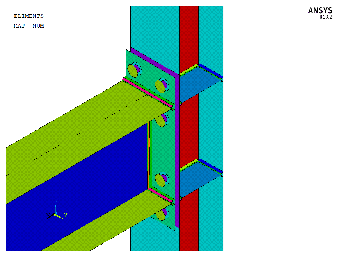
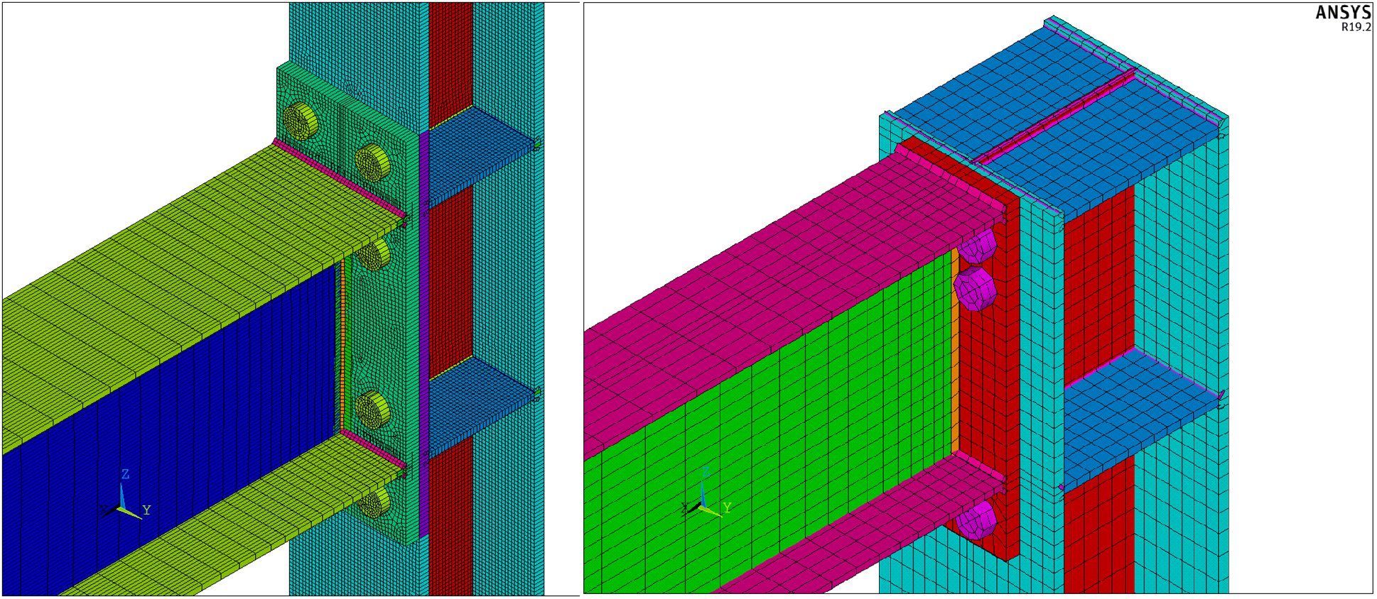
Figure 3: Detail of connection
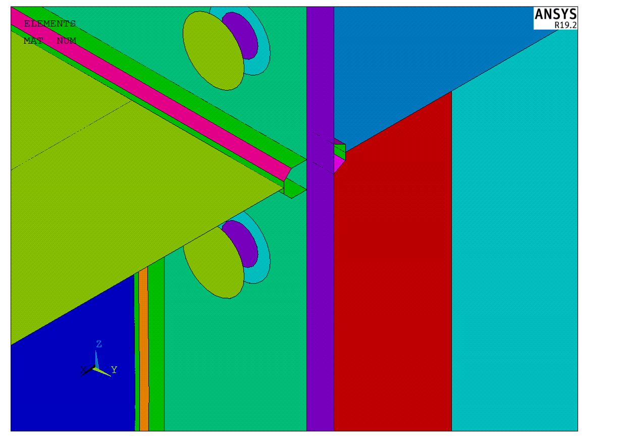
Figure 4: Detail of welds and bolts
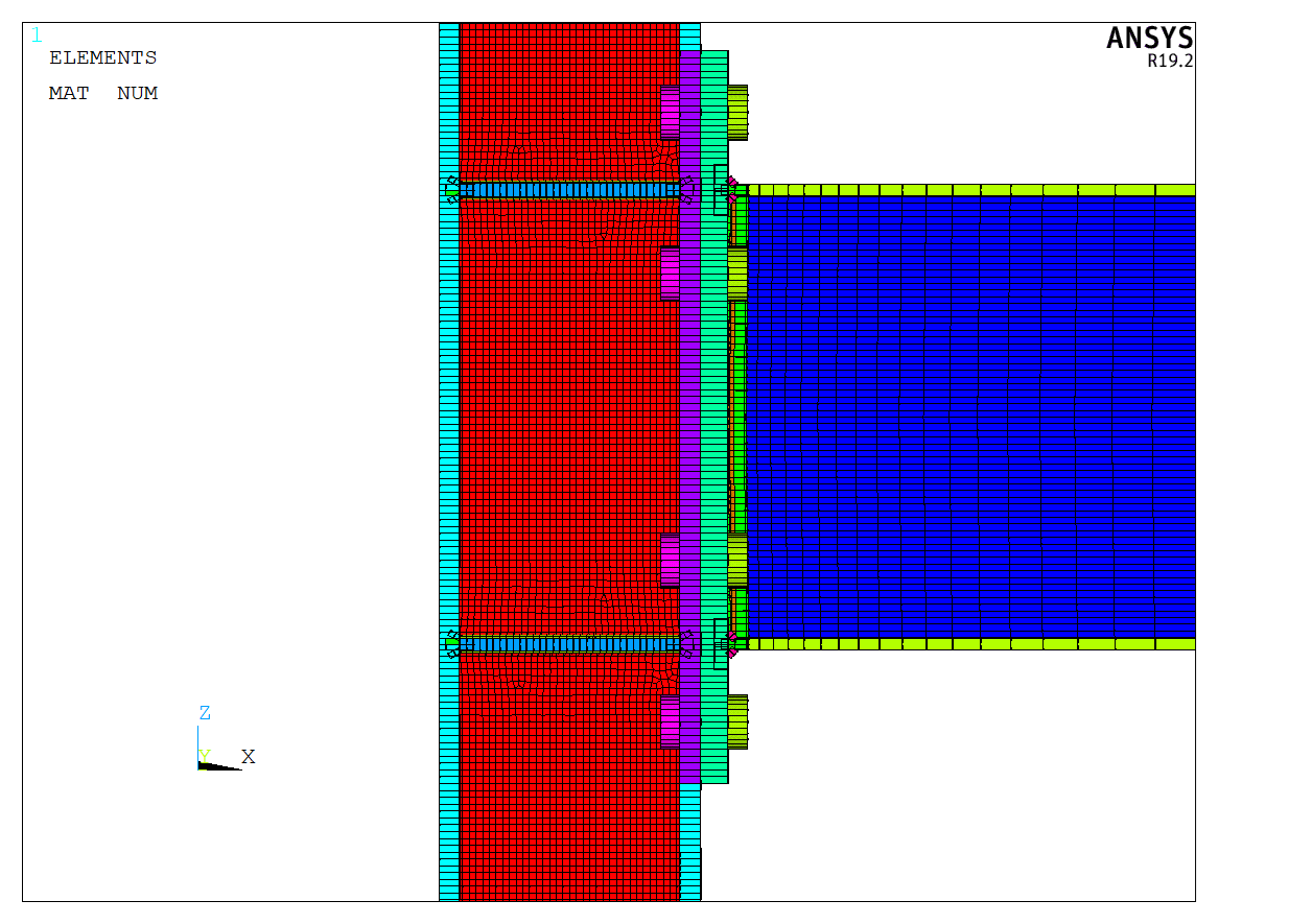
Figure 5: Shell elements displayed with their thickness – side view
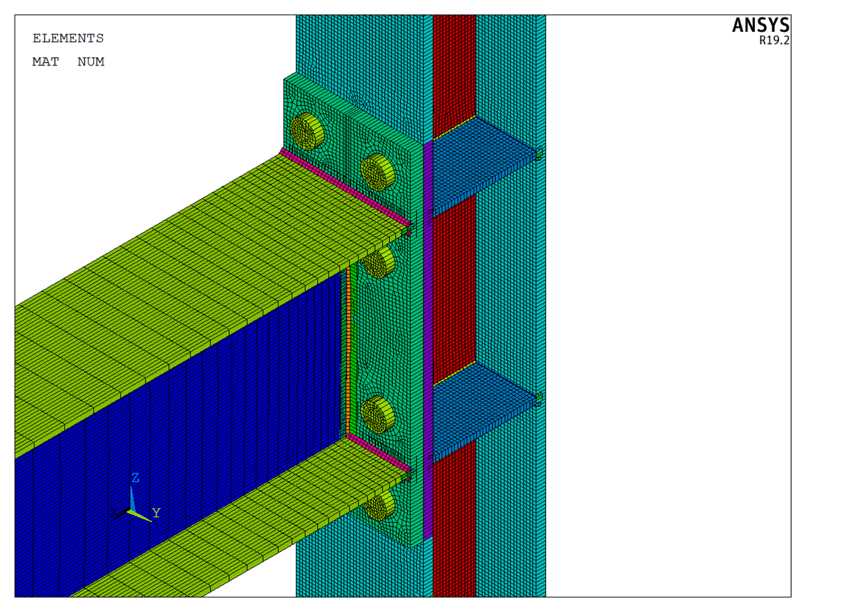
Figure 6: Shell elements displayed with their thickness – axonometry
Comparison of results
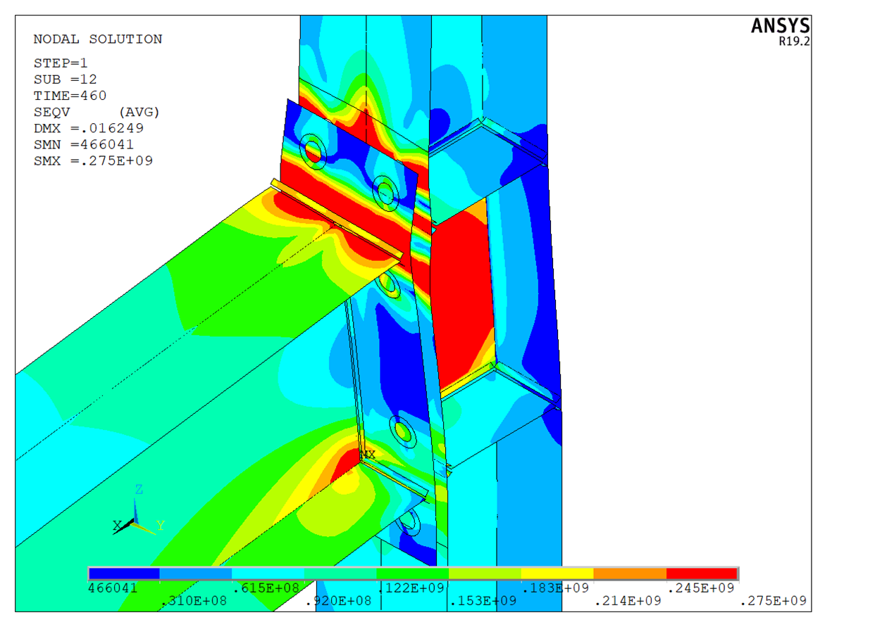
Figure 7: ANSYS model – von Mises stress – axonometry
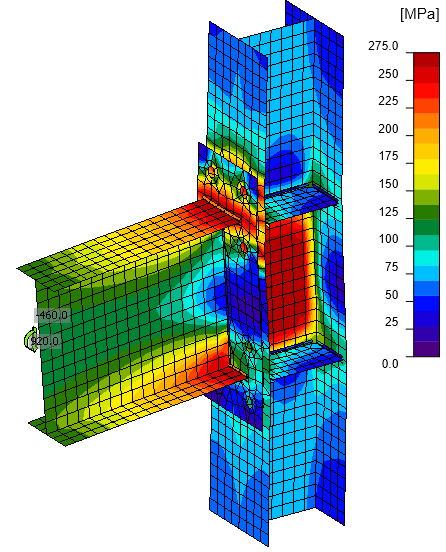
Figure 8: IDEA StatiCa model – von Mises stress – axonometry
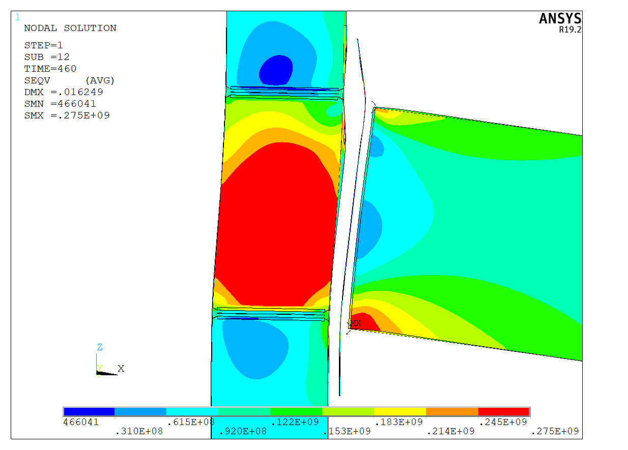
Figure 9: ANSYS model – von Mises stress – side view
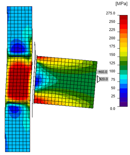
Figure 10: IDEA StatiCa model – von Mises stress – side view
Figure 11: Column rear flange – von Mises stress
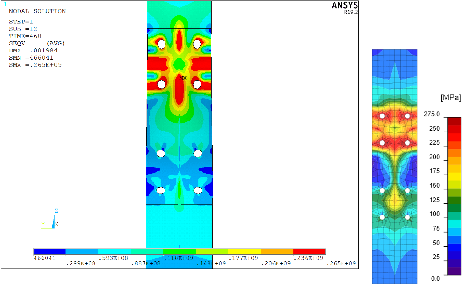
Figure 12: Column front flange (at end plate) – von Mises stress
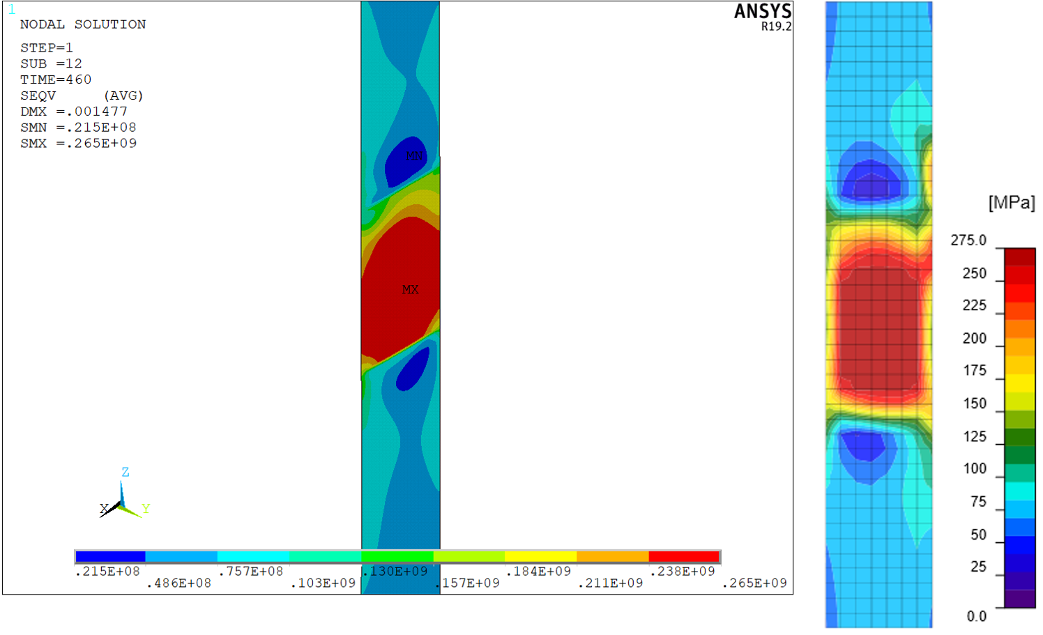
Figure 13: Column web – von Mises stress
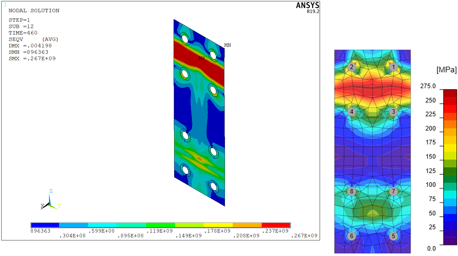
Figure 14: End plate – von Mises stress
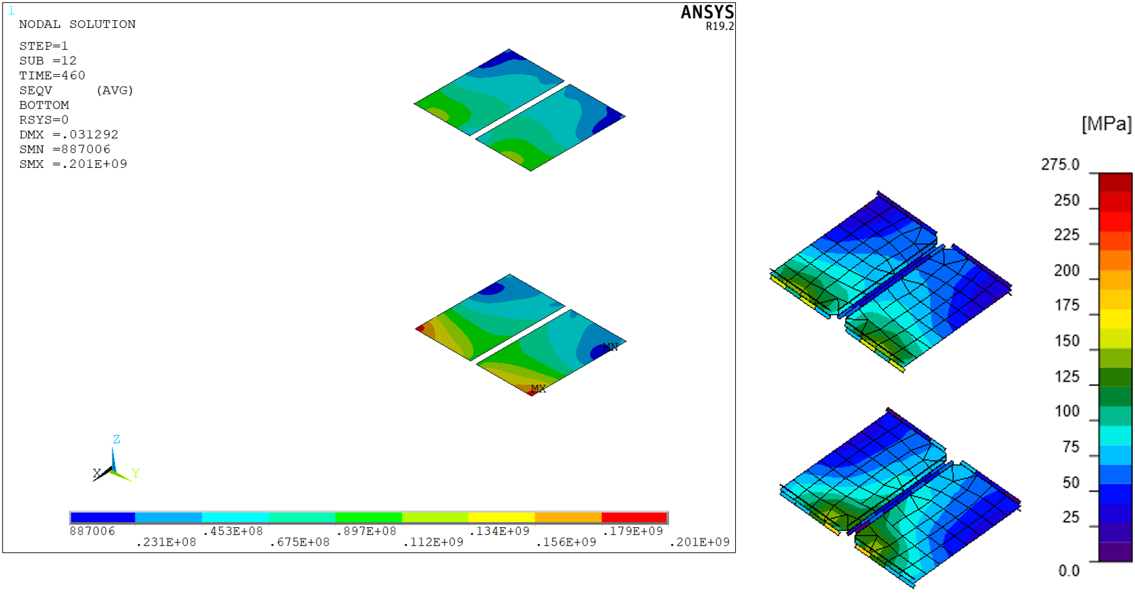
Figure 15: Column stiffeners (continuing plates)
The distribution of von Mises stress in both models is nearly identical. Minor differences are attributed to finer mesh in ANSYS model and differences in the modeling of bolts, welds, and contacts. Note that IDEA StatiCa uses a constant scale but the scale in ANSYS varies.
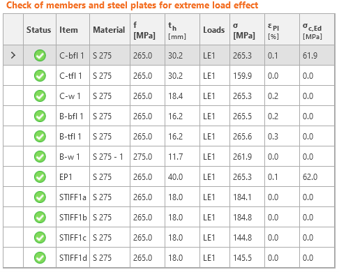
The peak stresses are also very similar, as can be seen in the following tables. A slightly bigger difference is in the peak plastic strain of the end plate. Again, this is caused by finer mesh and differences in the modeling of bolts and welds.
Table 1: Stresses and strains at plates – ANSYS
| Material | Thickness [mm] | [MPa] | [-] | |
| C-bfl1 | S275 | 30.2 | 265 | 0.3 |
| C-tfl1 | S275 | 30.2 | 214 | |
| C-w1 | S275 | 18.4 | 265 | 0.1 |
| b-bfl1 | S275 | 16.2 | 265 | 0.07 |
| B-tfl1 | S275 | 16.2 | 265 | 0.05 |
| B-w1 | S275 | 11.7 | 275 | 0.01 |
| EP1 | S275 | 40 | 267 | 0.9 |
| STIFF1a | S275 | 18 | 201 | |
| STIFF1b | S275 | 18 | 201 | |
| STIFF1c | S275 | 18 | 118 | |
| STIFF1d | S275 | 18 | 118 |
Table 2: Stresses and strains at plates – IDEA StatiCa
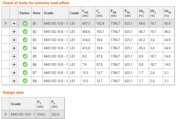
Differences are higher in the case of bolts. In IDEA StatiCa, the bolt forces in two top rows are always higher. That is caused due to the occurrence of prying forces. That is most probably caused by the higher stiffness of bolts in IDEA StatiCa in tension and a stiffer contact. The prying forces in IDEA StatiCa tend to decrease when bolts are more heavily loaded, bolts yield, deform more, and the stresses in contacts dissipate. The behavior of T-stub in IDEA StatiCa and the occurrence of prying forces are described for example here. The differences between shear forces can be attributed to the difference between contacts. Contact in ANSYS model is with the commonly used coefficient of friction 0.3. On the other hand, IDEA StatiCa uses frictionless contact, which is the safest assumption.
Table 3: Forces in bolts – ANSYS
| Tensile force [kN] | Shear force [kN] | |
| B1 | 304 | 83 |
| B2 | 304 | 83 |
| B3 | 334 | 44 |
| B4 | 334 | 44 |
| B5 | 34.6 | 71 |
| B6 | 34.6 | 71 |
| B7 | 37.1 | 37 |
| B8 | 37.1 | 37 |
Table 4: Forces in bolts – IDEA StatiCa
The welds are difficult to evaluate in ANSYS because of the presence of stresses that are neglected in design. However, good compliance between IDEA StatiCa and ANSYS was achieved. Overall, the stresses at significant welds, such as beam to end plate welds, in IDEA StatiCa are slightly higher, meaning its design is safer. In the case of some stiffener welds, the stresses in ANSYS were found higher.
Table 5: Stresses in welds – comparison of ANSYS and IDEA StatiCa
| Item | Edge | a [mm] | ANSYS fw [MPa] | IDEA StatiCa fw [MPa] |
| EP1 | B-bfl 1 | ◢10.0◣ | 202.1 | 217.6 |
| ◢10.0◣ | 207.5 | 218.4 | ||
| EP1 | B-tfl 1 | ◢10.0◣ | 214.1 | 217.5 |
| ◢10.0◣ | 196.4 | 216.6 | ||
| EP1 | B-w 1 | ◢6.0◣ | 215.1 | 218.2 |
| ◢6.0◣ | 215.1 | 218.2 | ||
| C-bfl 1 | STIFF1a | ◢8.0◣ | 106.3 | 144.6 |
| ◢8.0◣ | 206.2 | 190.6 | ||
| C-w 1 | STIFF1a | ◢8.0◣ | 201.1 | 68.6 |
| ◢8.0◣ | 61.0 | 65.9 | ||
| C-tfl 1 | STIFF1a | ◢8.0◣ | 90.4 | 76.3 |
| ◢8.0◣ | 65.1 | 60.8 | ||
| C-bfl 1 | STIFF1b | ◢8.0◣ | 195.1 | 191.8 |
| ◢8.0◣ | 129.2 | 145.5 | ||
| C-w 1 | STIFF1b | ◢8.0◣ | 207.1 | 65.9 |
| ◢8.0◣ | 63.6 | 68.7 | ||
| C-tfl 1 | STIFF1b | ◢8.0◣ | 110.0 | 60.8 |
| ◢8.0◣ | 86.5 | 76.3 | ||
| C-bfl 1 | STIFF1c | ◢8.0◣ | 157.5 | 162.2 |
| ◢8.0◣ | 135.2 | 158.1 | ||
| C-w 1 | STIFF1c | ◢8.0◣ | 29.4 | 67.6 |
| ◢8.0◣ | 28.2 | 65.8 | ||
| C-tfl 1 | STIFF1c | ◢8.0◣ | 54.4 | 51.8 |
| ◢8.0◣ | 74.4 | 66.5 | ||
| C-bfl 1 | STIFF1d | ◢8.0◣ | 137.6 | 159.8 |
| ◢8.0◣ | 161.1 | 163.7 | ||
| C-w 1 | STIFF1d | ◢8.0◣ | 87.9 | 65.8 |
| ◢8.0◣ | 92.4 | 67.6 | ||
| C-tfl 1 | STIFF1d | ◢8.0◣ | 65.4 | 66.5 |
| ◢8.0◣ | 54.2 | 51.8 |
Example 2
Example 2 is a beam-to-column joint. The beam has a cross-section UB 356 x 127 x 33. The column has a cross-section UC 254 x 254 x 73 and is fixed at the bottom. All used steel is grade S275. End plate connection is equipped with six M24 grade 8.8 bolts. The factored load at the beam in the joint is calculated:
- My = 100 kNm
- Vz = 100 kN
ANSYS model
The ANSYS model has a column with a length of 1 606 mm, which corresponds to IDEA StatiCa model. The column is fixed at the bottom. The beam is modelled as a cantilever with a length of 1 000 mm (node to end) and loaded by a downward force of 100 kN evenly distributed among the nodes simulating the beam web. Unlike IDEA StatiCa model, the column and the beam are created by shell elements along the whole length.
5 036 SHELL 181 elements were used to create the model. That led to 25 152 equations with a matrix width of 126. To finish the analysis, 11 substeps and 22 iterations were needed.
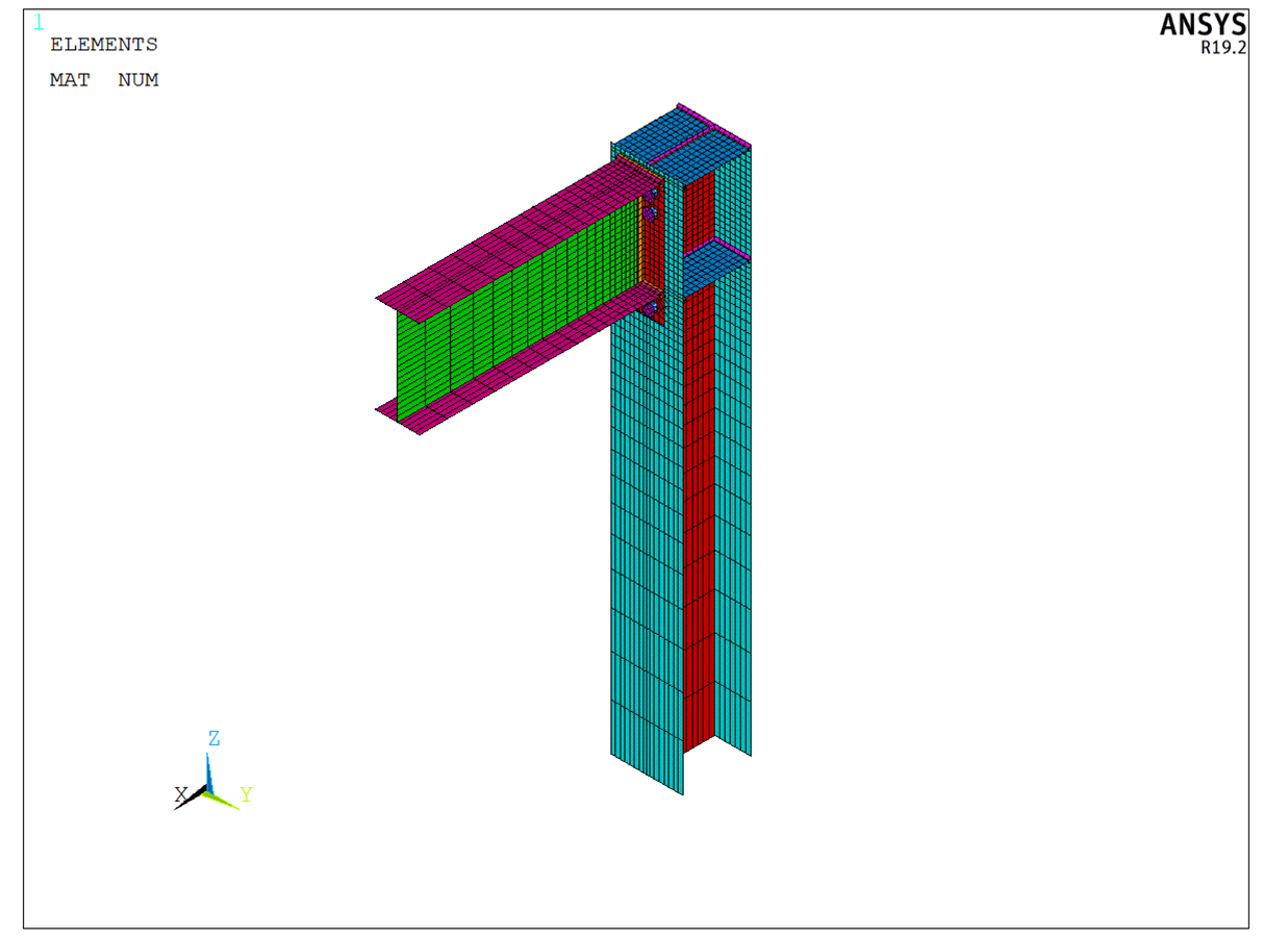
Figure 16: ANSYS model – axonometry
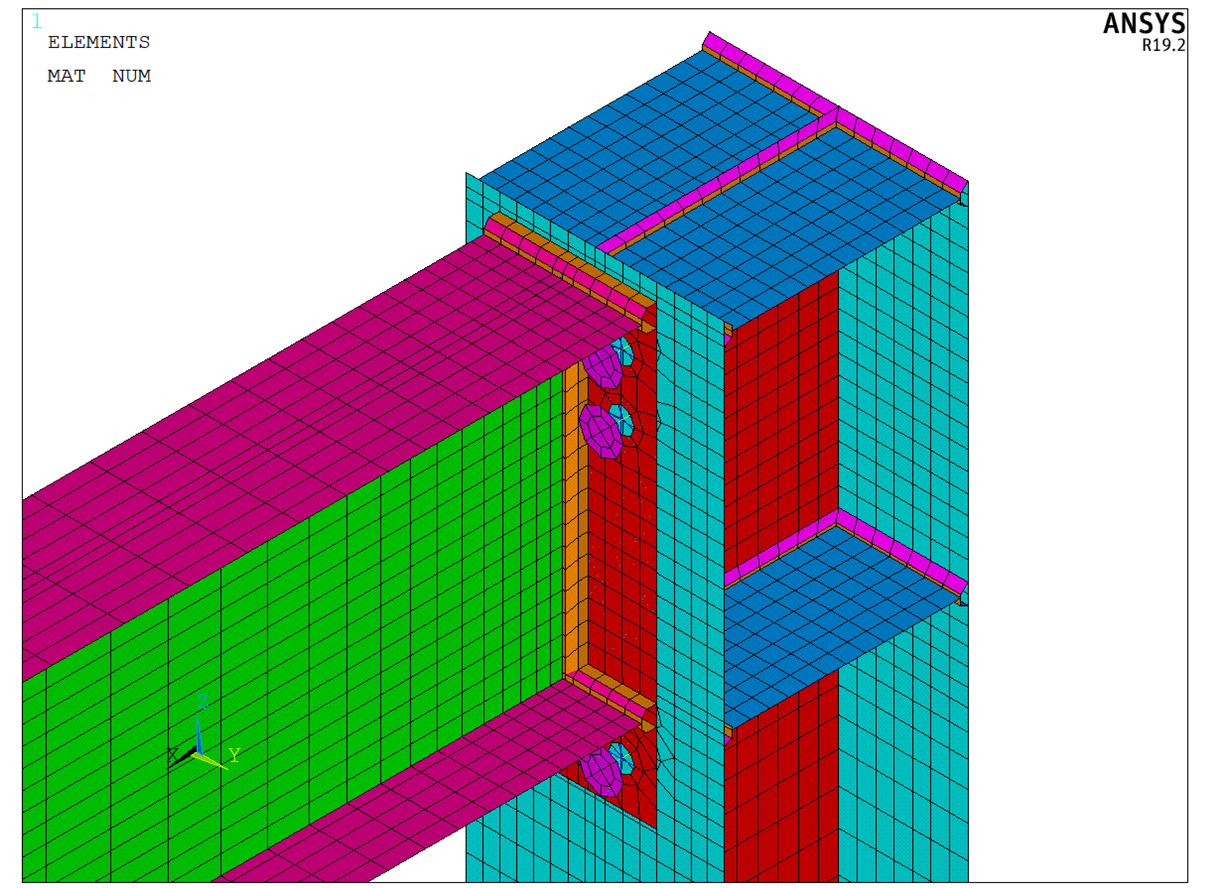
Figure 17: ANSYS model – detail at joint
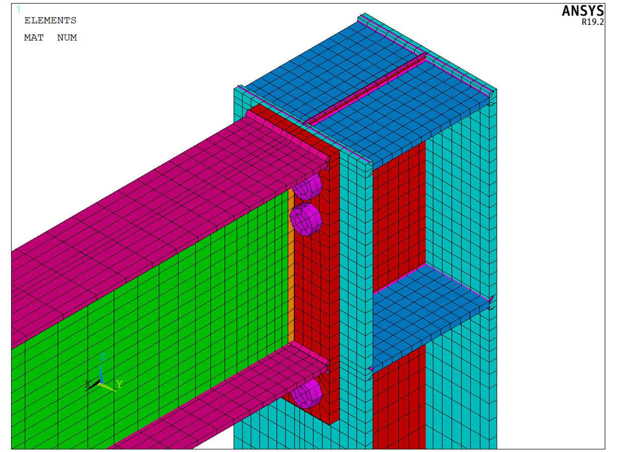
Figure 18: ANSYS model – with shell element thickness
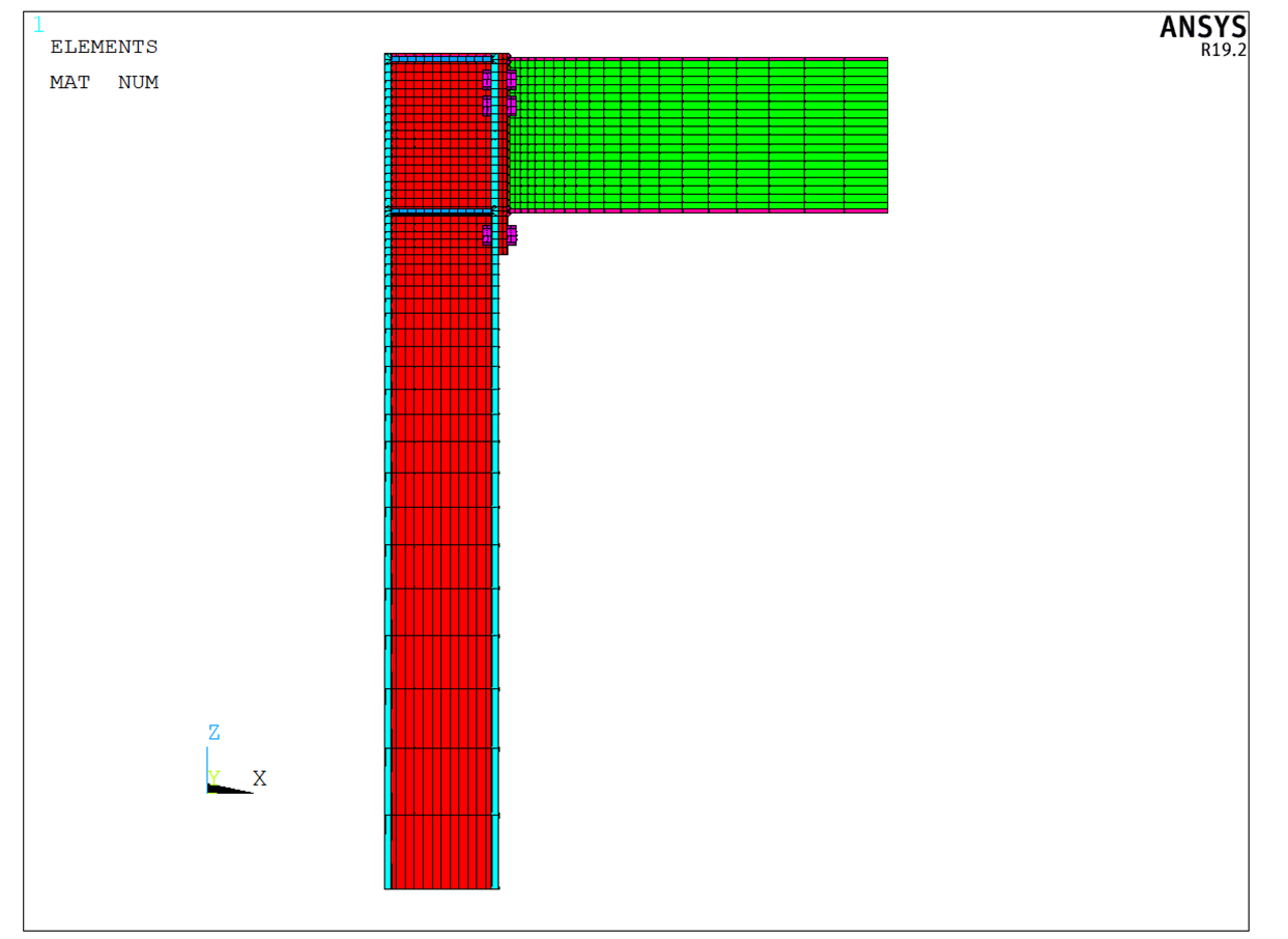
Figure 19: ANSYS model – side view with shell element thickness
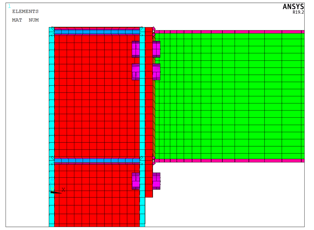
Figure 20: ANSYS model – side view with shell element thickness – detail of joint
Comparison of results
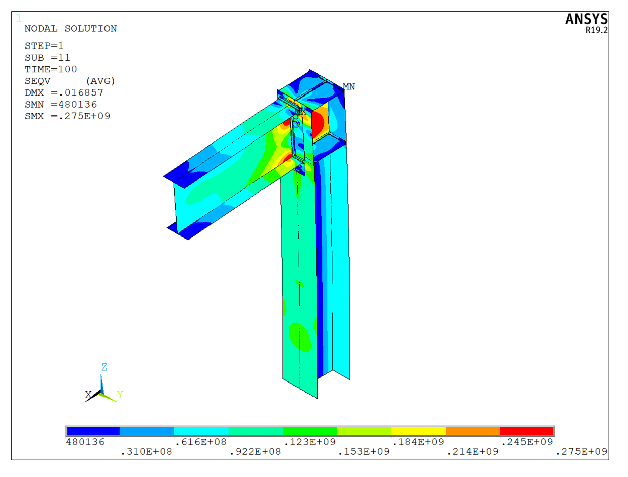
Figure 21: ANSYS – Axonometry – von Mises stress
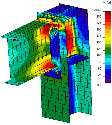
Figure 22: IDEA StatiCa – Axonometry – von Mises stress
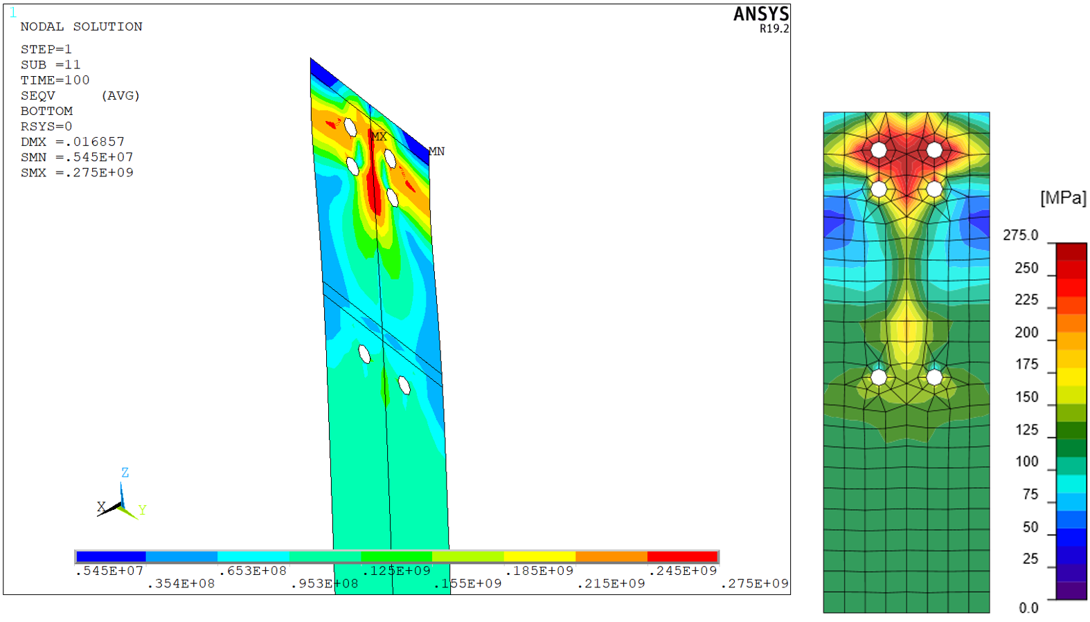
Figure 23: Column flange at end plate – von Mises stress
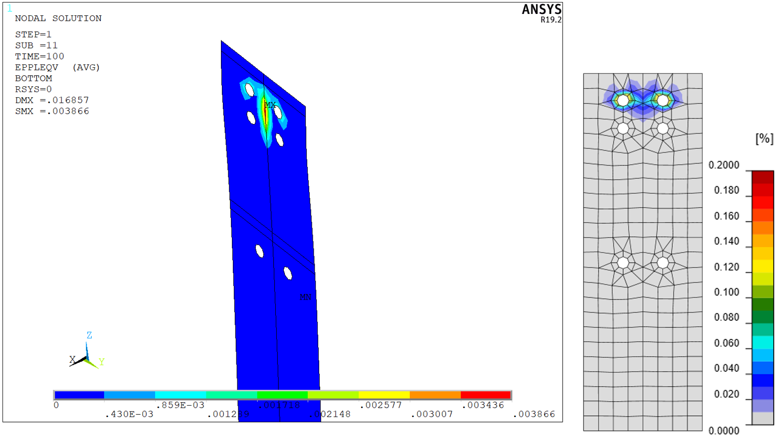
Figure 24: Column flange at end plate – plastic strain
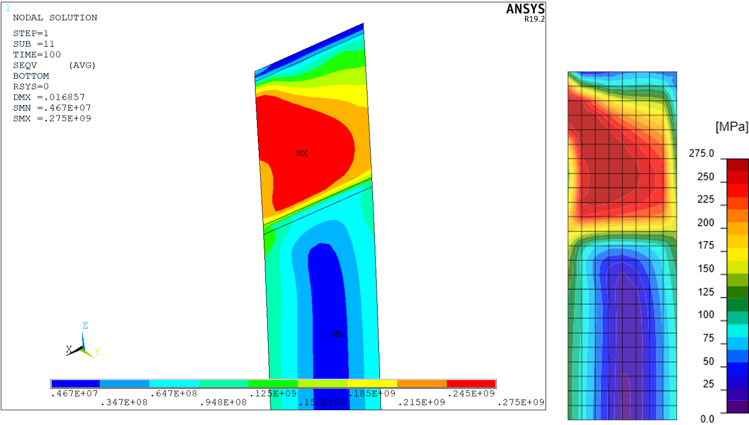
Figure 25: Column web – von Mises stress
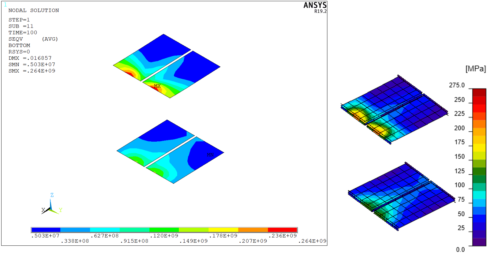
Figure 26: Column stiffeners – von Mises stress
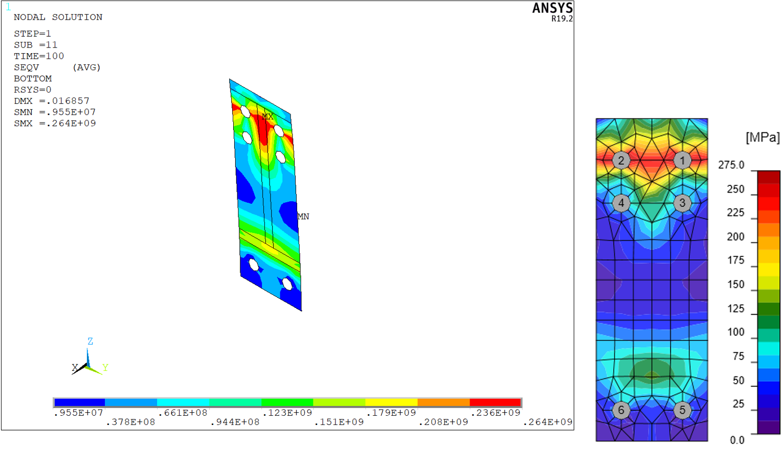
Figure 27: End plate – von Mises stress
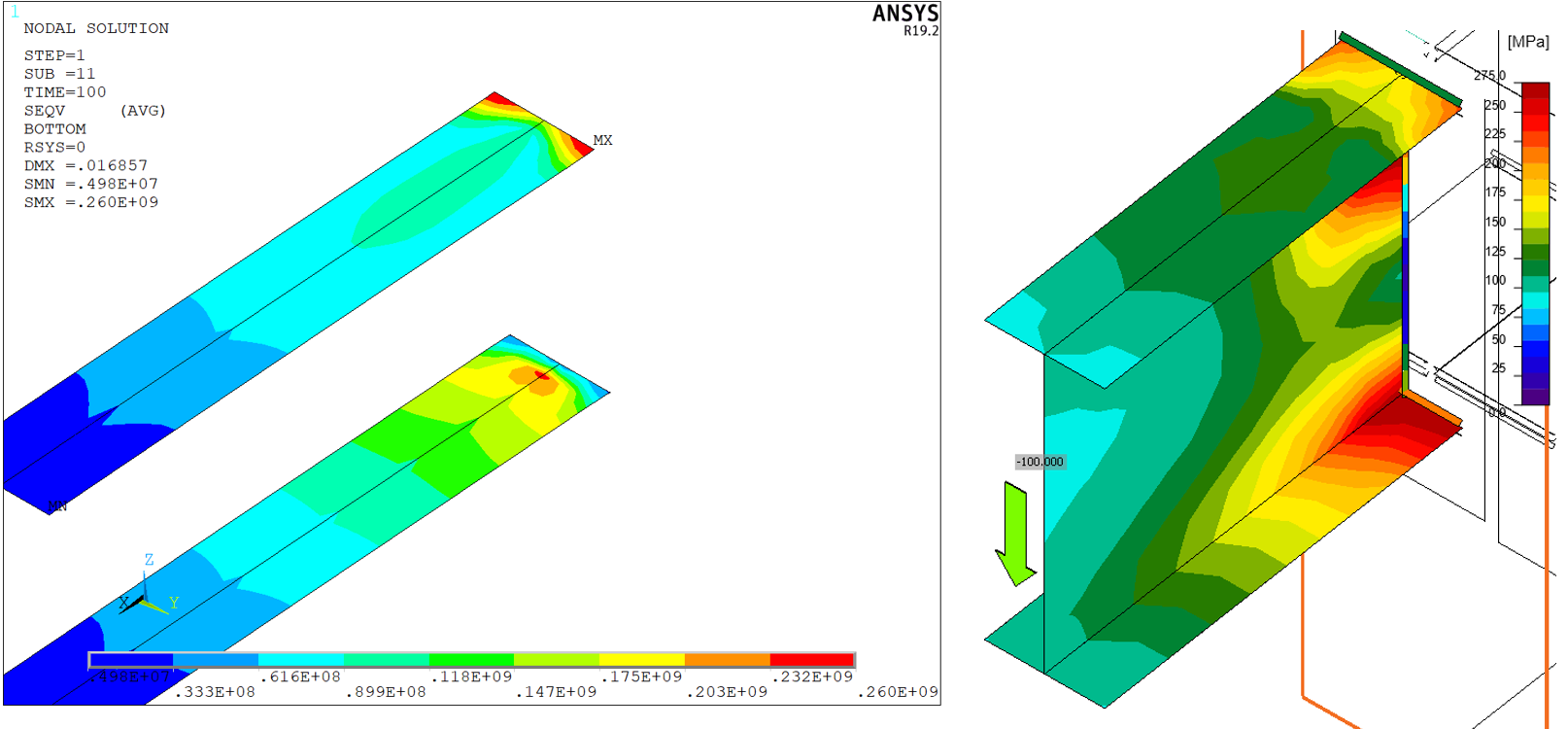
Figure 28: Beam flanges – von Mises stress
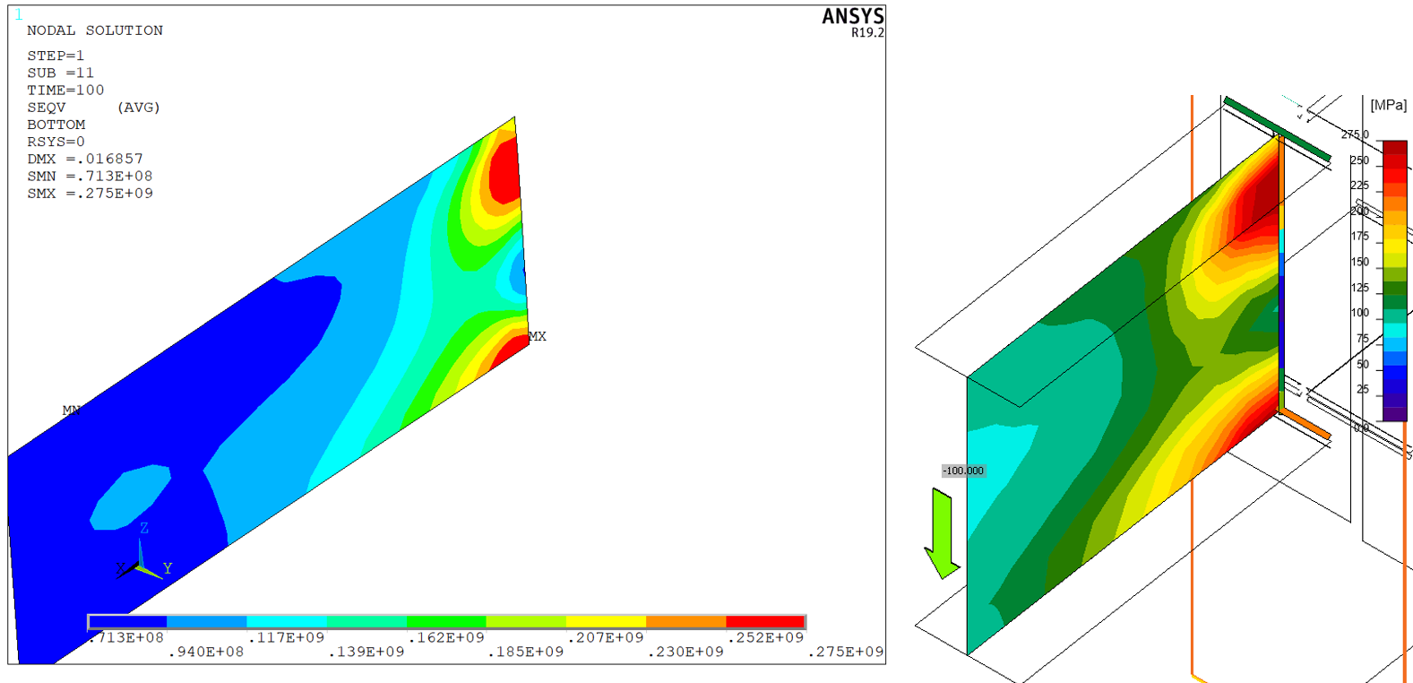
Figure 29: Beam web – von Mises stress
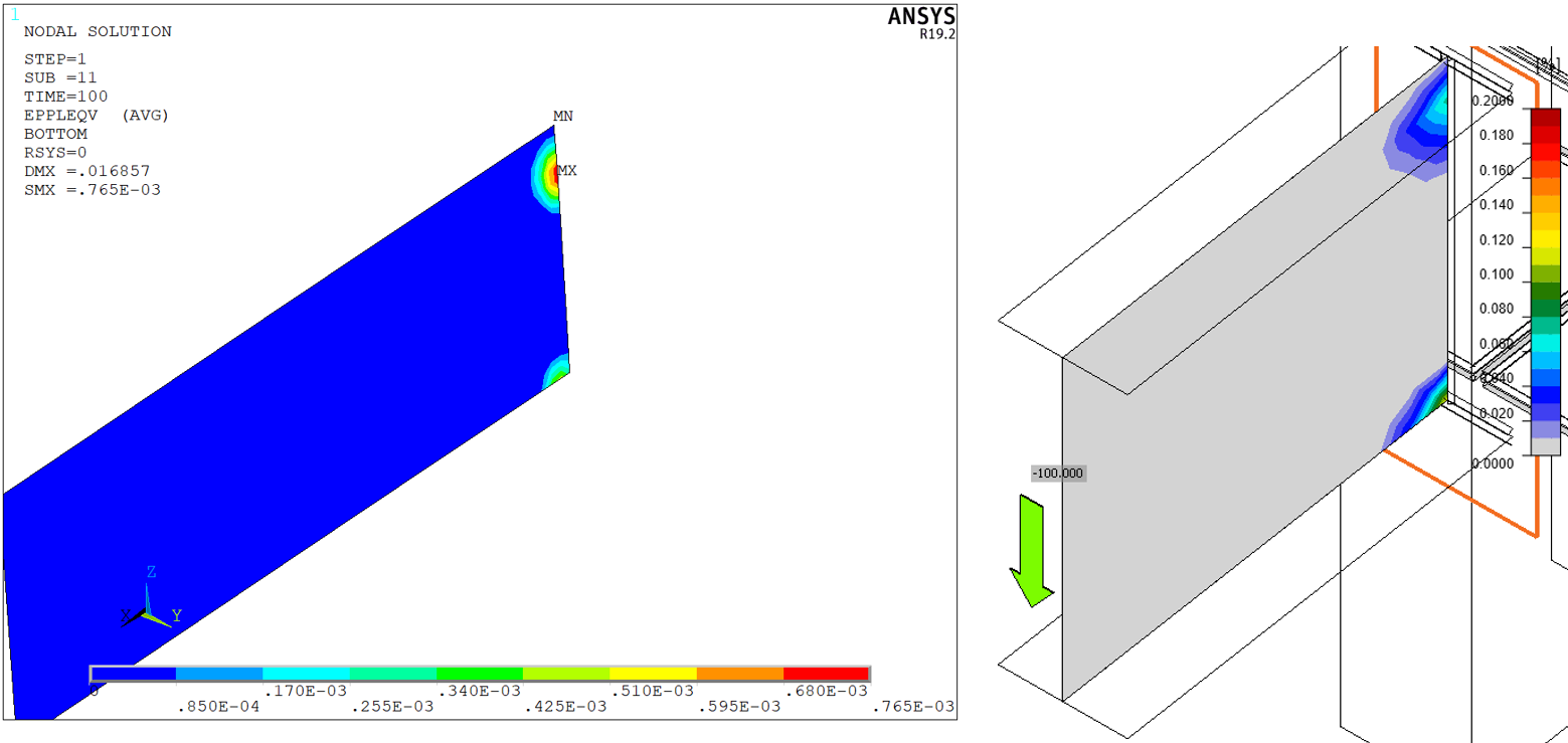
Figure 30: Beam web – plastic strains
The distribution of von Mises stress in both models is nearly identical. Minor differences are attributed to finer mesh in ANSYS model and differences in the modeling of bolts, welds, and contacts. Note that IDEA StatiCa uses a constant scale but the scale in ANSYS varies.
The peak stresses are also very similar, as can be seen in the following tables. A slightly bigger difference is in the peak plastic strain of the end plate. Again, this is caused by finer mesh and differences in the modeling of bolts and welds.
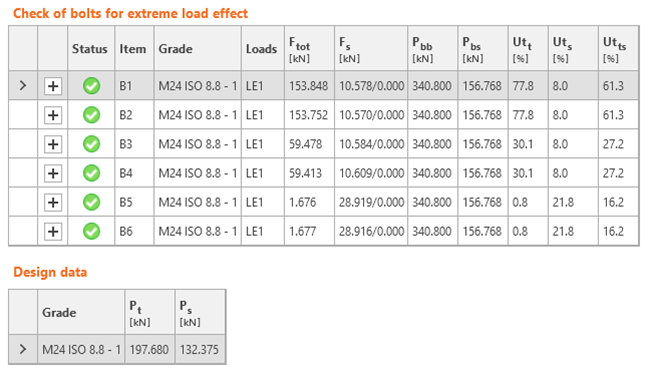
Table 6: Stresses and strains at plates – ANSYS
| Material | Thickness [mm] | [MPa] | [-] | |
| C-bfl1 | S275 | 14.2 | 174 | |
| C-tfl1 | S275 | 14.2 | 275 | 0.386 |
| C-w 1 | S275 | 8.6 | 275 | 0.026 |
| B-bfl 1 | S275 | 8.5 | 246 | |
| B-tfl1 | S275 | 8.5 | 260 | |
| B-w1 | S275 | 6 | 275 | 0.077 |
| EP2 | S275 | 20 | 264 | |
| Stiff1a | S275 | 10 | 155 | |
| Stiff1b | S275 | 10 | 155 | |
| Stiff1c | S275 | 10 | 264 | |
| Stiff1d | S275 | 10 | 264 |
Table 7: Stresses and strains at plates – IDEA StatiCa
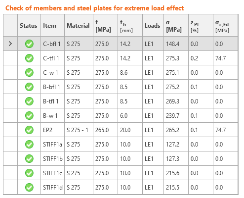
Table 8: Forces in bolts – ANSYS
| Tensile force | Shear force | |
| B1 | 104.2 | 14.7 |
| B2 | 104.2 | 14.7 |
| B3 | 47.1 | 14.3 |
| B4 | 47.1 | 14.3 |
| B5 | 12.1 | 21 |
| B6 | 12.1 | 21 |
Table 9: Forces and checks of bolts – IDEA StatiCa
Differences are higher in the case of bolts. In IDEA StatiCa, the bolt forces are always higher except for the bottom bolt row. That is caused due to the occurrence of prying forces. That is most probably caused by the higher stiffness of bolts in IDEA StatiCa in tension and a stiffer contact. The prying forces in IDEA StatiCa tend to decrease when bolts are more heavily loaded, bolts yield, deform more, and the stresses in contacts dissipate. The differences between shear forces can be attributed to the difference between contacts. Contact in ANSYS model is with the commonly used coefficient of friction of 0.3. On the other hand, IDEA StatiCa uses frictionless contact, which is the safest assumption.
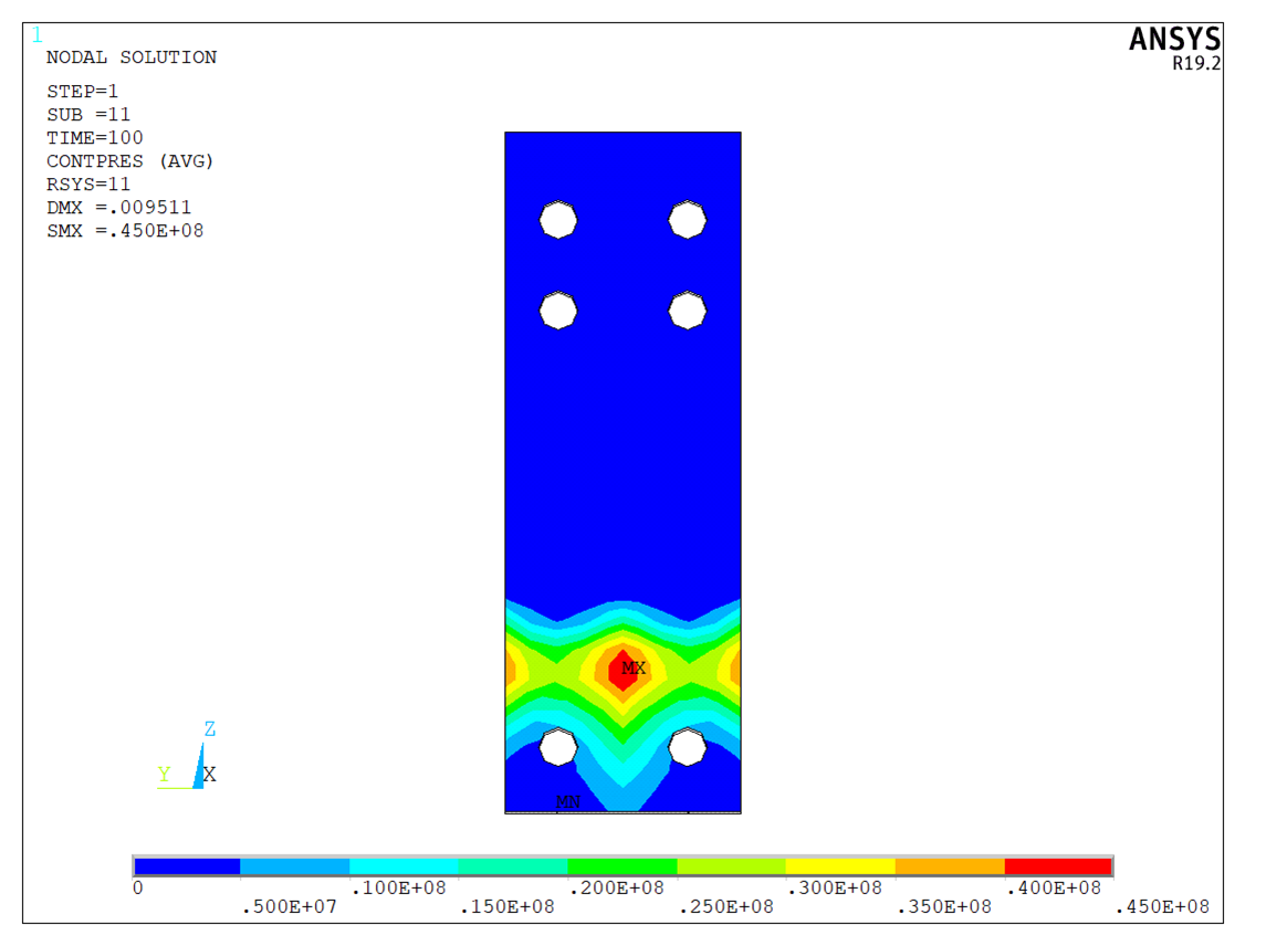
Figure 31: Contact stresses between end plate and column flange in ANSYS
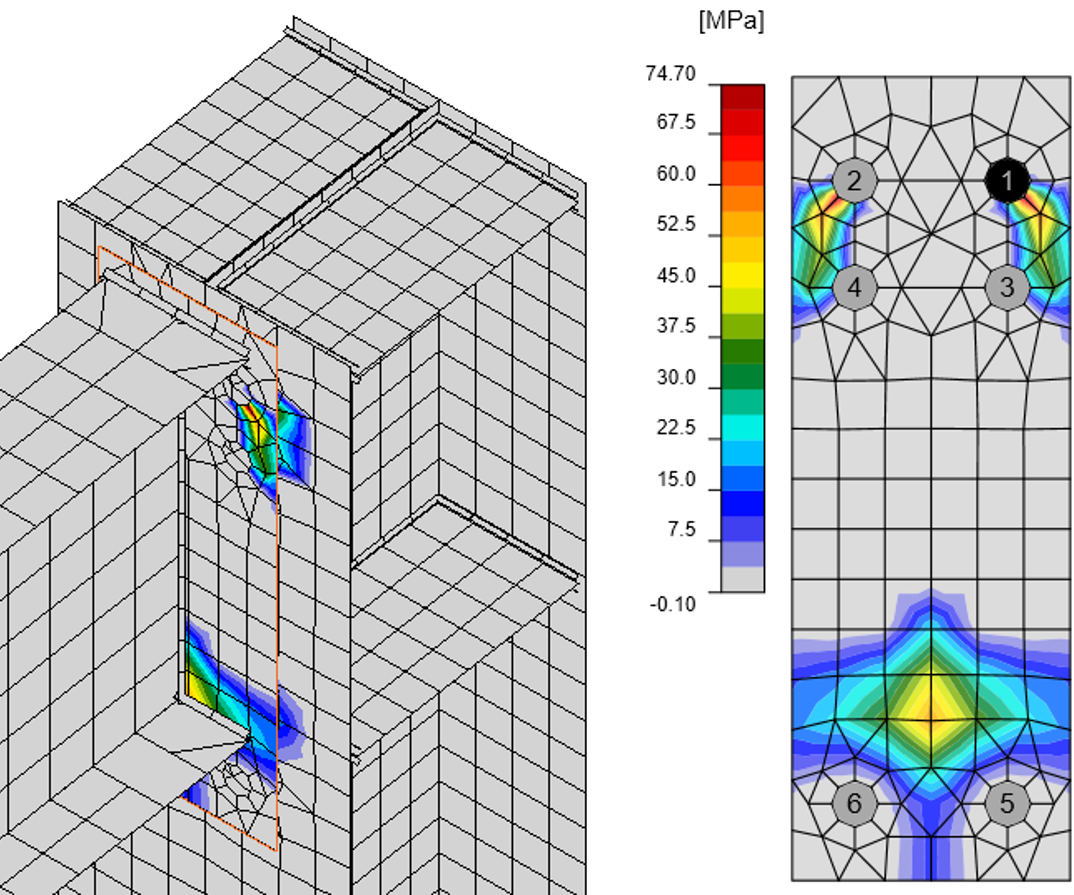
Figure 32: Contact stresses between end plate and column flange in IDEA StatiCa
The welds are difficult to evaluate in ANSYS because of the presence of stresses that are neglected in design. However, a good agreement between IDEA StatiCa and ANSYS was achieved. Overall, the stresses in IDEA StatiCa are slightly higher, meaning its design is safer.
Table 10: Stresses in welds
| Member | Weld | a [mm] | ANSYS fw [MPa] | IDEA StatiCa fw [MPa] |
| EP2 | B-bfl 1 | ◢6.0◣ | 218.0 | 215.7 |
| ◢6.0◣ | 166.5 | 215.7 | ||
| EP2 | B-tfl 1 | ◢6.0◣ | 129.2 | 120.7 |
| ◢6.0◣ | 88.3 | 135.9 | ||
| EP2 | B-w 1 | ◢5.0◣ | 219.1 | 215.6 |
| ◢5.0◣ | 219.1 | 215.6 | ||
| C-bfl 1 | STIFF1a | ◢4.0◣ | 40.8 | 41.5 |
| ◢4.0◣ | 60.8 | 57.3 | ||
| C-w 1 | STIFF1a | ◢4.0◣ | 47.5 | 61.2 |
| ◢4.0◣ | 37.9 | 57.5 | ||
| C-tfl 1 | STIFF1a | ◢4.0◣ | 167.1 | 137.2 |
| ◢4.0◣ | 111.0 | 105.7 | ||
| C-bfl 1 | STIFF1b | ◢4.0◣ | 62.7 | 57.2 |
| ◢4.0◣ | 41.8 | 41.4 | ||
| C-w 1 | STIFF1b | ◢4.0◣ | 47.5 | 57.6 |
| ◢4.0◣ | 66.4 | 61.2 | ||
| C-tfl 1 | STIFF1b | ◢4.0◣ | 120.2 | 105.4 |
| ◢4.0◣ | 167.4 | 136.9 | ||
| C-bfl 1 | STIFF1c | ◢4.0◣ | 58.8 | 32.2 |
| ◢4.0◣ | 30.8 | 30.8 | ||
| C-w 1 | STIFF1c | ◢4.0◣ | 83.2 | 80.9 |
| ◢4.0◣ | 65.4 | 82.4 | ||
| C-tfl 1 | STIFF1c | ◢4.0◣ | 174.0 | 215.8 |
| ◢4.0◣ | 164.3 | 214.3 | ||
| C-bfl 1 | STIFF1d | ◢4.0◣ | 19.6 | 30.8 |
| ◢4.0◣ | 20.9 | 32.2 | ||
| C-w 1 | STIFF1d | ◢4.0◣ | 73.9 | 82.4 |
| ◢4.0◣ | 96.6 | 80.9 | ||
| C-tfl 1 | STIFF1d | ◢4.0◣ | 163.3 | 214.0 |
| ◢4.0◣ | 173.6 | 215.8 |
Summary
Two beam-to-column joints were designed in IDEA StatiCa and compared to ANSYS. Steel connections can be modeled in a lot of ways. The goal was not to compare different modeling techniques but to verify IDEA StatiCa analysis model. Therefore, a similar modeling technique was used in ANSYS – shell elements for plates and welds, and beam elements for bolts. Mesh was denser in ANSYS model and it did not contain any special elements, such as multipoint constraints or elements with failure criteria based on codes, in this case, the Hong Kong code. Differences between ANSYS and IDEA StatiCa models are attributed to these modeling differences. However, the differences are very small; the stress and plastic strain patterns are nearly identical. The main difference is in the bolt forces, where IDEA StatiCa provides higher tensile forces, i.e. safer results than ANSYS. Stresses in welds are difficult to determine as opposed to IDEA StatiCa where special finite elements compliant with the code design requirements are used. Generally, there was a good agreement between weld stresses. The weld stresses were slightly higher in IDEA StatiCa, meaning that the design is safe.
References
[1] Ansys® Mechanical Enterprise, Release 19.2
[2] Hong Kong Buildings Department, Code of Practice for Structural Use of Steel 2011 (2021 Edition), available at https://www.bd.gov.hk/doc/en/resources/codes-and-references/code-and-design-manuals/SUOS2011.pdf
[3] Turlier D., Klein P., Bérard F. ¨Seam Sim¨ method for seam weld structural assessment within a global structure FEA. Proc. Int. Conf. IIW2010 Istanbul (Turkey). AWST 651-658, 2010.