Condensed superelements - invisible but essential
Until version 21 was released, there were not many ways to model the steel member connections more realistically than using the IDEA StatiCa application. But still, there were situations where the edge stress values were inaccurate and didn't correspond to the real behavior of the steel members. It wasn't easy to find the correct way to stay focused on the connection design, solve just the area close to the structural node and at the same time take into account the behavior of the rest of the connected members.
But the development team managed to find the way. They have enlarged the model drastically by adding member parts that are not visible but essential for the whole model. These parts are called condensed superelements and they do all the hard work with the behavior improvement.
This change secures that the ends of the members visible in the model scene are not the ends at all. In previous versions, the end sections were fixed in their plane and often non-realistic stress peaks could evolve here. Now, they can deplane – they can deform not only within the cross-section plane but also perpendicularly to this plane.
Especially with the hollow section connections, the results show better compliance with experimental tests and design code formulations.
On the other side, this change also means that the stress peaks originally located in the end sections can and will move closer to the connection node. In some cases, the connection elements can be exposed to bigger forces in 'condensed superelements times'.
Three benefits for you
This improvement brings also very convenient side effects – the member stubs simulated by shell elements may now be shorter. The main benefits of this change are:
- 30% faster calculation times on average
- Faster visualization of results
- More accurate modeling of hollow sections connections
Other great new features and improvements introduced in version 21 are specified in our detailed Release notes.
New lengths of members
Our users are used to the default lengths of the members in the connection design model. They were dependant on the type of the cross-section (hollow / opened).
Now the default length is set to the same value of 1.25 x the larger of the cross-section outer dimensions for both types. The length of the condensed superelements is 4 x the larger of the cross-section outer dimensions for standard stress-strain analysis. Because we wanted to keep the buckling mode shapes within the internal plates of the connection and not in the members, the length of the superelements for linear buckling and stiffness analysis is set to 0.5 x the larger of the cross-section outer dimensions.
Although these changes were originally made for the improvement of hollow section connections, they helped other types of connections to get closer to real behavior as well.
You may ask, what are the main consequences? With no doubt, some result changes between versions will occur. In the vast majority of the connections, the differences in results are below 1%.
Cases with bigger differences bring a highlight to the topic where practice collides with theory. This topic is related to torsion effects on open-section profiles. For several reasons these effects are neglected by structural engineers and they're neither embedded in the FEM global analysis applications.
Torsion effects
Well, it's not rocket science, but it doesn't have to be obvious either. So, let's bring in some theory:
Being dependent on the type of open cross-section, member boundary conditions and type of loading, two kinds of torsion behavior may occur, considering Vlasov's hypothesis:
- Pure (St. Venant) torsion
- Mixed torsion combined of pure torsion and warping torsion
- pure torsion is characterized by internal force Tt (pure torsion moment) with resulting pure shear stress τt
- warping torsion is characterized by internal forces B (bimoment) and Tw (warping torsion moment) with resulting warping normal (longitudinal) stress σw and warping torsion shear stress τw

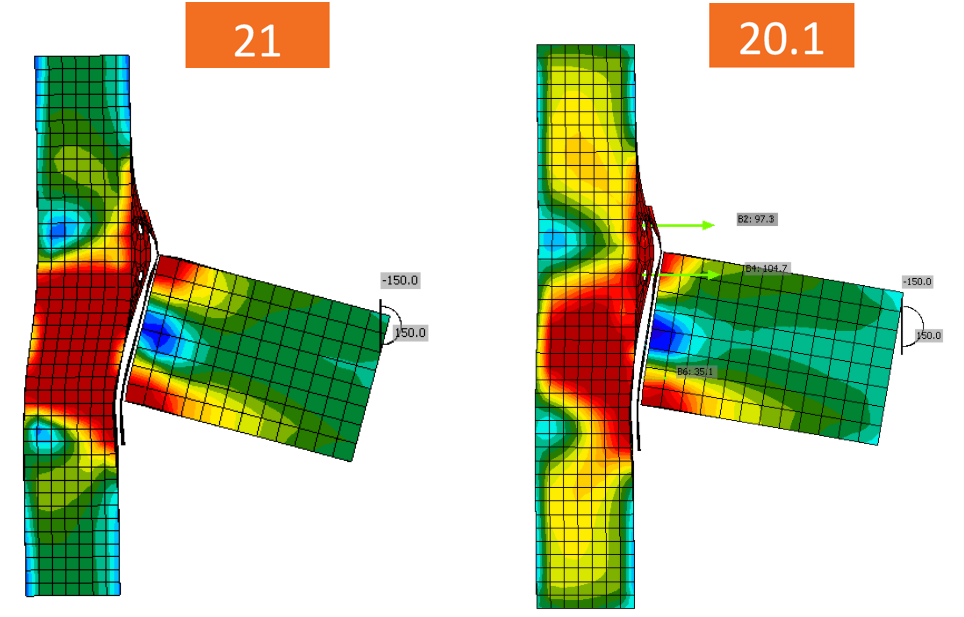
In IDEA StatiCa Connection version 21.0, the warping was restrained by the multipoint constraints connecting the node with the beam end. These constraints are used to impose loads into the model. The new condensed superelement pushes the restraints further and the member is able to deform. This results in a bigger bimoment in the connection.
Here you can see a few connection examples, where these changes resulted in the significantly different outcome:
The beam stub under torsion
One-sided end-plate beam-to-beam connection
Beam-to-column connection
When you deal with such cases, especially if you compare results between versions, you should keep in mind that the calculation models are not the same. The members are longer and the stiffness of the connection is smaller. So the differences in results may be expectable in some connection elements.
But you have always some options to check to avoid incorrect outputs. From version 21 on, it's more important than ever, to use the 'Loads in equilibrium' feature.

You may often want to check the connection model created in the older version in the most recent one. Then you shouldn't forget to set the parameters in the Code setup to the new default values, just not to mix apples with oranges.

However, if you want to be 100 % sure that your IDEA StatiCa application version 21.0 works with the best data possible, then model the whole calculation model in version 21 from scratch.
If you're interested in the theoretical background behind the improvements introduced in version 21, you can find very useful and thoroughly prepared information from our specialists in this knowledge base article.