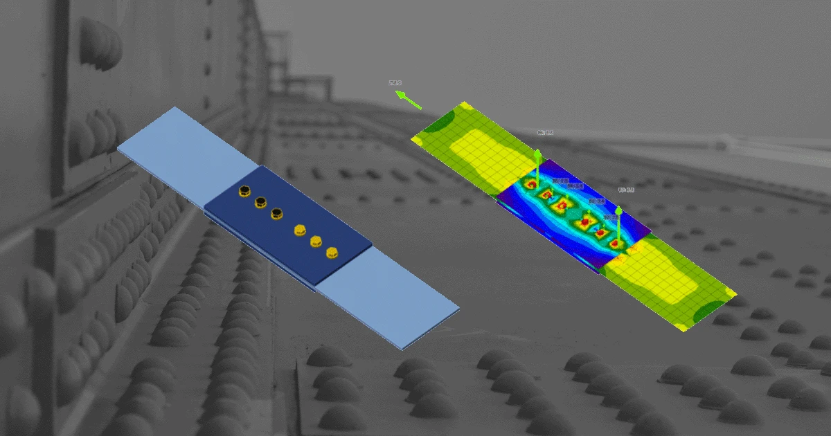


Bolt model according to CBFEM
IDEA StatiCa has a unique method in its solver, the Component-based Finite Element Method (CBFEM). The bolt model used in CBFEM is described and verified to several steel design codes. The load resistance and deformation capacity are also compared to the main experimental research programs.
In the Component-Based Finite Element Method (CBFEM), bolt with its behavior in tension, shear, and bearing is the component described by the dependent nonlinear springs. The bolt in tension is described by spring with its axial initial stiffness, design resistance, initialization of yielding, and deformation capacity. For the initialization of yielding and deformation capacity, it is assumed that plastic deformation occurs in the threaded part of the bolt shank only.
In our Theoretical background, you can find more information on how the CBFEM method describes and verifies bolts. If you want to know a bit more about CBFEM in general, the full General theoretical background is definitely the best place to start from.
Bolts according to design codes
Let's take a look at how CBFEM approaches bolts from the point of view of individual design codes. So far, IDEA StatiCa supports eight design codes where design and/or detailing of bolts and preloaded bolts are being solved.
Check of bolts and preloaded bolts according to Eurocode
The initial stiffness and design resistance of bolts in shear are in CBFEM modeled according to Cl. 3.6 and 6.3.2 in EN 1993-1-8. The spring representing bearing and tension has a bi-linear force-deformation behavior with an initial stiffness and design resistance according to Cl. 3.6 and 6.3.2 in EN 1993-1-8.
Detailing
Checks of bolts is performed if the option is selected in Code setup. Dimensions from bolt center to plate edges and between bolts are checked. Edge distance e = 1.2 and spacing between bolts p = 2.2 are recommended in Table 3.3 in EN 1993-1-8. Users can modify both values in the Code setup.
Check of bolts and preloaded bolts according to AISC
The forces in bolts are determined by finite element analysis. The tensile forces include prying forces. The bolt resistances are checked according to AISC 360 - Chapter J3.
Detailing
The minimum spacing between bolts and distance to the bolt center to an edge of a connected part is checked. The minimum spacing 2.66 times (editable in Code setup) the nominal bolt diameter between centers of bolts is checked according to AISC 360-16 – J.3.3. The minimum distance to the bolt center to an edge of a connected part is checked according to AISC 360-16 – J.3.4; the values are in Table J3.4 and J3.4M.
Check of bolts and preloaded bolts according to other standards
Bolt detailing
How to set the distances
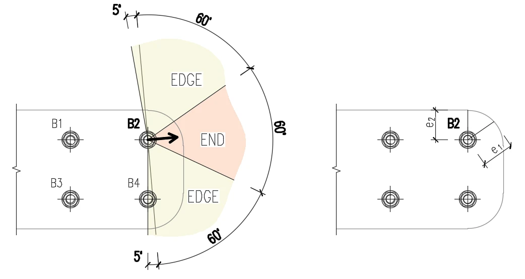
Edge distances used for bolt bearing resistance must be relevant for general plate geometries, plates with openings, cutouts, etc.
The algorithm reads the real direction of the resulting shear force vector in a given bolt and then calculates the distances needed for the bearing check.
The end (e1) and edge (e2) distances are determined by dividing the plate contour into three segments. The end segment is indicated by a 60° range in the direction of the force vector. The edge segments are defined by two 65° ranges perpendicular to the force vector. The shortest distance from a bolt to a relevant segment is then taken as an end, or an edge distance.
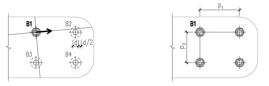
The spacing distances between bolt holes (p1; p2) are determined by virtually enlarging the surrounding bolt holes by a half of their diameter, then drawing two lines in direction and perpendicular to the shear force vector. The distances to the enlarged bolt holes that are intersected by these lines are then considered as p1 and p2 in the calculation.
Verification examples
We have prepared several verification examples to check the results in comparison with other computation methods.
EN
AISC
Patented technology for structural engineers
Do you know that our bolt model solution is a part of a U.S. patent? Read here about our success story.

One bolt joint - our solution
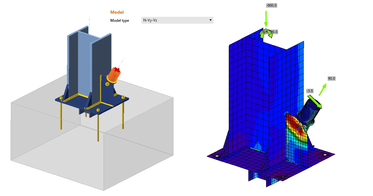
Sometimes, the engineer needs to make a joint with one bolt only, especially if e.g. a hinge, a bracing, a rod, or a diagonal is expected. To model and calculate this kind of operation, you need to define a proper Model type of the member. More about it can be read here.
Bolts, welds, and stiffness of a joint
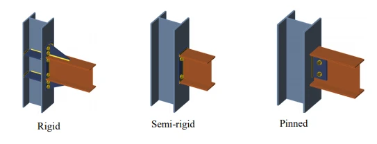
Both bolts and welds have their advantages and disadvantages. One of the important aspects when choosing a joint is its planned stiffness. In general, a bolted joint is never as rigid as a welded joint. If you choose a bolt connection, we recommend calculating the stiffness of such a connection and taking into account the resulting stiffness in the overall structure. You can read what such a calculation looks like and what it entails here, or watch this video.
Widget #NaN: widget_iframe
Name: iframe widget - Newsletter Subscription
ID: a1697b47-e5f7-4009-8b18-a29b3b27db65
Show Raw Data
{
  "iframe_title": {
    "name": "Title",
    "type": "text",
    "value": "Join 10,000 fellow Engineers"
  },
  "iframe_description": {
    "name": "Description",
    "type": "text",
    "value": "Get expert engineering tips straight to your inbox. \nSubscribe to the IDEA StatiCa Newsletter below."
  },
  "iframe_url": {
    "name": "iframe URL",
    "type": "text",
    "value": "https://campaign.ideastatica.com/newsletter-subscription"
  },
  "iframe_height": {
    "name": "Height",
    "type": "number",
    "value": 650
  },
  "iframe_width": {
    "name": "Width",
    "type": "number",
    "value": 850
  },
  "visibleinregion": {
    "name": "VisibleInRegion",
    "type": "multiple_choice",
    "value": []
  },
  "regions": {
    "name": "Region",
    "type": "taxonomy",
    "value": [],
    "taxonomyGroup": "region"
  },
  "translation__translation_connector": {
    "name": "Translation Connector",
    "type": "taxonomy",
    "value": [],
    "taxonomyGroup": "languages"
  },
  "translation__force_translation": {
    "name": "Force translation",
    "type": "multiple_choice",
    "value": []
  },
  "translation__translate_standalone_nested_content_items": {
    "name": "Translate standalone nested content items",
    "type": "multiple_choice",
    "value": []
  },
  "translation__last_translation": {
    "images": [],
    "linkedItemCodenames": [],
    "linkedItems": [],
    "links": [],
    "name": "Last translation",
    "type": "rich_text",
    "value": "<p>Translation info:</p>\n<ul>\n  <li>cs-CZ: Translated on 29.5.2026 12:04</li>\n  <li>de-DE: Translated on 29.5.2026 12:42</li>\n  <li>en-US: Never translated</li>\n  <li>es-ES: Translated on 29.5.2026 14:29</li>\n  <li>fr-FR: Translated on 29.5.2026 13:20</li>\n  <li>hu-HU: Translated on 29.5.2026 16:24</li>\n  <li>it-IT: Translated on 29.5.2026 13:54</li>\n  <li>ko-KR: Translated on 29.5.2026 20:42</li>\n  <li>nl-NL: Translated on 29.5.2026 15:07</li>\n  <li>pl-PL: Translated on 29.5.2026 18:29</li>\n  <li>pt-PT: Translated on 29.5.2026 15:45</li>\n  <li>ro-RO: Translated on 29.5.2026 17:07</li>\n  <li>ru-RU: Translated on 29.5.2026 17:49</li>\n  <li>th-TH: Translated on 29.5.2026 19:50</li>\n  <li>tr-TR: Translated on 29.5.2026 22:10</li>\n  <li>vi-VN: Translated on 29.5.2026 21:24</li>\n  <li>zh-CN: Translated on 29.5.2026 19:10</li>\n</ul>\n<p>Publish info:</p>\n<ul>\n  <li>cs-CZ: Published</li>\n  <li>de-DE: Published</li>\n  <li>es-ES: Published</li>\n  <li>fr-FR: Published</li>\n  <li>hu-HU: Published</li>\n  <li>it-IT: Published</li>\n  <li>ko-KR: Published</li>\n  <li>nl-NL: Published</li>\n  <li>pl-PL: Published</li>\n  <li>pt-PT: Published</li>\n  <li>ro-RO: Published</li>\n  <li>th-TH: Published</li>\n  <li>tr-TR: Published</li>\n  <li>vi-VN: Published</li>\n  <li>zh-CN: Published</li>\n</ul>"
  },
  "translation__ai_translated": {
    "name": "AI translated",
    "type": "multiple_choice",
    "value": []
  },
  "translation___experimental__synchronize_content_references": {
    "name": "[Experimental] Synchronize content references",
    "type": "multiple_choice",
    "value": []
  },
  "translation___experimental__selective_element_translation": {
    "name": "[Experimental] Selective translation",
    "type": "multiple_choice",
    "value": []
  },
  "translation__selectivetranslationelementid": {
    "name": "selectiveTranslationElementId",
    "type": "custom",
    "value": null
  }
}