Idea Statica
  • Steel
  • Concrete
  • BIM & Workflows
  • Support & Learning
  • Pricing
  • Company
  • Steel overview
  • Connection design
  • Member design
  • Parametric design
  • Steel case studies
  • Concrete overview
  • Walls and D-regions
  • Anchoring design
  • Concrete case studies
  • BIM Overview
  • Supported integrations
  • Checkbot
  • Viewer
  • APIs
  • Support Center
  • E-learning & certification
  • Blog
  • Downloads & Licensing
  • Plans
  • Free community tool
  • Enterprise customers
  • Students & educators
  • How much will you save?
  • About us
  • Contact
  • Research & development
  • Authorized resellers
  • Meet our customers
  • Career
  • Steel
    Steel overviewConnection designMember designParametric designSteel case studies
  • Concrete
    Concrete overviewWalls and D-regionsAnchoring designConcrete case studies
  • BIM & Workflows
    BIM OverviewSupported integrationsCheckbotViewerAPIs
  • Support & Learning
    Support CenterE-learning & certificationBlogDownloads & Licensing
  • Pricing
    PlansFree community toolEnterprise customersStudents & educatorsHow much will you save?
  • Company
    About usContactResearch & developmentAuthorized resellersMeet our customersCareer
14-Day Trial
14-Day Trial

Subscribe to our newsletter

Company

  • About us
  • Partners
  • Careers
  • Patent

Resources

  • Customer projects
  • Case studies
  • Connection Library
  • Verification books

Legal

  • EULA
  • Global privacy policy
  • California Privacy
  • TOS Viewer
  • Licensing

Help

  • Contact
  • Quote request
  • Resellers
  • Downloads
FacebookInstagramLinkedInYouTube

© IDEA StatiCa 2009-2026

Trusted and used worldwide by engineers, fabricators & consultants.

Support CenterKnowledge Base Articles2.4 Geometric modification of cross-sections
2.4 Geometric modification of cross-sections
ConcreteKnowledge baseDetail 2DACI (USA)EN (Eurocode)

2.4 Geometric modification of cross-sections

This article is also available in
ENCZDEESFRITPTNLHUROKRPLTHTRVIZH

Reduction of the cross-section is automatically performed for structures defined as a beam or frame joint (defined by the x-axis and a cross-section). This modification is automatically applied on cross-sections with very wide flanges (Fig. 11) and is based on the assumption that a compression stress field would expand from the wall at a 45° angle, so the aforementioned reduced width would be the maximum width capable of transferring loads

Note that the method of determining the effective width flange implemented in CSFM is different from the one stated in 5.3.2.1 EN 1992-1-1 (2015) or in 9.2.4.4 ACI 318-19. Besides geometry, Eurocode-based effective width flange is explicitly affected by the span lengths and boundary conditions of a structure.
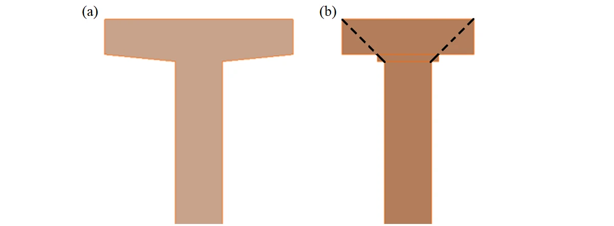
Fig. 13	   Width reduction of a cross-section: (a) user input; (b) FE model – automatically determined reduced width of a flange.

Fig. 11Width reduction of a cross-section: (a) user input; (b) FE model – automatically determined reduced flange width.\textsf{\textit{\footnotesize{Fig. 11\qquad Width reduction of a cross-section: (a) user input; (b) FE model – automatically determined reduced flange width.}}}Fig. 11Width reduction of a cross-section: (a) user input; (b) FE model – automatically determined reduced flange width.

In the case of haunches lying in the horizontal plane (Fig. 12), each haunch is divided into five sections along its length. Each of these sections is then modeled as a wall with a constant thickness, which is equal to the real thickness in the middle of the respective section.
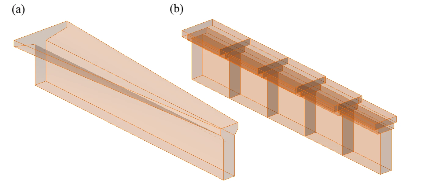
Fig. 14	Horizontal haunch: (a) user input; (b)  FE model – a haunch automatically divided into five sections.

Fig. 12Horizontal haunch: (a) user input; (b)  FE model – a haunch automatically divided into five sections.\textsf{\textit{\footnotesize{Fig. 12\qquad Horizontal haunch: (a) user input; (b)  FE model – a haunch automatically divided into five sections.}}}Fig. 12Horizontal haunch: (a) user input; (b)  FE model – a haunch automatically divided into five sections.

Related articles

Solution for walls and details of concrete structures
  • Concrete
  • Detail 2D
  • EN (Eurocode)
  • CSFM
  • SLS
  • Wall
  • ACI (USA)
  • +7
  • Concrete
  • Detail 2D
  • EN (Eurocode)
  • CSFM
  • SLS
  • Wall
  • ACI (USA)

Verifications

Solution for walls and details of concrete structures

Read more
Fire resistance check of concrete structures
  • Concrete
  • EN (Eurocode)
  • RCS
  • Fire resistance
  • +4
  • Concrete
  • EN (Eurocode)
  • RCS
  • Fire resistance

Webinar

Fire resistance check of concrete structures

Read more