ULS results in RCS - Capacity N-M-M, Shear, Torsion, Interaction, Response N-M-M
There are five tabs for ULS results in the application.
- Capacity N-M-M
- Shear
- Torsion
- Interaction
- Response N-M-M
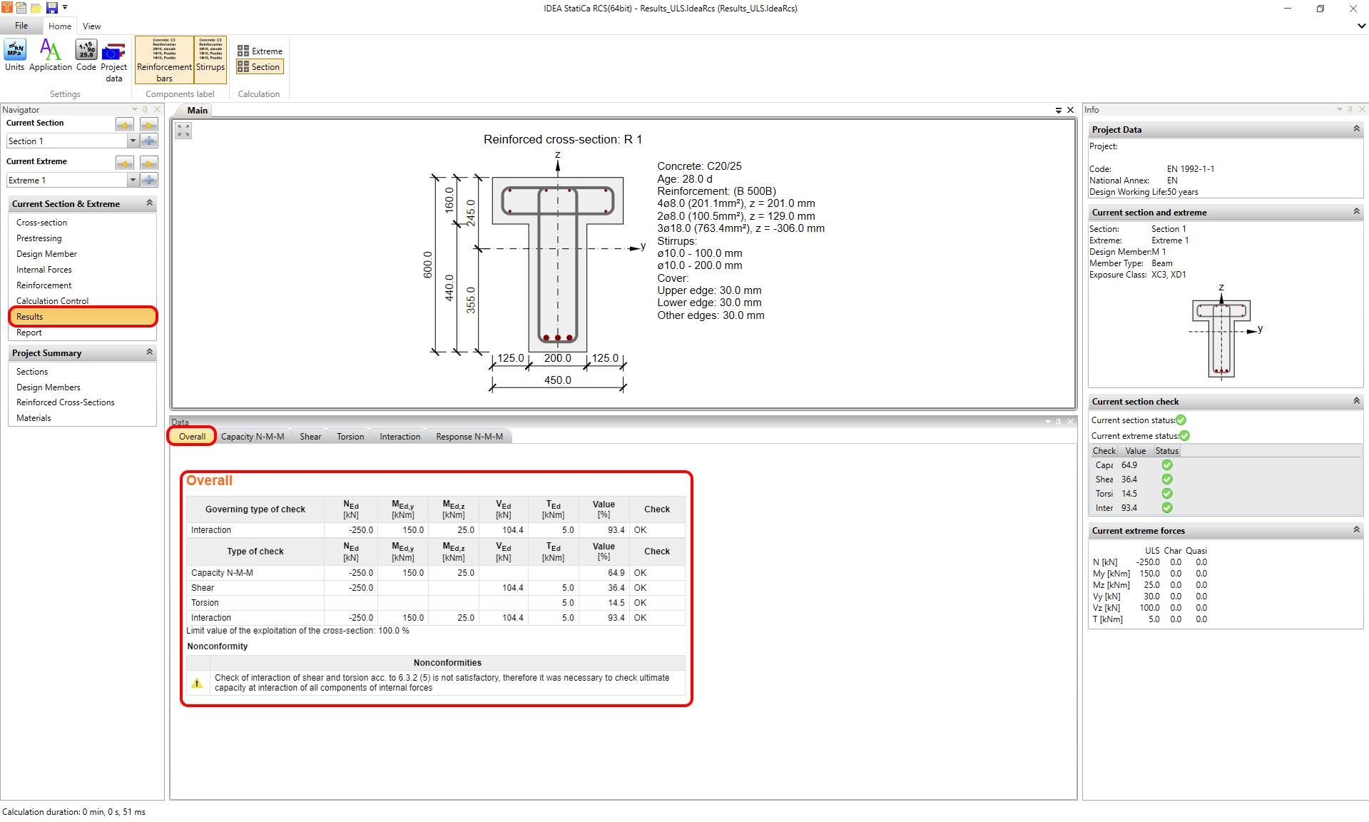
Before we go through them let's look at the Overall result where you can find all selected results (by using calculation control) with corresponding internal forces.
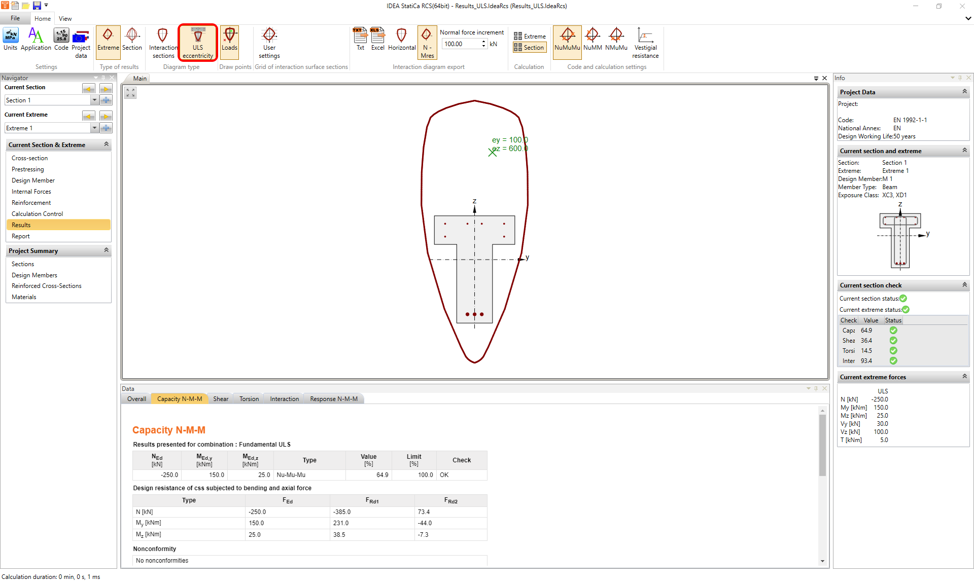
Capacity N-M-M
The first tab is the Capacity N-M-M check. This type of calculation provides a check of the interaction between normal force and bending moments. If you want to know the theory behind it, read this article: Bending.
As was written in the introduction. The article is focused on practical usage. So let's have a look at ways how to display this type of result. Listed below are three display settings that can be combined with each other.
- Diagram type
- Interaction sections
- ULS eccentricity
- Type of results
- for Extreme
- for Section
- Evaluation of interaction diagram
- NuMuMu
- NuMM
- NMuMu
Let's go over the options for combinations of display settings.
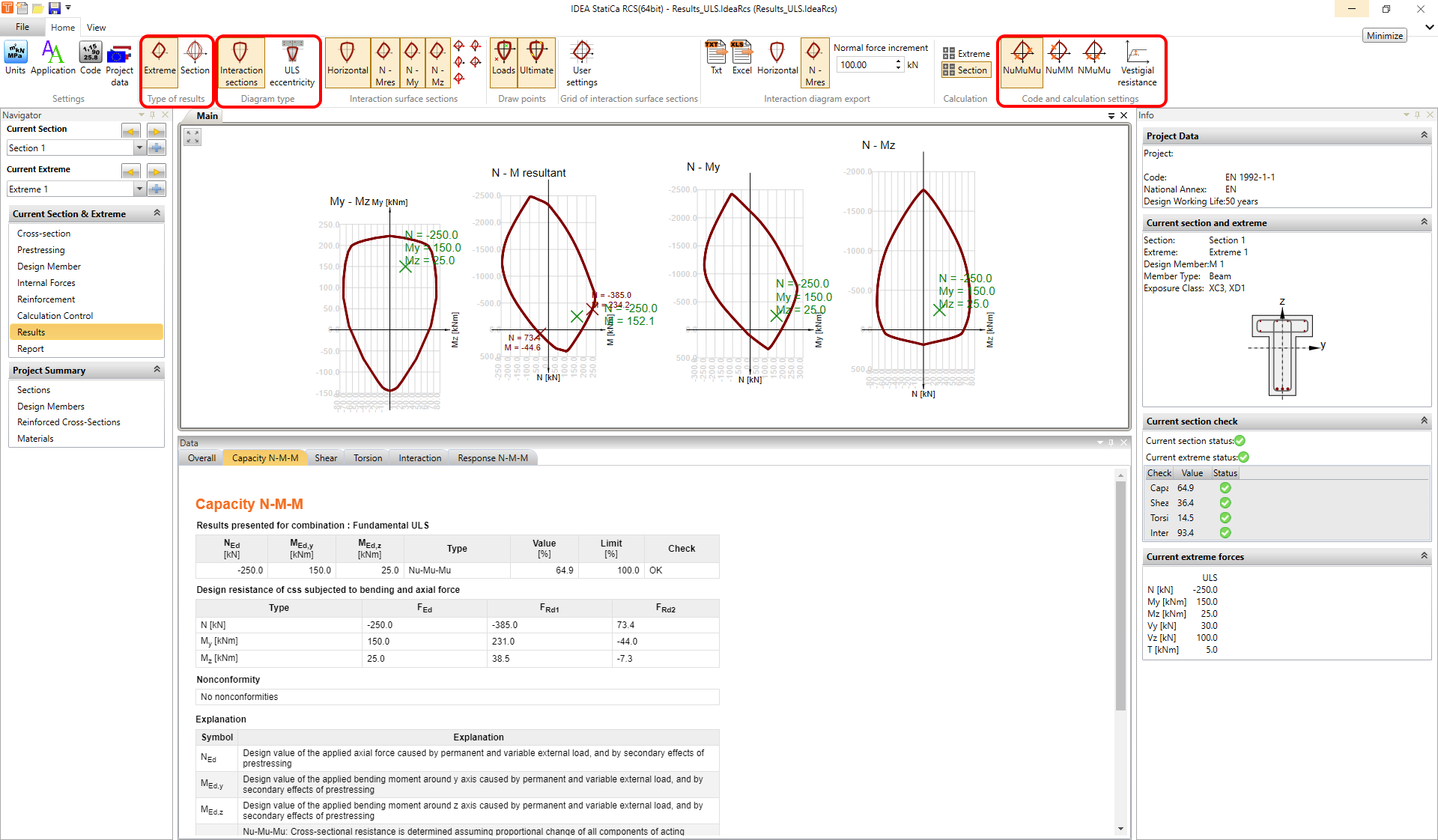
Interaction sections + Extreme
At first, we start with the Interaction sections displayed for the current extreme. In the toolbar Interaction surface section, you can display four sections of an interaction surface.
- My - Mz -> horizontal surface
- N - M resultant -> according to the current ratio between My and Mz
- N - My -> vertical surface on y-axis
- N - Mz -> vertical surface on z-axis
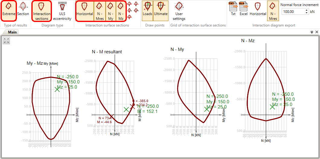
You can also decide if you want to see loads or the ultimate point in the diagram. It can be changed in the top ribbon in the Draw points toolbar.
In the Grid of interaction surface sections toolbar, you can adjust the grid of the interaction diagrams.
And the interaction diagrams can be also exported to the text file or to the spreadsheet. To do it use tools in the Interaction diagram export toolbar.
Evaluation of interaction diagram
There are three methods to evaluate interaction diagram.
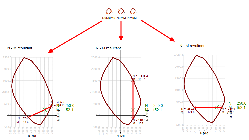
NuMuMu - cross-sectional resistance is determined assuming a proportional change of all components of acting internal forces.
NuMM - cross-sectional resistance is determined assuming constant bending moments.
NMuMu - cross-sectional resistance is determined assuming constant normal force.
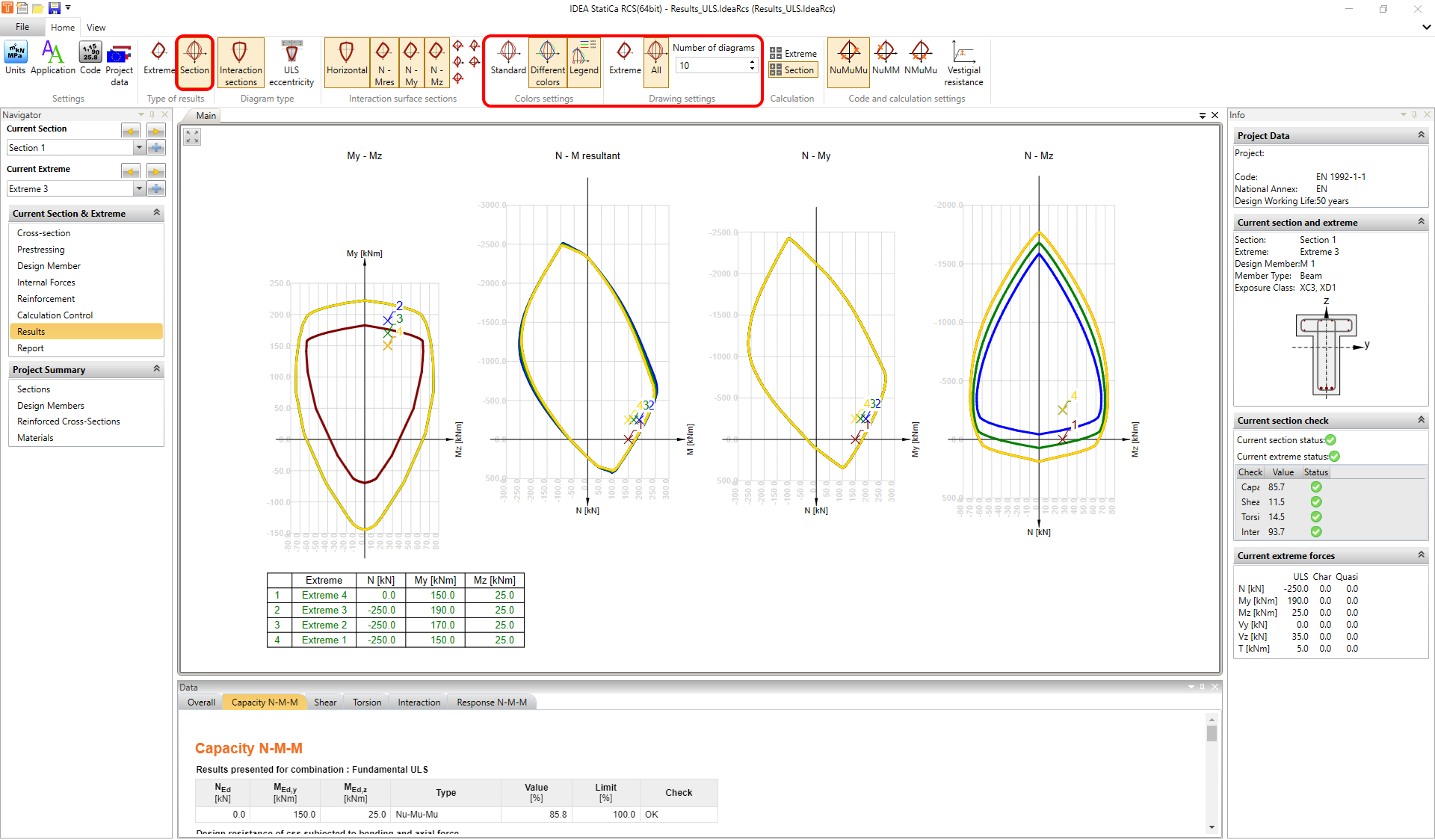
Interaction sections + Section
Secondly, we can display Interaction sections for more extremes. To do it simply change the Type of results in the top ribbon. You will then see all the extremes drawn to one (or more) interaction section. If the interaction sections differ for individual extremes, you can get the program to display them with different colours. It can be done in the top ribbon in the Colour settings toolbar. You can also limit the number of displayed diagrams in the Drawing settings toolbar.
ULS eccentricity
Finally, you can display the diagram of an eccentricity of normal force depending on normal forces. It can be again displayed for Extreme or for Section.
Shear
The second tab for ULS checks is the Shear. All of the calculations are done according to EN 1992-1-1 article 6.2. You can control the theta angle at the top ribbon. This angle governs the inclination between concrete struts and the beam axis perpendicular to the shear force. Or you can use the Strut optimization function, which can find the most effective angle automatically.
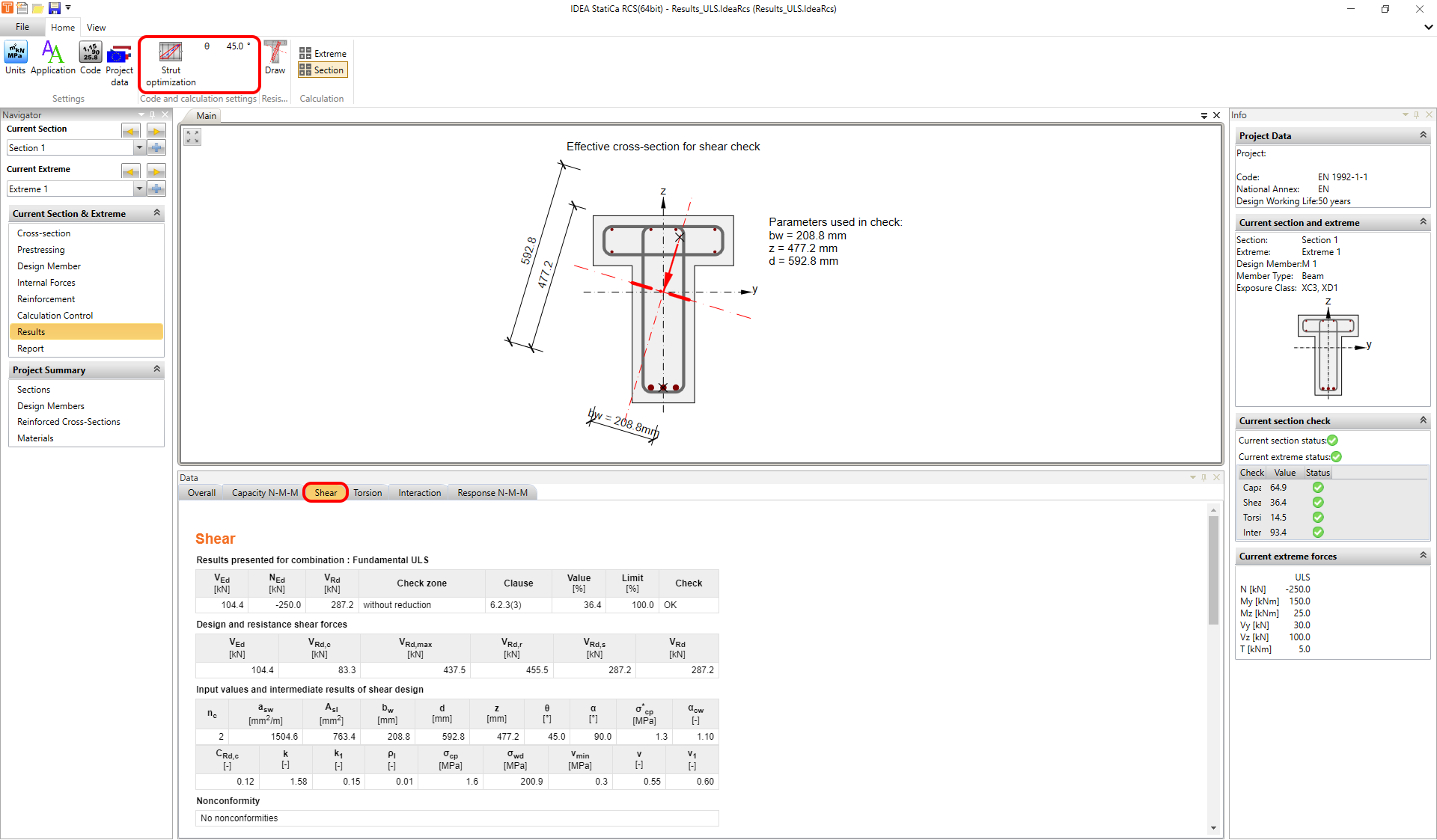
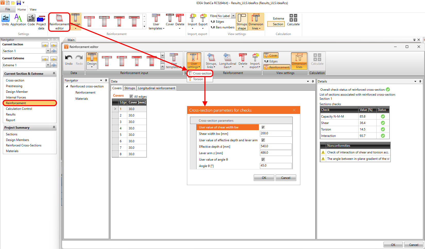
You can of course calculate the Shear capacity for both directions, but you have to be aware of the angle between the in-plane gradient of the strain plane and the resultant shear forces. The program can automatically calculate the effective depth of the cross-section d, inner lever arm z, and the effective width bw, but if the angle exceeds 20 degrees, the values of effective depth and lever arm and consequently strength in shear could be affected. So it is recommended to set these values manually in the Reinforcement editor -> User settings -> Cross-section.
- Read the following article to know - How to set the lever arm properly
If you want to know what is behind read the following article: Shear. In the Lever arm of internal forces chapter, you can find an explanation of why to set manually the values of effective depth and lever arm.
Another important topic is the evaluation of the shear in circular sections. Read the following article to learn how IDEA StatiCa RCS can solve such an issue - Shear in RCS - circular cross-sections
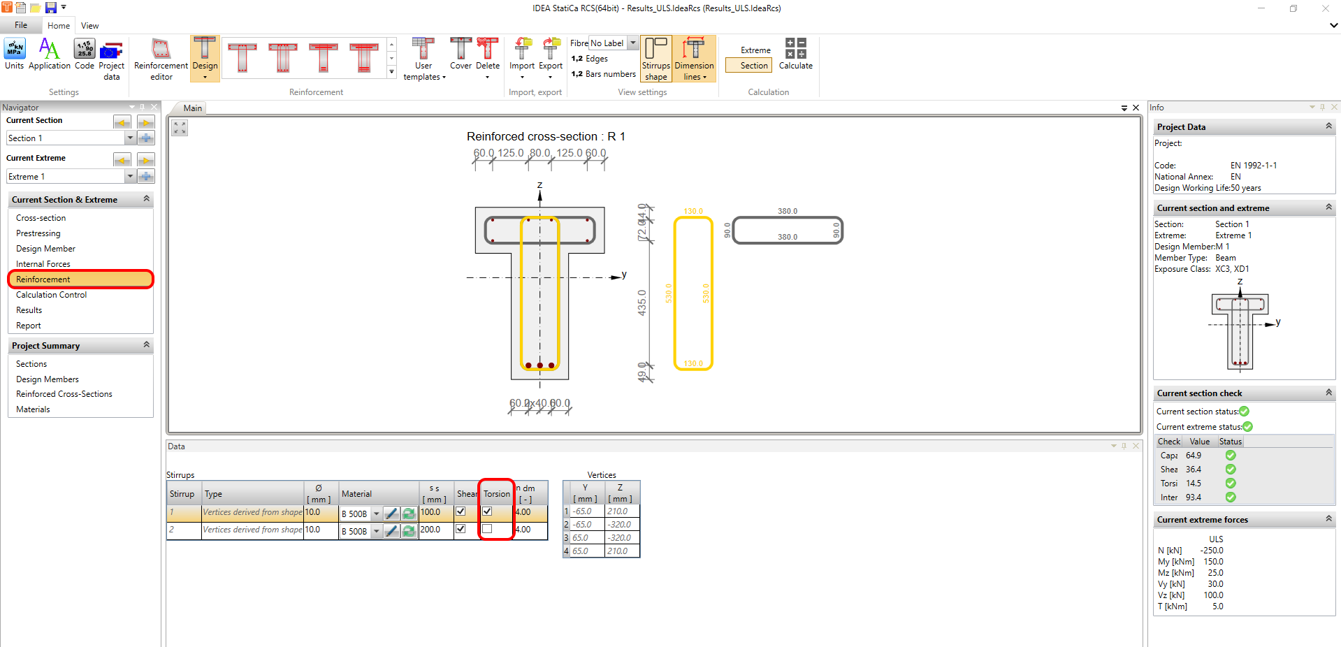
Torsion
The next tab for ULS checks is the Torsion. All of the calculations are done according to EN 1992-1-1 article 6.3. The theta angle is of course shared with the shear check and can be defined in the top ribbon as well as in the shear check.
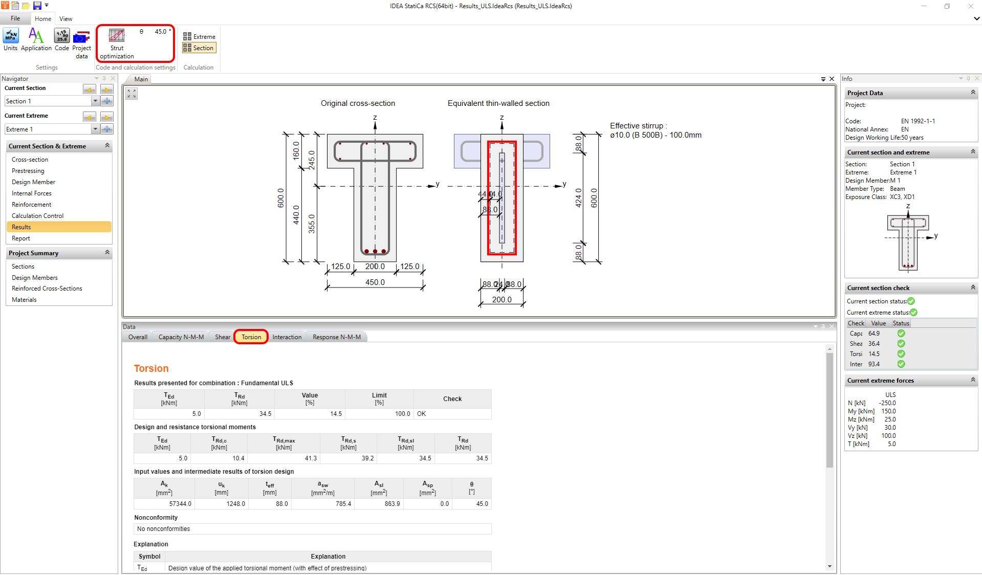
The equivalent thin-walled section can be created automatically based on the selected stirrup. If the situation is simple as in the following figure, there is no problem.
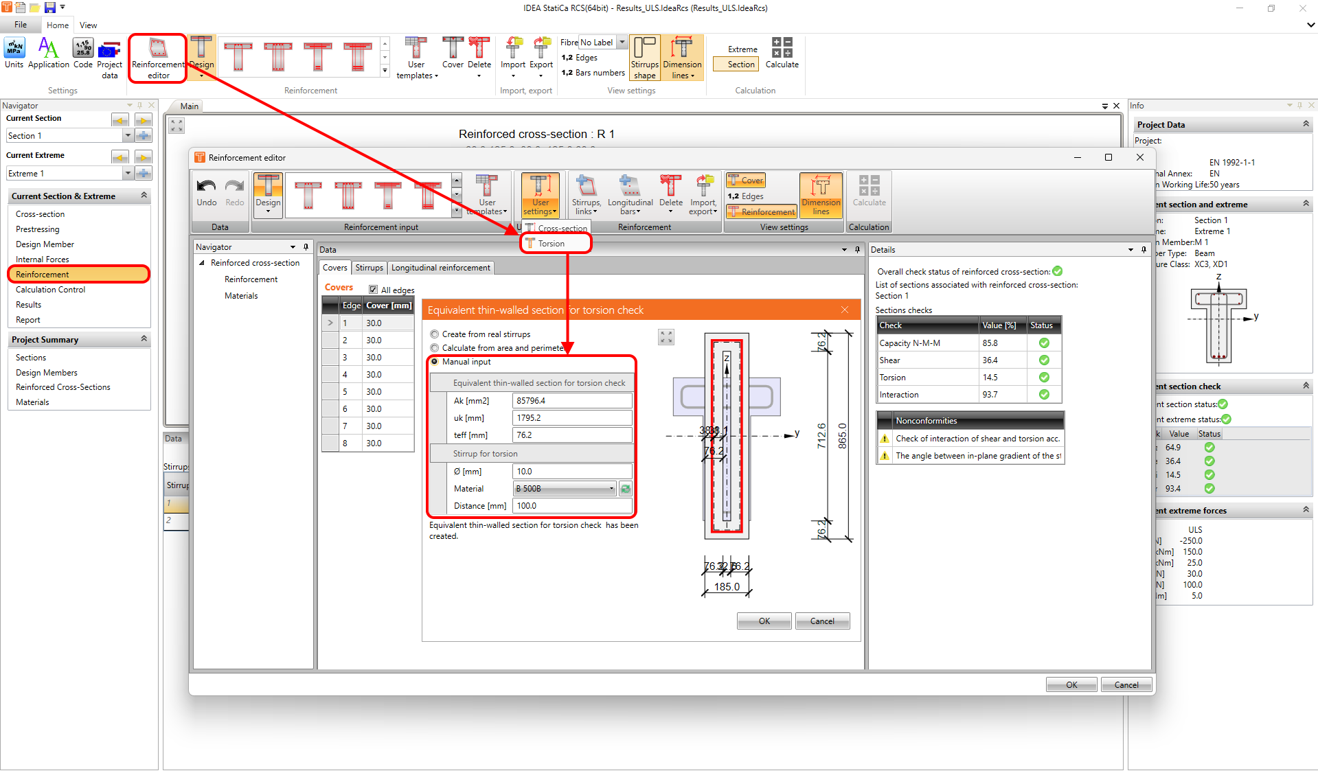
But in the case of complicated cross-sections like box girder bridges or general shapes, where multiple stirrups are usually defined for torsion, the automatic creation of the equivalent thin-walled section is not enough. In that case, go to Reinforcement editor -> User settings -> Torsion and do the manual input.
Again the theory behind the torsion calculation is described in the following article: Torsion.
Interaction
The interaction between shear force and torsion can be calculated as well as the interaction between shear torsion and bending. You can check concrete, shear reinforcement and longitudinal reinforcement. All theory about interaction is described in the following article: Interaction
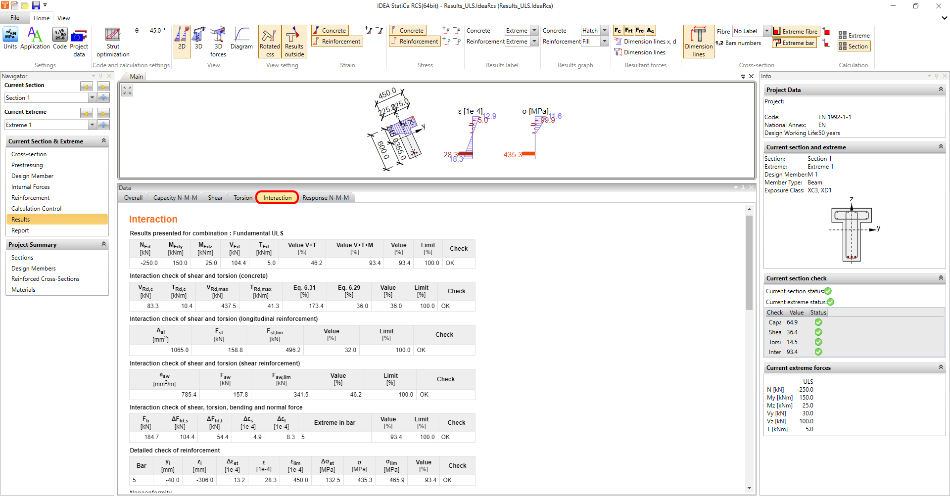
But the question is: Is it necessary to always check the interaction between all of the forces (V+T+M)? If not, where should I check what?
You have to check N-M-M capacity everywhere of course. But what about shear? Follow article 6.2.3 (5) from EN 1992-1-1 where you can read that you don't have to always use the full value of the shear force to check the shear reinforcement.
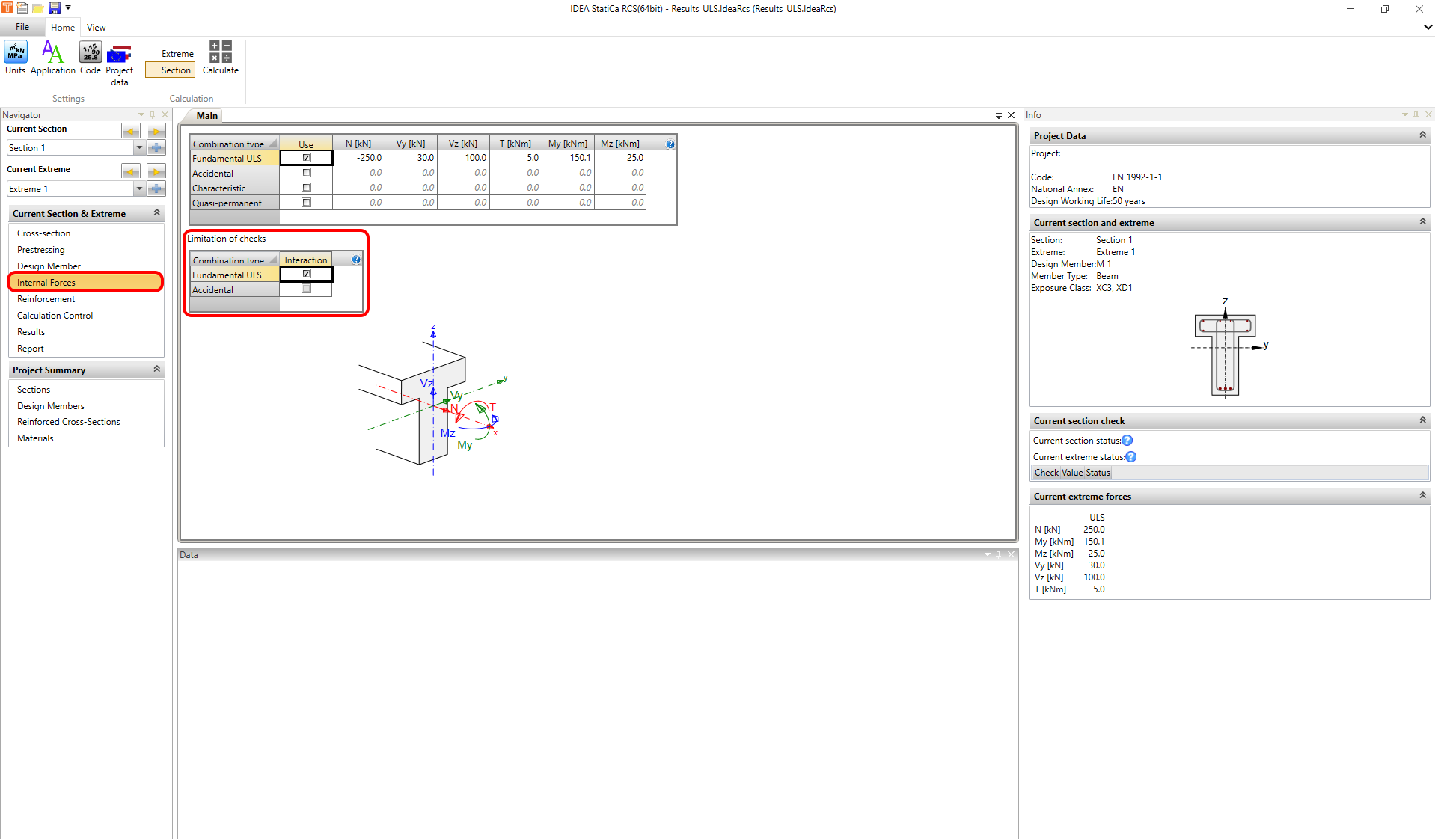
For longitudinal reinforcement above support, the entire interaction is not always necessary as well. To learn more read article 6.2.3 (7) from EN 1992-1-1. To exclude the additional tensile force in the longitudinal reinforcement due to shear go to Navigator -> Design member and turn on Limited interaction check.
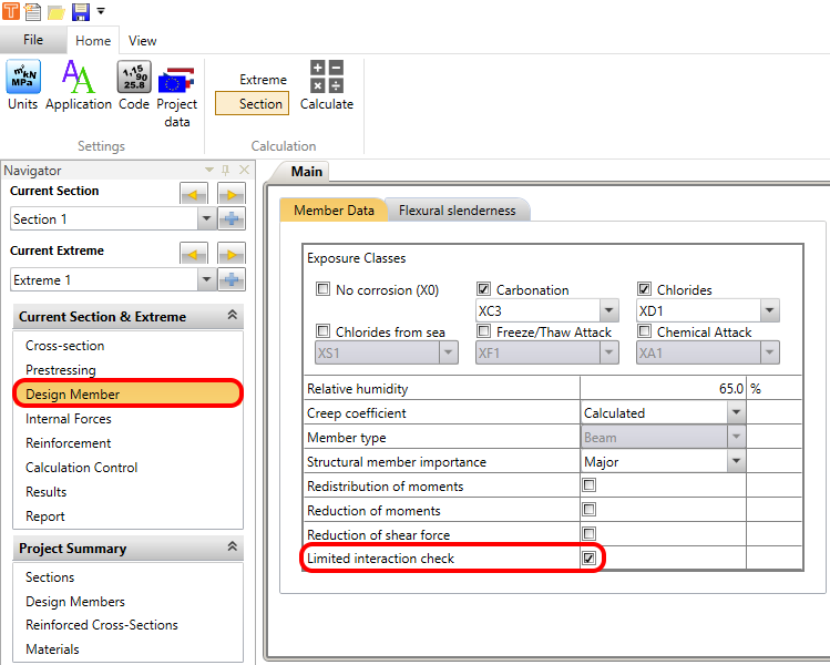
After that, you still have to choose the combination for the limited interaction check. It can be done in Navigator -> Internal forces.
Read the following article where you can find how the longitudinal force caused by shear and torsion is applied to the cross-section.
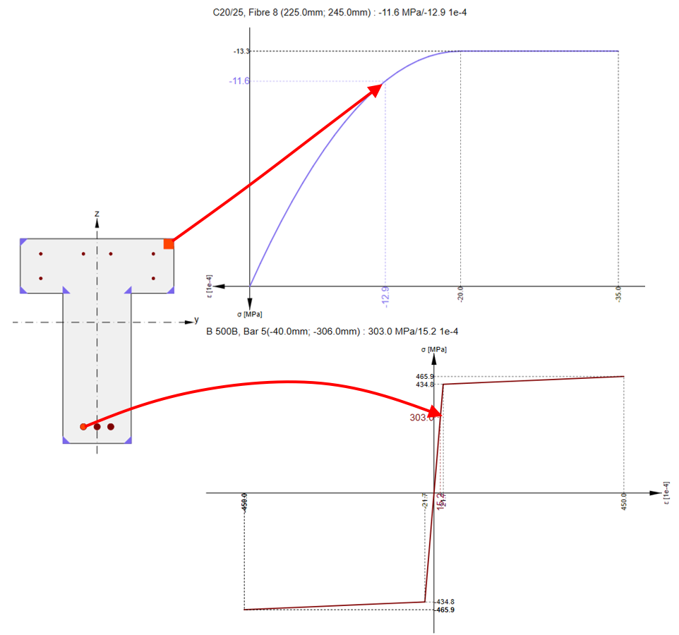
Response N-M-M
This type of calculation can find the response of the cross-section when the load is applied. The results (stress and strain) are then compared with the limits determined by the ultimate limit strain method.
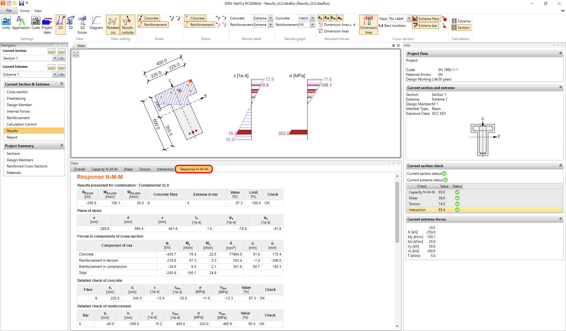
There are four different options for displaying results. Note that they are the same for Interaction.
- 2D
- 3D
- 3D forces
- Diagram
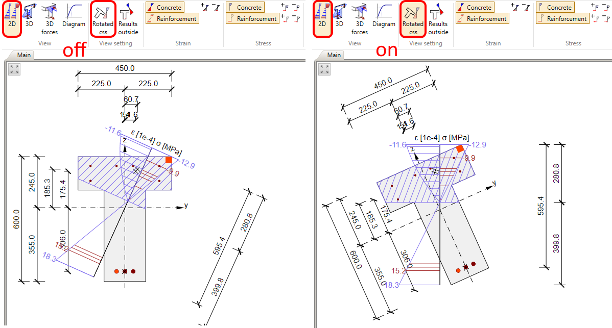
You can switch between them on the top ribbon. In the previous figure, the 2D displaying option was shown. If the option is selected, you can display a rotated cross-section or rotated results.
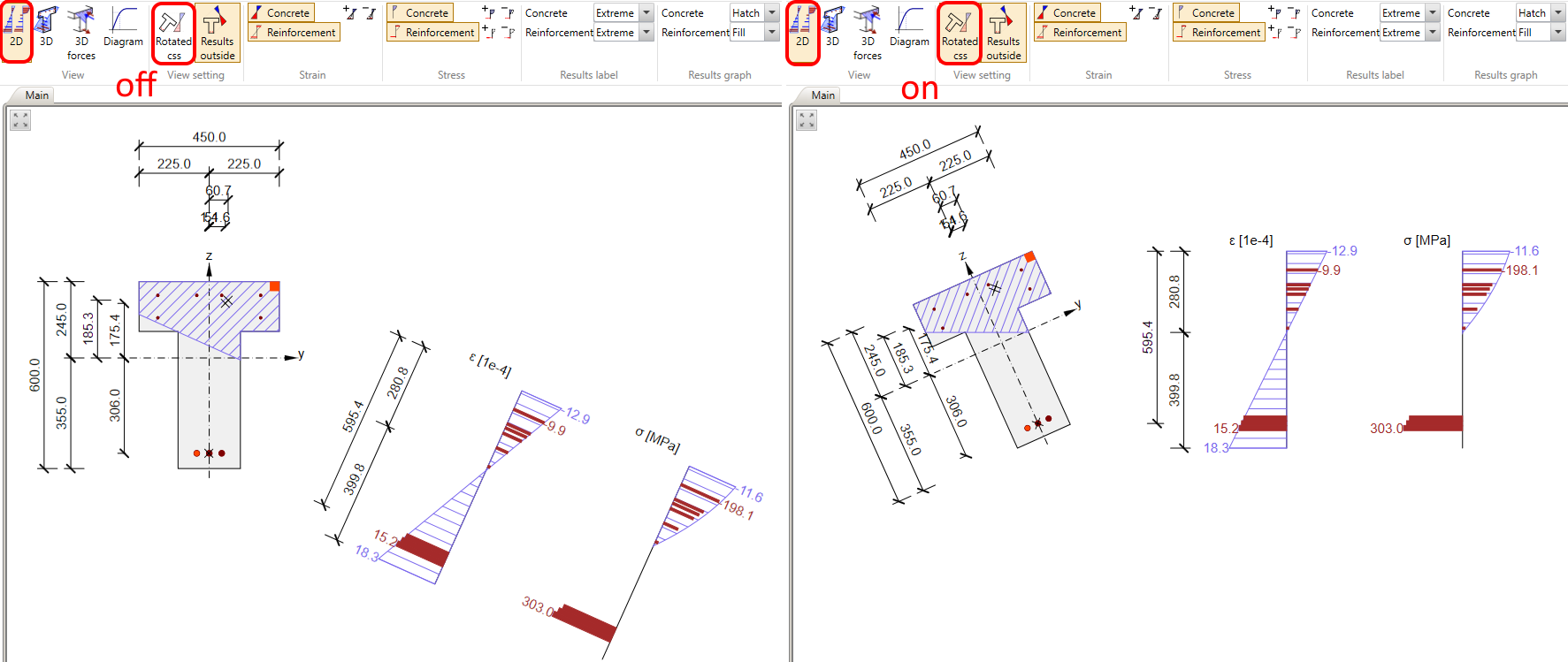
In the figure, the results were outside of the cross-section. If you need, the results can be also shown inside the section.
For the 2D view, you can turn off / on strain and stress in concrete and reinforcement, adjust the labels, modify the results graph, add dimension lines, and bar numbers, and display extreme fibre or extreme bar. All of these view settings are available in the top ribbon in the different toolbars.

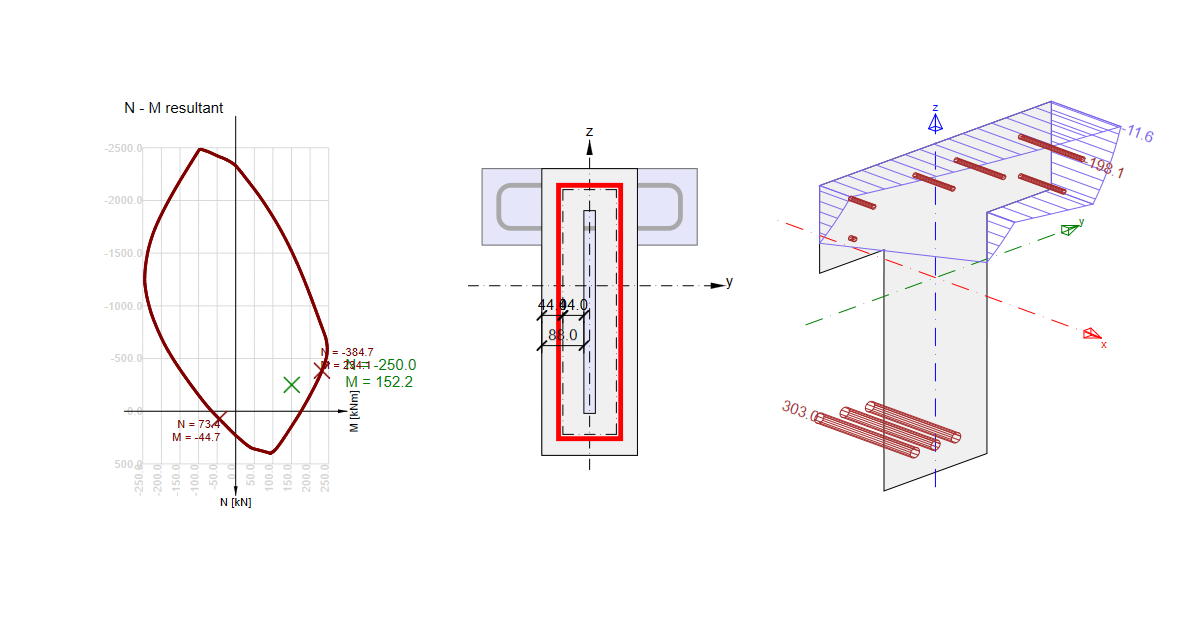
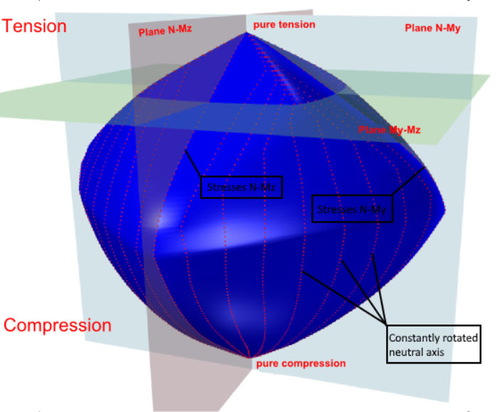
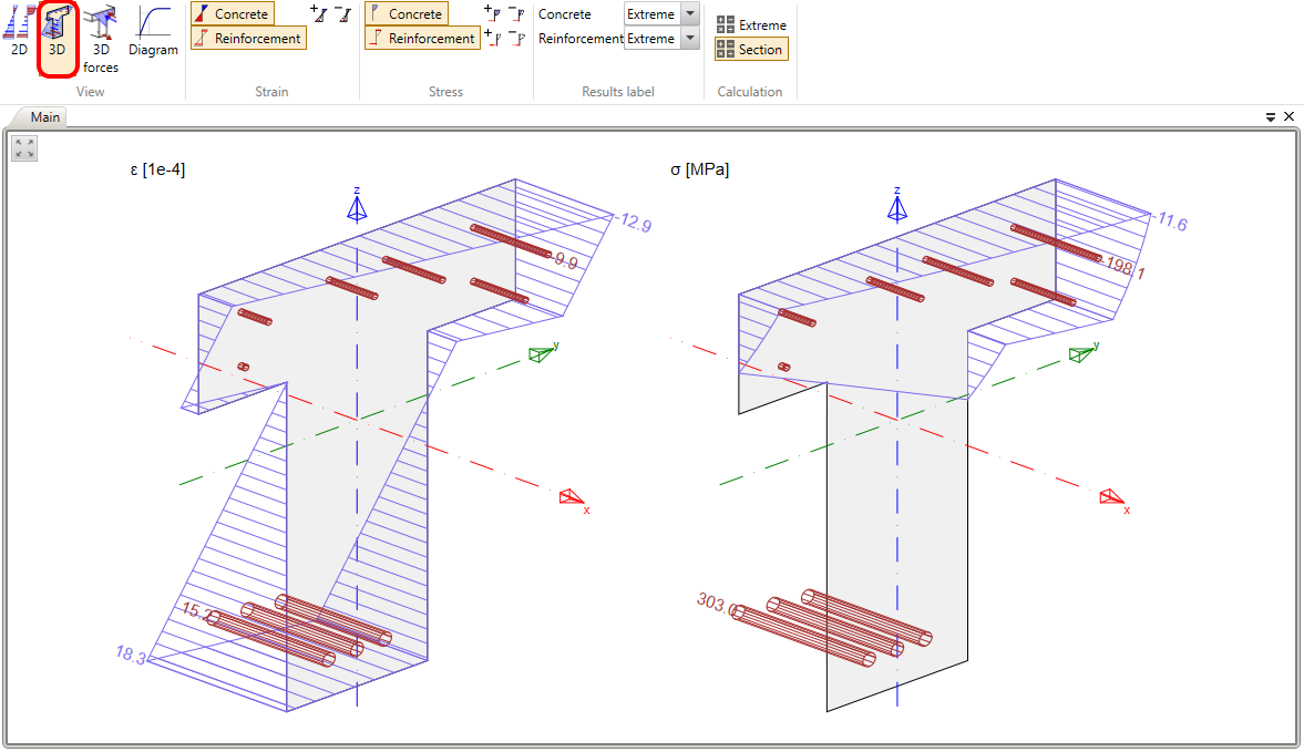
The 3D view is shown below. It can help you to understand the results of the cross-section affected by both bending moments My and Mz.
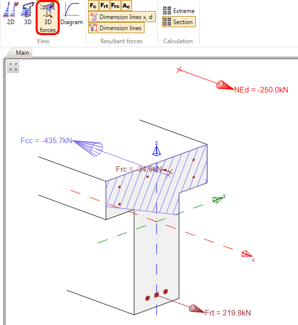
In 3D forces view, you can display the resultant forces for concrete in compression and reinforcement under the tension as well as under the compression. The normal force on eccentricity is also shown.
The last type of view is the Diagram. Here you can display the stress-strain diagram for each reinforcement bar and for each fibre in concrete.