Interaction of shear force and torsion for shear reinforcement
Determination of the force in shear reinforcement due to shear force.
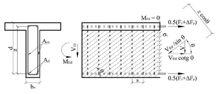
The calculation is based on the formula for calculating the resistance of the shear reinforcement defined in EN 1992-1-1. Based on equation 6.13 (chap. 6.2.3 (4)) the load-bearing resistance of one stirrup leg can be derived as:
\[{{V}_{Rd,s}}=\frac{{{A}_{sw,V}}}{s}z{{f}_{ywd}}\left( \cot \theta +\cot \alpha \right)\sin \alpha \cos \beta \]
\[\frac{{{A}_{sw,V}}}{s}={{a}_{sw,V}}\]
Asw,V . . . cross-sectional area of one stirrup leg resisting shear in considered section
s . . . . . spacing of the shear reinforcement in the direction of the longitudinal member axis
asw,V . . . cross-sectional area of the shear reinforcement per unit length
z . . . . . the inner lever arm. For a member with constant depth, corresponding to the bending moment in the element under consideration. In the shear analysis of reinforced concrete without axial force, the approximate value z = 0,9d may normally be used.
fywd . . . the design yield strength of shear reinforcement
θ . . . . . the angle between the concrete compression strut and the member axis perpendicular to the shear force
α . . . . . the angle between shear reinforcement and the member axis perpendicular to the shear force
β . . . . . inclination of the leg of the stirrup relative to the resultant of the applied shearing force
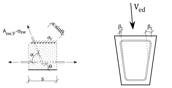
The shear force is redistributed evenly among the individual reinforcement resisting the shear force based on the angle of the reinforcement and the axial stiffness of the individual stirrup legs.
\[{{V}_{ed}}={{V}_{ed,1}}+{{V}_{ed,2}}+...+{{V}_{ed,n}}\]
\[{{V}_{ed}}={{\varepsilon }_{sw,V}}\cdot z\cdot \sum\limits_{i=1}^{{{n}_{V}}}{{{a}_{sw,i,V}}\cdot {{E}_{sw,i,V}}\cdot \left( \cot \theta +\cot {{\alpha }_{i}} \right)\cdot {{\cos }^{2}}{{\beta }_{i}}}\]
Further, the average reinforcement strain considered in the direction of the resultant shear force can be derived:
\[{{\varepsilon }_{sw,V}}=\frac{{{V}_{ed}}}{z\cdot \sum\limits_{i=1}^{{{n}_{V}}}{{{a}_{sw,i,V}}\cdot {{E}_{sw,i,V}}\cdot \left( \cot \theta +\cot {{\alpha }_{i}} \right)\cdot {{\cos }^{2}}{{\beta }_{i}}}}\]
The actual strain of the i-th reinforcement can be calculated as:
\[{{\varepsilon }_{sw,i,V}}=\frac{{{\varepsilon }_{sw,V}}}{\sin {{\alpha }_{i}}}\cdot \cos {{\beta }_{i}}\]
The tension in a given leg of the reinforcement:
\[{{\sigma }_{sw,i,V}}={{\varepsilon }_{sw,i,V}}\cdot {{E}_{si,V}}\]
Determination of the force in individual stirrup due to torsion
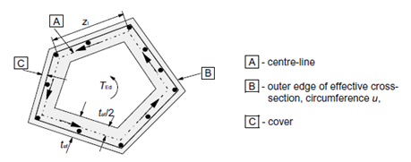
The torsional resistance of a section may be calculated on the basis of a thin-walled closed section, in which equilibrium is satisfied by a closed shear flow. Solid sections may be modeled by equivalent thin-walled sections. For non-solid sections, the equivalent wall thickness should not exceed the actual wall thickness.
Shear flow in the walls of a thin-walled closed section due to torsion may be calculated as:
\[{{\tau }_{t}}\cdot {{t}_{ef}}=\frac{{{T}_{ed}}}{2{{A}_{k}}}\]
Shear force in a particular wall is then:
\[{{V}_{i}}={{\tau }_{t}}\cdot {{t}_{ef}}\cdot {{l}_{i}}\]
li . . . . length of the centreline of the wall under consideration
Shear force in the web - the length of the web centreline can be substituted by the value of the lever arm "z".
\[{{V}_{ed,T}}=\frac{{{T}_{ed}}}{2{{A}_{k}}}\cdot z\]
Force in stirrups resisting torsion per one meter of the member length (per unit length):
\[{{F}_{sw,T}}=\frac{{{V}_{ed,T}}}{z\cdot \cot \theta }=\frac{{{T}_{ed}}}{2{{A}_{k}}}\cdot tg\theta\]
Decompositions of forces for individual stirrup
If the same material is defined for all stirrups, the resulting stress due to torsion in each stirrup leg is constant. Then:
\[{{\sigma }_{sw,T}}=\frac{{{F}_{sw,T}}}{{{a}_{sw,T}}}\]
where asw,T is the total area of stirrups resisting the torsion per unit length.
In the case that individual stirrups have different materials, the axial stiffness of the individual bars must be taken into account.
\[{{F}_{sw,T}}={{F}_{s1,T}}+{{F}_{s2,T}}+{{F}_{s3,T}}+...+{{F}_{sn,T}}=\sum\limits_{i=1}^{{{n}_{T}}}{{{F}_{si,T}}}\]
\[{{\varepsilon }_{sw,T}}=\frac{{{F}_{sw,T}}}{\sum\limits_{i=1}^{{{n}_{T}}}{\left( {{a}_{si,T}}\cdot {{E}_{si,T}} \right)}}\]
nT . . . . number of legs of reinforcement (groups of reinforcement) resisting torsion
Fsi,T . . . force in the i-th group of reinforcement resulting from torsion per unit length
asi,T . . . cross-sectional area of the shear reinforcement resisting torsion per unit length
Esi,T . . . Young´s modulus of elasticity of the i-th group of reinforcement resisting torsion
εsw,T . . strain in the reinforcement due to torsion
The resulting stress in each stirrup due to applied torsion is calculated as:
\[{{\sigma }_{sw,i,T}}={{\varepsilon }_{sw,T}}\cdot {{E}_{si,T}}\]
V+T interaction
The calculation of the stresses in stirrups due to shear and torsion is then a summation of the stresses due to individual load components.
\[{{\sigma }_{sw,i}}={{\sigma }_{sw,i,V}}+{{\sigma }_{sw,i,T}}\]
Resulting force in the i-th reinforcement:
\[{{F}_{sw,i}}={{a}_{sw,i}}\cdot {{\sigma }_{sw,i}}\]
Interaction of shear, torsion and bending for longitudinal reinforcement
Determination of the force in each longitudinal reinforcement due to the normal force and bending moment
The application RCS is used to calculate the cross-sectional response due to the combination of the normal force and bending moment to determine the stress and strain in the individual longitudinal bars and prestressing reinforcement.
Determination of the force in the individual longitudinal reinforcement due to shear force
The increment of the tensile force in the longitudinal reinforcement ΔFtd from the shear force depends on the geometry of the strut and tie model.
\[\Delta {{F}_{td}}={{V}_{ed}}\left( \cot \theta -\cot \alpha \right)\]
ΔFtd . . . increment of tensile force in the longitudinal reinforcement due to the shear force
Ved . . . . design value of the shear force acting in the section under consideration
θ . . . . . the angle between the concrete compression strut and the member axis
α . . . . . the angle between shear reinforcement and the member axis
For the longitudinal reinforcement located in the tension chord, the resulting force Ft in the longitudinal reinforcement due to the combination N+M+V should be taken not greater than MEd,max/z (where MEd,max is the maximum moment along the beam)
\[{{F}_{t}}=\frac{{{M}_{Ed}}}{z}+0,5{{V}_{ed}}\left( \cot \theta -\cot \alpha \right)\le \frac{{{M}_{Ed,\max }}}{z}\]
The force ΔFtd is transmitted by all bonded prestressing tendons and reinforcement located in the part of the cross-section that resists shear (the web in the case of an I-profile). On the safe side, the contribution of prestressing reinforcement can be considered 0. The assumption of the calculation is that the increment of the axial strain of the individual longitudinal reinforcement resisting shear is constant (Δεs1,V = Δεs2,V = .... =Δεp1,V = Δεp2,V = ... = ΔεV = const.). The derivation is valid for a bilinear reinforcement working diagram with a horizontal plastic branch. In the case of a diagram with an inclined branch, the calculation must be modified.
\[\Delta {{F}_{td}}=\Delta {{F}_{s}}+\Delta {{F}_{s}}\]
\[\Delta {{F}_{td}}=\Delta {{\varepsilon }_{V}}\cdot \sum\limits_{i=1}^{{{n}_{s,V}}}{{{A}_{sl,i,V}}\cdot {{E}_{sl,i,V}}}+\Delta {{\varepsilon }_{V}}\cdot \sum\limits_{i=1}^{{{n}_{p,V}}}{{{A}_{pl,i,V}}\cdot {{E}_{pl,i,V}}}\]
ΔεV . . . . strain increment in the longitudinal reinforcement due to the shear force
ns,V . . . . number of longitudinal reinforcements resisting the shear force
Asl,i,V . . . area of the i-th longitudinal reinforcement resisting the shear force
Esl,i,V . . . Young´s modulus of elasticity of the i-th longitudinal reinforcement resisting the shear force
np,V . . . . number of tendons resisting the shear force
Apl,i,V . . . area of the i-th tendon resisting the shear force
Epl,i,V . . . Young´s modulus of elasticity of the i-th tendon resisting the shear force
After determining the value of force ΔFtd, the average reinforcement strain ΔεV can then be calculated.
\[\Delta {{\varepsilon }_{V}}=\frac{\Delta {{F}_{td}}}{\sum\limits_{i=1}^{{{n}_{s,V}}}{{{A}_{sl,i,V}}\cdot {{E}_{sl,i,V}}}+\sum\limits_{i=1}^{{{n}_{p,V}}}{{{A}_{pl,i,V}}\cdot {{E}_{pl,i,V}}}}\]
Stress increment in the individual longitudinal bars due to the applied shear force:
for rebar \[\Delta {{\sigma }_{sl,i,V}}=\Delta {{\varepsilon }_{V}}\cdot {{E}_{sl,i,V}}\]
for tendon \[\Delta {{\sigma }_{pl,i,V}}=\Delta {{\varepsilon }_{V}}\cdot {{E}_{pl,i,V}}\]
Determination of the force in each longitudinal reinforcement from torsion
It is very important to determine the longitudinal reinforcement that resist the torsion. These are the reinforcement that are located in a torsion-resisting alternate effective thin-walled cross-section.
\[\frac{\sum{{{A}_{sl}}{{f}_{yd}}}}{{{u}_{k}}}=\frac{{{T}_{ed}}}{2{{A}_{k}}}\cot \theta \]
According to EN 1992-1-1, several conditions must be fulfilled for longitudinal torsion resistant reinforcement:
- the reinforcement should be uniformly distributed along the length zi, but in small cross-sections the reinforcement may be concentrated at the corners of the stirrup
- the maximum axial distance of the longitudinal reinforcement is 350 mm
The contribution of prestressing reinforcement is not considered according to EN 1992-1-1.
The code EN 1992-2 states that the contribution of prestressing reinforcement may be considered, but the maximum stress increment in the prestressing reinforcement shall not exceed Δσp ≤ 500MPa. Then the formula can be modified:
\[\frac{\sum{{{A}_{sl}}{{f}_{yd}}+\sum{{{A}_{p}}\Delta {{\sigma }_{p}}}}}{{{u}_{k}}}=\frac{{{T}_{ed}}}{2{{A}_{k}}}\cot \theta\]
However, since the increment of prestressing reinforcement can be considered, but it is at the user's choice. Currently, prestressing reinforcement is not considered in the calculation.
The assumption of the calculation is that the increment of the axial strain of each longitudinal shear resisting reinforcement is constant (Δεs1,T = Δεs2,T = .... =Δεp1,T = Δεp2,T = ... = ΔεT = const.). The derivation is valid for a bilinear reinforcement working diagram with a horizontal plastic branch. In the case of a diagram with an increasing branch, the calculation must be modified.
\[\frac{\sum\limits_{i=1}^{{{n}_{T}}}{{{A}_{sl,i,T}}\cdot \Delta {{\sigma }_{s,i,T}}}}{{{u}_{k}}}=\frac{{{T}_{ed}}}{2{{A}_{k}}}\cot \theta\]
\[\frac{\sum\limits_{i=1}^{{{n}_{T}}}{{{A}_{sl,i,T}}\cdot \Delta {{\varepsilon }_{T}}\cdot {{E}_{s,i,T}}}}{{{u}_{k}}}=\frac{{{T}_{ed}}}{2{{A}_{k}}}\cot \theta\]
\[\Delta {{\varepsilon }_{T}}=\frac{{{T}_{ed}}\cdot {{u}_{k}}}{2{{A}_{k}}\cdot \sum\limits_{i=1}^{{{n}_{T}}}{{{A}_{sl,i,T}}\cdot {{E}_{s,i,T}}}}\cot \theta\]
Ted . . . . the design value of the torque applied in the section under consideration
θ . . . . . inclination of the compression diagonals with respect to the longitudinal axis of the beam (identical to that for the shear force)
uk . . . . perimeter of the area Ak
Af . . . . the area defined by the centreline of the replacement hollow thin-walled section
ns,T . . . .number of longitudinal concrete reinforcement resisting torque
Asl,i,T . . . area of the i-th longitudinal concrete reinforcement resisting torque
ΔεT . . . .the change in the longitudinal reinforcement transformation due to the torque
Δσs,i,T . . change in stress in the i-th longitudinal reinforcement due to torque
Esl,i,T . . . modulus of elasticity of the i-th longitudinal concrete reinforcement resisting the torque
Stress increment in each longitudinal reinforcement from the applied torque:
\[\Delta {{\sigma }_{sl,i,T}}=\Delta {{\varepsilon }_{T}}\cdot {{E}_{sl,i,T}}\]