With respect to fragile failure the shear check is one of the important checks of a reinforced concrete section.
Calculation procedure
Calculation of shear resistance is composed of several basic parts. At first we should analyze whether cracks due to bending occur or not in the checked location. If any, use the calculation according to EN 1992-1-1 [2], Article 6.2.2 (1). Otherwise, we determine whether it is plane concrete or poorly reinforced concrete, then proceed in accordance with EN 1992-1-1 Article 12.6.3.
For reinforced uncracked concrete (without shear reinforcement) we check according to EN 1992-1-1 Article 6.2.2 (2). For Elements, where is required shear reinforcement we check according to Article 6.2.3 [2].
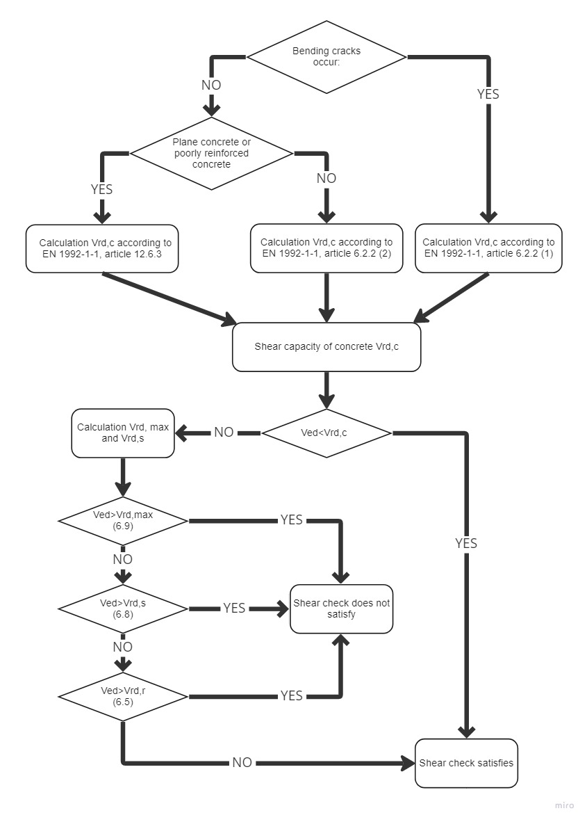
\[ \textsf{\textit{\footnotesize{\qquad Process diagram for shear check.}}}\]
Shear resistance of members without shear reinforcement
Shear resistance of members in cracked bending zones (art. 6.2.2 (1) [2])
Shear resistance of reinforced concrete members without shear reinforcement subject to bending moment is given by:
\[{{V}_{Rd,cm}}=~{{C}_{Rd.c}}k~{{\left( 100~{{\varrho }_{l}}{{f}_{ck}} \right)}^{{}^{1}/{}_{3}}}~{{b}_{w}}d\]
Which was defined on the base of tests executed on a representative number of simple beams in case of failure by shear force. Since the above resistance may be zero for elements without longitudinal reinforcement (rl), for poorly reinforced members was derived equations. Since the above resistance may be zero for members without longitudinal reinforcement (rl), for the poorly reinforced members was determined by equation
\[{{V}_{Rd,c}}\ge ~{{\upsilon }_{min}}{{b}_{w}}d\]
For shear resistance with influence of normal force was determined by equation
\[{{V}_{Rd,cn}}=~{{k}_{1}}{{\sigma }_{cp}}~{{b}_{w}}d\]
Shear resistance in its complete expression which is corresponding with EN 1992-1-1 art. 6.2.2 (1)
\[{{V}_{Rd,c}}=~\left[ {{C}_{Rd.c}}k~{{\left( 100~{{\varrho }_{l}}{{f}_{ck}} \right)}^{{}^{1}/{}_{3}}}+{{k}_{1}}{{\sigma }_{cp}} \right]~{{b}_{w}}d\]
With minimum of
\[{{V}_{Rd,c}}=~\left( {{\upsilon }_{min}}+{{k}_{1}}{{\sigma }_{cp}} \right){{b}_{w}}d\]
where
CRd,c = 0,18 / γc,
k cross-section height factor
\[k=1+\sqrt{\frac{200}{d}}<2,0\]
ρ1 reinforcement ratio for longitudinal reinforcement
\[{{\varrho }_{l}}=\frac{{{A}_{sl}}}{{{b}_{w}}d}\le 0,02\]
fck characteristic compressive cylinder strength of concrete at 28 days
k1 = 0,15
σcp = NEd / Ac < 0,2 fcd v MPa
bw smallest width of the cross-section in the tensile area
d effective depth of a cross-section
υmin minimal equivalent shear strength υmin = 0.035 k3/2 fck1/2
Shear resistance of members in uncracked bending zones (art. 6.2.2 (2) [2])
Shear resistance of members in uncracked bending zones can be determined from the Mohr circle. Into equation
\[{{\sigma }_{1,2}}=\frac{{{\sigma }_{x}}+{{\sigma }_{y}}}{2}\pm \sqrt{{{\left( \frac{{{\sigma }_{x}}-{{\sigma }_{y}}}{2} \right)}^{2}}+\tau _{z}^{2}}\]
We substitute σx = σcp a τz = VRd,c S / (I bw) and figure out VRd,c and get equation corresponding with formula given in EN 1992-1-1 art. 6.2.2 (2)
where
I is the second moment of area,
bw is the width of the cross-section at the centroidal axis
S is the first moment of area above and about the centroidal axis,
fctd design axial tensile strength of concrete in MPa,
scp is the concrete compressive stress at the centroidal axis due to loading and/or prestressing,
al transmission length factor, usually 1,0.
In relation with the above it should be noted that in areas without bending cracks the resistance VRd ,c can be significantly higher than in cracked areas according to Article 6.2.2 (1) [2]. The figure below clearly shows that although the shear force is checked at its extreme (which does not produce cracks), need not necessarily ensure that it will be transferred along the whole beam length. It is due to a change in the method of calculating the shear resistance of the concrete. On the safe side, of course, the shear resistance can be considered according to Article 6.2.2 (1) [2] also in places where cracks will not occur.
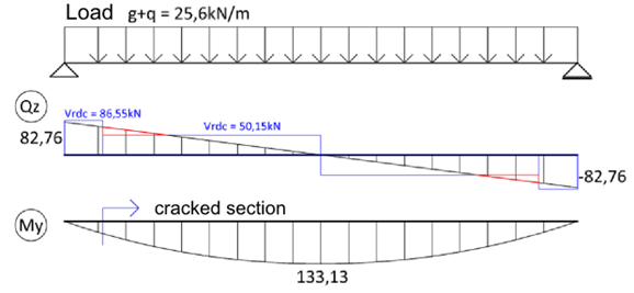
\[ \textsf{\textit{\footnotesize{\qquad Shear resistance comparison before and after the cracks occurred.}}}\]
To the expression of VRd, c according to Article 6.2.2 (2)[2] it must also be noted that in the general case should be based on check at the fiber of the extreme principal concrete tensile stress in the zone of normal compressive stress, but not at the center of gravity of the section. At this point it is necessary to calculate the cross-sectional characteristics (S and bW). To determine the maximum principal stress s1 in program IDEA RCS we draw a line through the centre of gravity in the direction of the resultant shear forces. This line we divide to 20 sectors. On this line we will present more characteristic points (points of the cross-section polygon, centre of gravity, the neutral axis). Within these points, we calculate S, bw, σx, τyz a σ1. At the point of maximum principal tensile stress we will calculate the shear resistance.
Shear force before applying the reduction factor b required by Article 6.2.2 (6) must satisfy the extra condition
\[ {{V}_{Ed}}\le 0,5~{{b}_{w}}d~\upsilon ~{{f}_{cd}}\]
where
\[ {{ υ}}\le 0,6\left[ 1-\frac{{{f}_{ck}}}{250} \right]\] kde fck je v MPa
Shear resistance of members without reinforcement or lightly reinforced (art. 12.6.3 [2])
Shear resistance for plain or lightly reinforced concrete can be determined from the expression
\[ {{\tau }_{cp}}\le k~{{V}_{Ed~}}/{{A}_{cc}}\]
Where
τcp we substitute by
\[ {{f}_{cvd}}=\sqrt{f_{ctd,pl}^{2}+{{\sigma }_{cp}}{{f}_{ctd,pl}}}~pro~{{\sigma }_{cp}}\le {{\sigma }_{c,lim}}~\]
or
\[ {{f}_{cvd}}=\sqrt{f_{ctd,pl}^{2}+{{\sigma }_{cp}}{{f}_{ctd,pl}}-{{\left( \frac{{{\sigma }_{cp}}-{{\sigma }_{c,lim}}}{2} \right)}^{2}}}~pro~{{\sigma }_{cp}}>{{\sigma }_{c,lim}}~\]
Partial values used in the above formula are given by:
\[ {{\sigma }_{c,lim}}={{f}_{cd,pl}}-2\sqrt{{{f}_{ctd,pl}}\left( {{f}_{ctd,pl}}+{{f}_{cd,pl}} \right)}\]
where
fcd,pl Design compressive strength for plain or lightly reinforced concrete,
fctd,pl Design axial tensile strength of plain or lightly reinforced concrete,
fcvd Design shear resistance under concrete compression.
The resistance of members with shear reinforcement (art. 6.2.3 [2])
Calculation of reinforced concrete members resistance with shear reinforcement is based on the truss analogy method with variable-angle diagonals. The basis of this method is the balance of forces in the triangle determined by the strut force (diagonal), the shear reinforcement force (stirrup) and longitudinal reinforcement force.
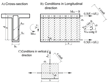
\[ \textsf{\textit{\footnotesize{\qquad Principe of Truss analogy for member under shear load.}}}\]
Cross-section under shear load is broken by cracks at an angle θ, from this reason the concrete diagonal with same angle as shear forces is resisting to the shear force. Compressive force of the diagonal can be expressed as Ved/sinθ. This force must be transferred by concrete surface, perpendicular to the compression diagonal bwzcosθ. The concrete tension stress in the compression diagonal is then equal:
\[ {{\sigma }_{c}}=\frac{{{V}_{Ed}}}{{{b}_{w}}z~\sin \text{ }\!\!\theta\!\!\text{ }\cos \theta }=\frac{{{V}_{Ed}}}{{{b}_{w}}z}\left( \tan \theta +\cot \theta \right)\]
Substituting \[{{\sigma }_{c}}={{\alpha }_{cw}}{{\nu }_{1}}{{f}_{cd}}\] and \[{{V}_{Ed}}={{V}_{Rd,max}}\] and expressing \[{{V}_{Rd,max}}\] we get equation for shear resistance of diagonal:
\[ {{V}_{Rd,max}}=~{{\alpha }_{cw}}~{{b}_{w}}~z~{{\nu }_{1~}}{{f}_{cd}}/\left( \cot \theta +\tan \theta \right)\]
To balance the vertical force component in the compression diagonal, shear reinforcement will be used. The size of the vertical force is based on the diagonal compressive stress in the concrete area which is corresponding to one single stirrup - \[{{\sigma }_{c}}{{b}_{w}}s{{\sin }^{2}}\theta\]. Limit stirrup force is given as \[{{A}_{sw}}{{f}_{ywd}}/s\].
Inserting σc, comparing with the limit force in the reinforcement, after modifications we get:
\[ \frac{{{A}_{sw}}{{f}_{ywd}}}{s}=\frac{{{V}_{Ed}}}{z}\tan \theta\]
Then expressing Ved as VRDs we get resistance of cross-section with vertical shear reinforcement:
\[ {{V}_{Rd,s}}=~\frac{{{A}_{sw}}}{s}z~{{f}_{ywd}}\cot \theta\]
The longitudinal shear force is transferred by longitudinal reinforcement and it can be determined as Vedcotgθ . Derivation of formulas above can be found in [4].
Using the program IDEA RCS it is possible to check only members with vertical shear reinforcement. In general following equations can be used:
\[{{V}_{Rd,s}}=~\frac{{{A}_{sw}}}{s}z~{{f}_{ywd}}\left( \cot \theta +\cot \alpha \right)\sin \alpha\]
\[{{V}_{Rd,max}}=~{{\alpha }_{cw}}~{{b}_{w}}~z~{{\nu }_{1~}}{{f}_{cd}}\left( \cot \theta +\cot \alpha \right)/\left( 1+{{\cot }^{2}}\theta \right)\]
Where
Asw is the cross-sectional area of the shear reinforcement,
s is the spacing of the stirrups,
fywd is the design yield strength of the shear reinforcement,
bw is the minimum width between tension and compression chords. To calculate the resistance VRd,max , the value of the section width must be reduced to the so-called nominal width of the cross-section in case the cross-section is weakened by cable ducts
bw,nom=bw-0,5ΣΦ for grouted metal ducts
bw,nom=bw-1,2ΣΦ for non-grouted metal ducts
υ = 0,6 pro fck ≤ 60MPa or pro fck > 60MPa,
αcw is a coefficient taking account of the state of the stress in the compression chord.
| Load | σcp = 0 | 0 < σcp≤0,25 fcd | 0,25 fcd < σcp≤0,5 fcd | 0,5 fcd < σcp≤1,0 fcd |
| Coefficient acw | 1,0 | 1+σcp/fcd | 1,25 | 2,5(1 - σcp/fcd) |
Tab. 1‑1 Determining coefficient αcw
Angle θ is the angle between the concrete compression strut and the beam axis perpendicular to the shear force. The limiting values of cotθ for use in a Country may be found in its National Annex. The recommended limits are given by the expression:
\[1~\le ~\cot \theta \le 2,5\]
Choosing the size of the angle θ can affect the value of the resistances. Dependence of resistances is visible in Figure 1.15. The figure shows that with increasing of angle θ the resistance VRd,max is increasing, and resistance VRd,s is decreasing. Resistance VRd,c is constant, since it is based on the truss analogy method.

\[ \textsf{\textit{\footnotesize{\qquad Dependency between shear resistance and angle q.}}}\]
Cross-section characteristics calculation for shear
To calculate the shear it is important to calculate the cross-sectional variables affecting the shear resistance. These variables include mainly shear-resisting section width bw, the effective depth d and lever arm z. The code [2] gives these values that directly correlate with the actual bending stress. But the problem is to determine these values when the direction of the resultant bending moments (or more accurately the direction of the resultant of section resistance) is significantly different from the direction of the resultant shear forces. In this case, the EC2 code doesn’t provide any recommendations.
Cross-section width resisting to shear bw
The IDEA RCS program calculates the cross-section width resistant to shear in the direction perpendicular to the resultant of shear forces. Depending on the article in the Eurocode this width is calculated as:
- The smallest width of the section between the resultant of compressive concrete and tensile reinforcement in the direction perpendicular to the resultant of shear forces for article 6.2.2 (a) and 6.2.3 (1)
- The section width in a direction perpendicular to the resultant of shear forces in the checked point according to article 6.2.2 (2)
Effective depth of a cross-section
Effective depth is usually defined as the distance of most compressed concrete fiber to the centre of gravity of the reinforcement. Because it is directly related to the bending, the distance is given as perpendicular projection to the gravity line of the plane strain.
This definition can be clarified so that instead of the centre of gravity of the tensile reinforcement the position of the reinforcement resultant of forces is used. During the development the IDEA RCS program the problem was solved: how to define the effective depth of the cross-section, for which the plane of bending loads doesn’t correspond with the direction of the resultant shear forces. Therefore, the effective depth is defined as the distance of most compressed concrete fibre to the resultant forces in the tensile reinforcement (based on bending stress) and in the direction of the resultant shear forces, see Figure 1.17.
Exceptional cases will occur if we are not able to determine the compressed fiber or resultant in the tensile reinforcement. In this case, we recommend using value 0.9 h (90% of section depth in the direction of the resultant shear forces). This value, the user can define in the IDEA RCS program by the setting of code variables.
Lever arm of internal forces
The lever arm of internal forces is in 6.2.3 (3) [2] and is defined as the "distance between tension and compression chords”. The code does not define how to proceed when the plane of acting bending moment is different from the direction of resultant shear forces. Therefore, as for the case of the effective depth, we define the distance in the direction of the resultant shear forces. Also here, we can face a similar exception cases, for example, the whole section is under compression, etc. In this case, we take value 0.9 d (90% of the effective section height). This value, the user can set in the IDEA RCS program by the setting of code variables.
Dependence between bending plane inclination and the resultant of shear force is clearly visible in Figure 1.18 and Figure 1.19. With an increase of inclination the values of effective height, lever arms and related resistances are decreasing. The limit state is 90°. For this inclination the lever arm of internal forces cannot be calculated, consequently the lever arm is equal to zero. In this case, the value specified in the setting of code variables is considered. By this, there is a jump at the end of the chart. This study proves the recommended maximum for inclination is about 20°.
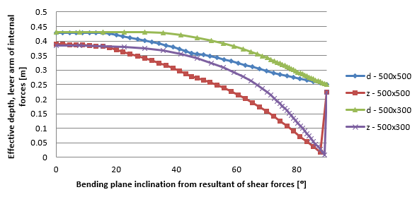
\[ \textsf{\textit{\footnotesize{\qquad Dependence between effective depth, lever arm to the bending plane inclination and the resultant of shear forces.}}}\]
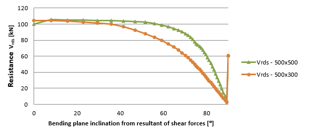
\[ \textsf{\textit{\footnotesize{\qquad Dependence between resistance Vrds to the bending plane inclination and the resultant of shear.}}}\]
As part of the testing of the RCS application, a study about dependency of shear resistance to changing the normal force was conducted. Resistance VRd,max is affected only by the coefficient αcw, see Fig. 1.20. Fig. 1.21 shows a constant value of resistance VRds. For VRdc resistance, the decreases cause increasing of normal force. The blue curve in Fig. 1.21 shows the resistance VRdc with neglecting the influence of cracks and it was calculated using the formula in section 6.2.2 (1) [2]. Jump in transition between pressure and tension is caused by contributed tensile reinforcement. The red curve is calculated using the formula in section 6.2.2 (2) [2]. After the first crack occurred the dependency curve is same as for 6.2.2 (1) [2].
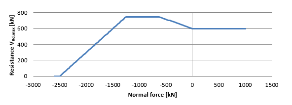
\[ \textsf{\textit{\footnotesize{\qquad Dependency curve of shear resistance VRd,max to normal force.}}}\]
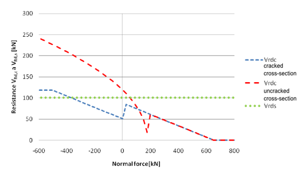
\[ \textsf{\textit{\footnotesize{\qquad Dependency of shear resistances VRd,c a VRd,s to normal force.}}}\]