How to set the lever arm properly
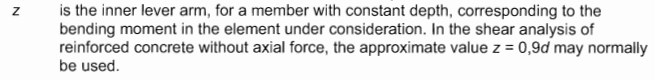
First, let's have a look at how the Eurocode defines the lever arm:
The cases
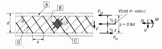
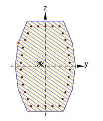
1) The direction of the biaxial bending moment and shear differs by less than 20°
This is the most common case where the direction of the biaxial bending moment (in-plane gradient of the strain plain) and the resultant shear force are the same or almost the same. The values of z and d are calculated automatically as shown in the figure.
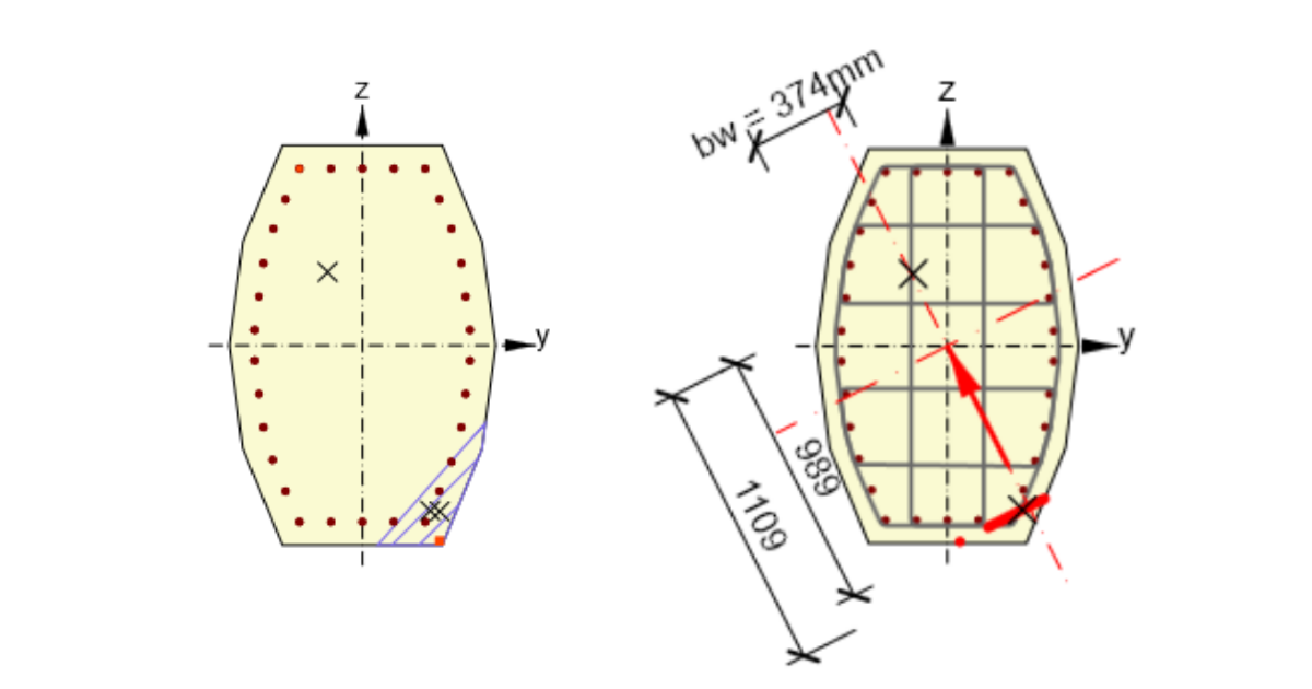
2) The direction of the biaxial bending moment and shear differs by more than 20°
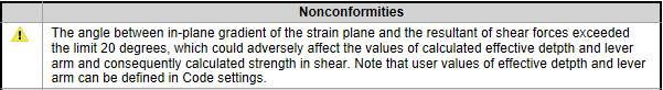
Lever arm z is defined in the same way. But for this case, the values of z is lower. And it could adversely affect consequently calculated strength in shear.
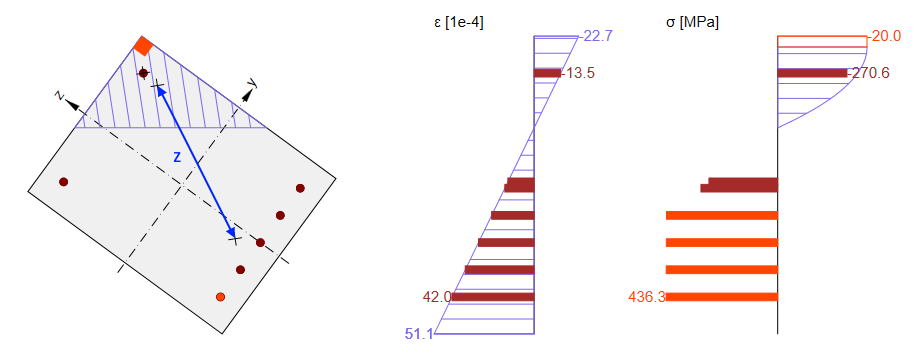
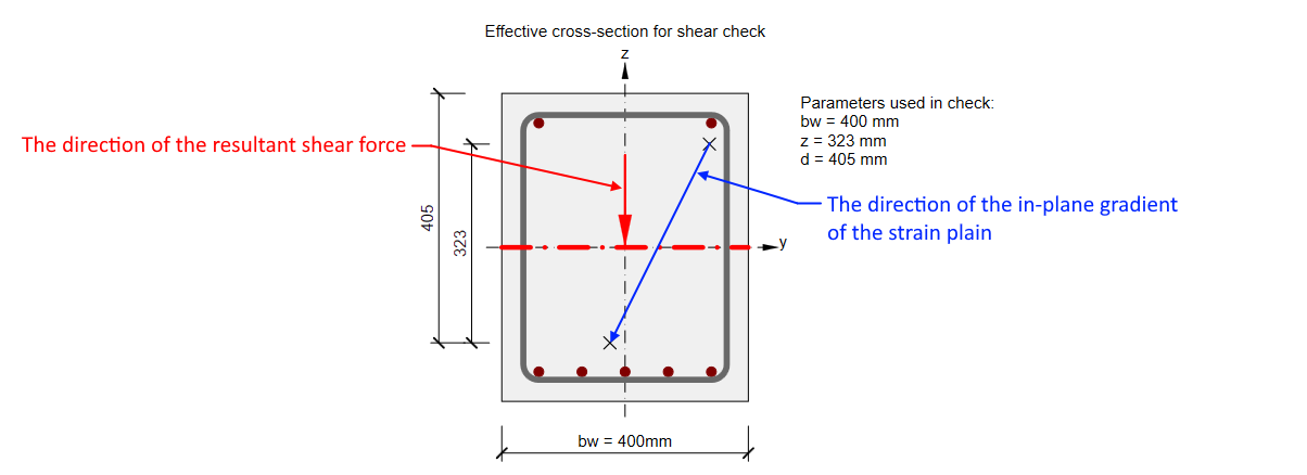
In this case, the value of z should be taken into account from the direction of the shear. So for our cross-section, it should be almost the same as in the previous case. You can read more in Shear in the Lever arm of internal forces chapter. That's why the nonconformity message appears.
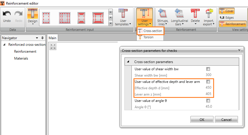
In this case, we recommend using the user-defined value of z. This value can be for example set as the distance of main layers of rebars (compressed layer and tensioned layer) in the Reinforcement editor -> User settings -> Cross-section.
3) Cross-section fully subjected to compression
No zones under tension appear in cross-sections fully subjected to compression. As the response can’t be found, lever arm value can‘t be determined from it and default value z = 0.9 d will be used. Although, this value is defined by the code with the assumption, that no axial force is introduced.
Conclusion
Always check the value of the lever arm z used for the shear check. As you could see, there can be unusual situations where the automatically calculated value should be manually adjusted.