Idea Statica
  • Steel
  • Concrete
  • BIM & workflows
  • Support & Learning
  • Pricing
  • Company
  • Steel overview
  • Connection design
  • Member design
  • Parametric design
  • Steel case studies
  • Concrete overview
  • Walls and D-regions
  • Anchoring design
  • Members & cross-sections
  • Concrete case studies
  • BIM overview
  • Supported integrations
  • Checkbot
  • Viewer
  • APIs
  • Support Center
  • E-learning & certification
  • Blog
  • Downloads & Licensing
  • Plans
  • Free community tool
  • Enterprise customers
  • Students & educators
  • How much will you save?
  • About us
  • Contact
  • Research & development
  • Authorized resellers
  • Meet our customers
  • Career
  • Steel
    Steel overviewConnection designMember designParametric designSteel case studies
  • Concrete
    Concrete overviewWalls and D-regionsAnchoring designMembers & cross-sectionsConcrete case studies
  • BIM & workflows
    BIM overviewSupported integrationsCheckbotViewerAPIs
  • Support & Learning
    Support CenterE-learning & certificationBlogDownloads & Licensing
  • Pricing
    PlansFree community toolEnterprise customersStudents & educatorsHow much will you save?
  • Company
    About usContactResearch & developmentAuthorized resellersMeet our customersCareer
14-Day Trial
14-Day Trial
  • Steel
  • Concrete
  • BIM & workflows
  • Support & Learning
  • Pricing
  • Company

Subscribe to our newsletter

Company

  • About us
  • Partners
  • Careers
  • Patent

Resources

  • Customer projects
  • Case studies
  • Connection Library
  • Verification books

Legal

  • EULA
  • Privacy policy
  • California Privacy
  • TOS Viewer
  • Licensing

Help

  • Contact
  • Quote request
  • Resellers
  • Downloads
FacebookInstagramLinkedInYouTube

© IDEA StatiCa 2009-2026

Trusted and used worldwide by engineers, fabricators & consultants.

Support CenterKnowledge Base ArticlesHow shear and normal forces affect rotational stiffness
How shear and normal forces affect rotational stiffness
SteelConnection designKnowledge baseConnectionRotational stiffness

How shear and normal forces affect rotational stiffness

This article is also available in
ENCZDEESFRITPTNLHUROKRPLTHTRVIZH

This article describes how shear force and normal force affect the rotational stiffness calculated in IDEA StatiCa Connection and they can affect joint classification.

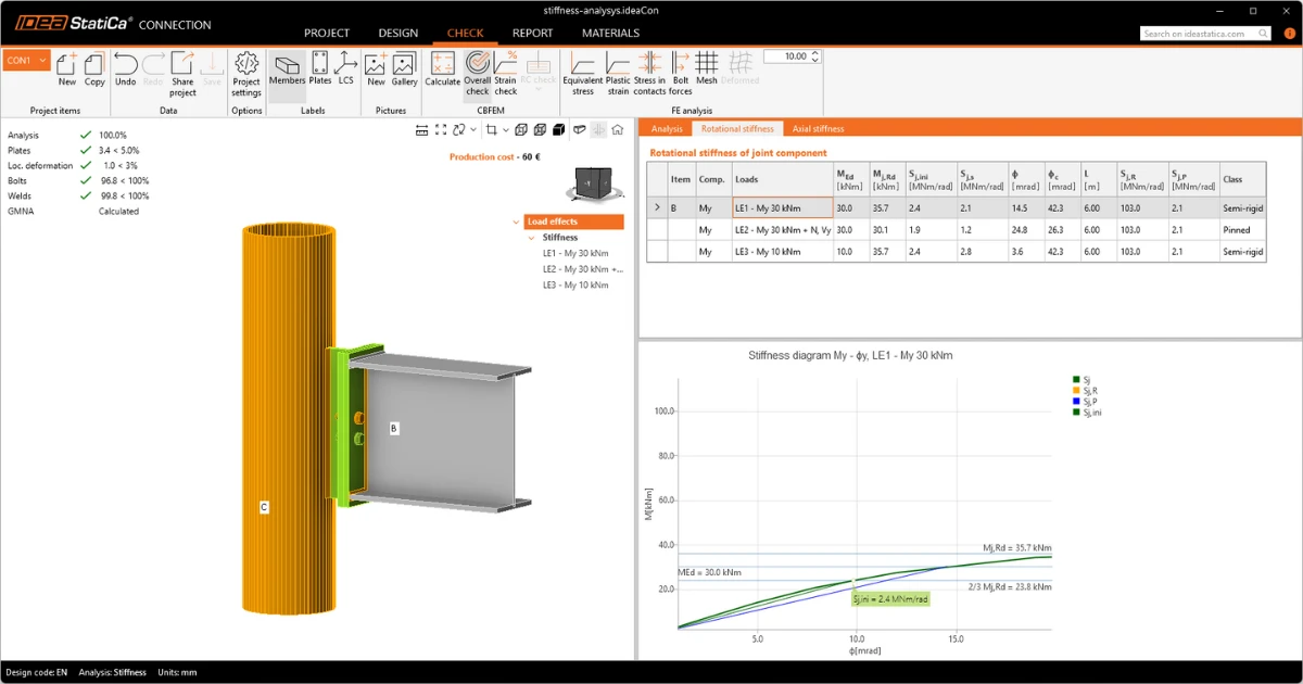
Stiffness analysis in IDEA StatiCa Connection is based on gradual loading of the analyzed member by the defined load effect. In each load step, the rotation of the analyzed member is calculated, and the resulting pairs of bending moment and rotation are plotted as the moment-rotation (M-φ) diagram.

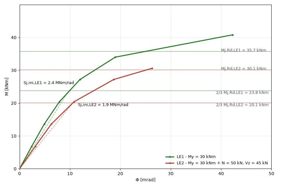
The rotational stiffness of the joint is then derived from this curve. If the load effect includes shear force and normal force in addition to the bending moment (LE2), the rotation and deformation of the joint may develop differently than under bending moment alone (LE1). This changes the shape of the moment-rotation curve and, consequently, the resulting stiffness:
Classification boundaries

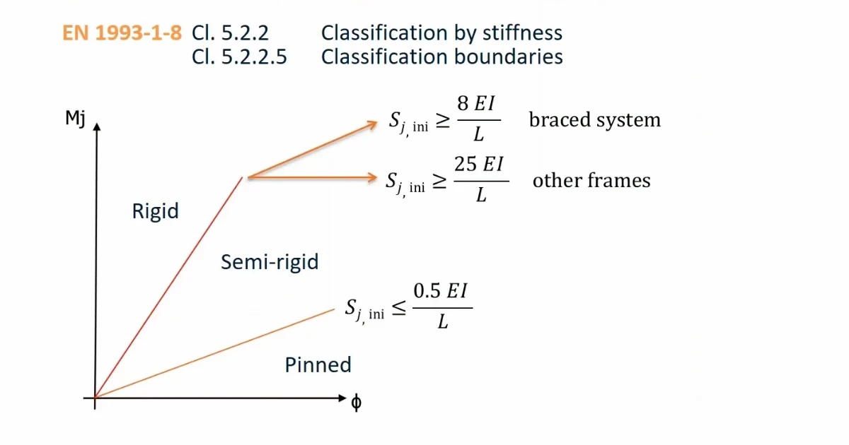
According to EN 1993-1-8, these boundaries depend only on the properties of the analyzed member (L, E, I) and on the factor kb, which reflects whether the frame is braced. 
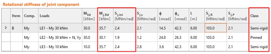
They are therefore independent of the load applied to the joint. In the table below, the boundary values Sj,R and Sj,P are identical for all load effects.
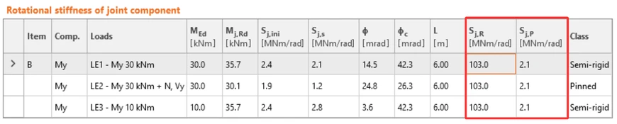
As mentioned above, the M-φ curve depends on the combination of internal forces in the load effect. All load components are applied simultaneously and increased proportionally in each load step, so shear and normal force grow together with the bending moment. Moreover, the resistance Mj,Rd decreases. Because Sj,ini is evaluated as the secant stiffness at 2/3 Mj,Rd, Sj,ini is read at a different point on the curve, and the classification can change.

The magnitude of the load, on the other hand, does not affect the result. If the applied loads are too small, they are all multiplied by a common factor until the joint resistance is reached, so only the ratio between the load components matters. This is confirmed by load effect LE3: with a bending moment of 10 kNm instead of 30 kNm, it gives the same Mj,Rd and Sj,ini as LE1.