Model type - additional boundary condition
For a complete understanding of this article, it is recommended to first read the article Principles of Loading in Connection, which explains in detail the composition of the CBFEM computational model, boundary conditions and loading principles.
The Model type functionality in Connection is used, for example, when it is necessary to prevent model singularity in a single screw connection. It is also used for connections with U-sections connected to columns where it is necessary to restrict the twisting of the connected profile, and also for the analysis of eccentric connections.
The Connection application allows you to set the so-called Model type for the connected element in the following variants:
- N-Vy-Vz-Mx-My-Mz
- N-Vy-Vz
- N-Vz-My
- N-Vy-Mz
By default, the Model Type of the connected element is always set to N-Vy-Vz-Mx-My-Mz. This means that all six internal forces can be assigned to the element and these will be entered into the calculation model. By activating Model Type N-Vy-Vz, N-Vz-My or N-Vy-Mz, additional boundary conditions (supports) are added to the CBFEM computational model on the edited connected element. We will explain in detail what this is good for, what exactly an additional boundary condition means, what effect it has on the calculation model, the calculation results and what the limitations are. We will demonstrate it on two examples. The first chapter focuses on the N–Vy–Vz model type, while the second chapter addresses the N–Vz–My model type.
1. Type of N-Vy-Vz model for solving singularities in the model
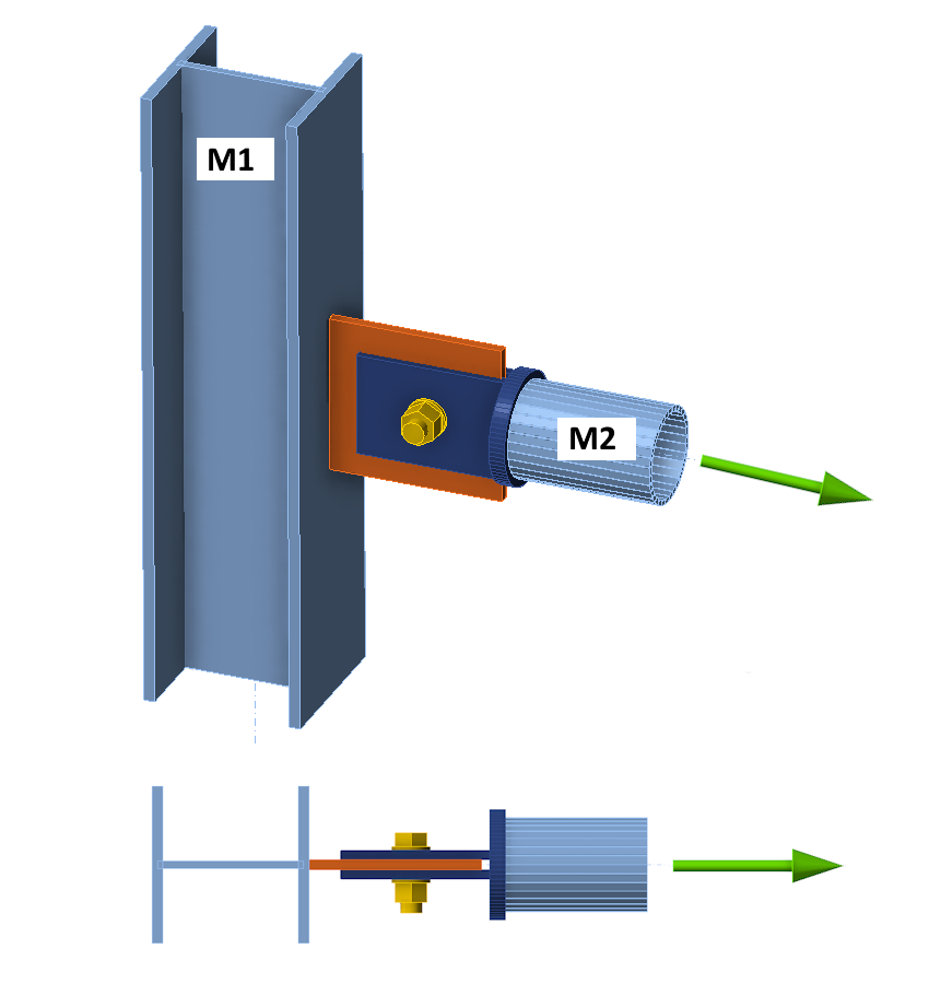
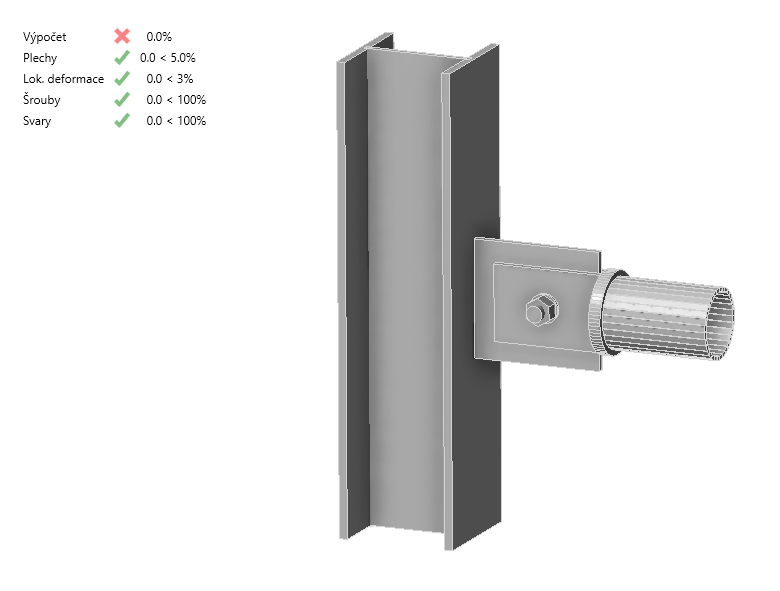
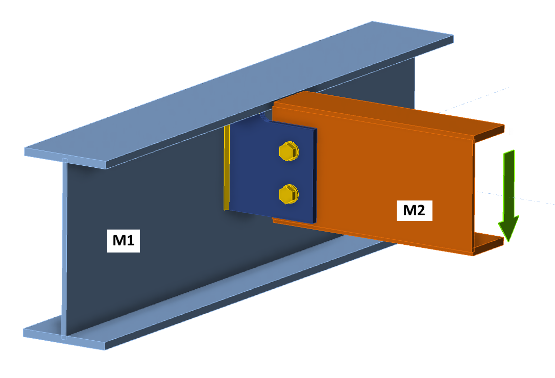
Consider the following simple connection consisting of a column M1 of HEA section and a horizontal element M2 of tubular section. M2 is connected to the column M1 via a connecting plate (gusset plate) on the side of the column and two tongues with one bolt on the side of the element M2. The connection is completely symmetrical and without any eccentricity. The M2 member is loaded only by axial force - it is therefore a simple pin-connected tie or strut.
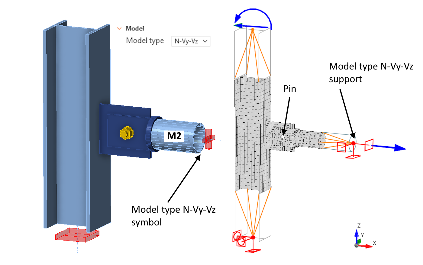
The following figure shows a schema of a computational model of the connection, with the Loads in equilibrium turned on. Which means that the bearing member (column M1) in the model has supports only at the lower end, represented by the red rectangle in the 3D scene.
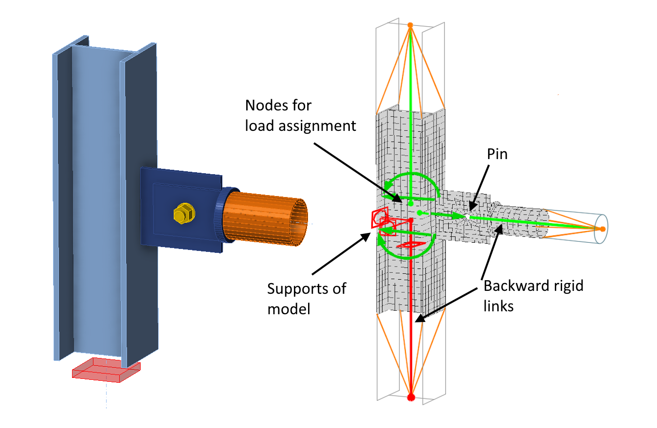
As described in detail in the mentioned article, the loading and supports (boundary conditions) are applied to the beginning of the so-called backward rigid links at the center of the joint in the CBFEM model. These rigid arms provide an automatic transformation of the loads (bending moments) from the centre of the joint to the ends of the condensed superelements (represented by orange lines in the picture). However, the introduction of the backward rigid links in the following explanation would unnecessarily clutter the explanation of the principles of the Type Model functionality on the connected element. The backwards rigid links are therefore omitted for the following explanation. In the schema of the computational model, the load is shown at the ends of the condensed superelements. Also, boundary conditions and additional "model type supports" are shown (see below). This simplification does not compromise the accuracy of the description of the computational model's function, since the calculated stresses will be identical regardless of whether the supports are applied at the beginning or the end of the backwards rigid links.
It is clear that the M2 tube is connected to the column with a hinge, and therefore acts as a mechanism. The calculation in the Connection application then terminates due to a singularity, resulting to in 0% load transfer.
1.1 Type of model N-Vy-Vz - load in equilibrium ON
To eliminate the singularity, there is an option in Connection to select the model type N-Vy-Vz for the connected member M2. Three rotational supports are then added to the end of the M2 member - note the missing Mx, My, and Mz moments in the model type description. These additional supports are specified in the local coordinate system of the connected member. In the following text, the term model type supports is used as a shorthand for these additional supports defined through the Model Type functionality. The computational model can be represented as follows.
The additional model type support for rotation about the Y-axis then avoids singularity in the computational model, and the analysis proceeds without a problem. It should also be noted that specifying the bending moments Mx, My, and Mz is not permitted for member M2 in the load effects table, since these moments would be directly transferred by the model type supports and therefore not applied to the computational model.
The following figure and animation show the result of the calculation with additional model type support. The model has already transferred 100% of the load. The model supports and condensed superelements (orange lines) are drawn into the figure, but the application does not currently allow them to be displayed.
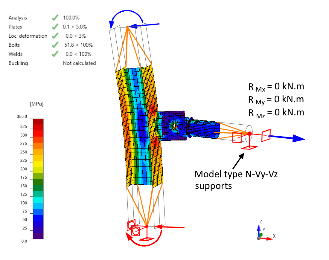
he deformation shows that the Ry model type support keeps the M2 member in place, with rotation occurring at the single-bolt joint. "In this case, the model type support serves only a stabilizing function (preventing singularity), and with this configuration and load, no reactions occur in the additional model type supports. However, this may not always be the case.
For a computational model of a joint in Connection without using the Model Type function, the model is statically determinate. Six degrees of freedom are restrained, and the supports of the model do not prevent its deformation nor affect the final stress distribution. However, when additional supports are introduced through the model type, the model becomes statically indeterminate. The free deformation may therefore be constrained, leading to so-called residual reactions in the model-type supports. These reactions may, but do not necessarily, affect the accuracy of the stress calculation. A detailed explanation of this issue is provided in the following section.
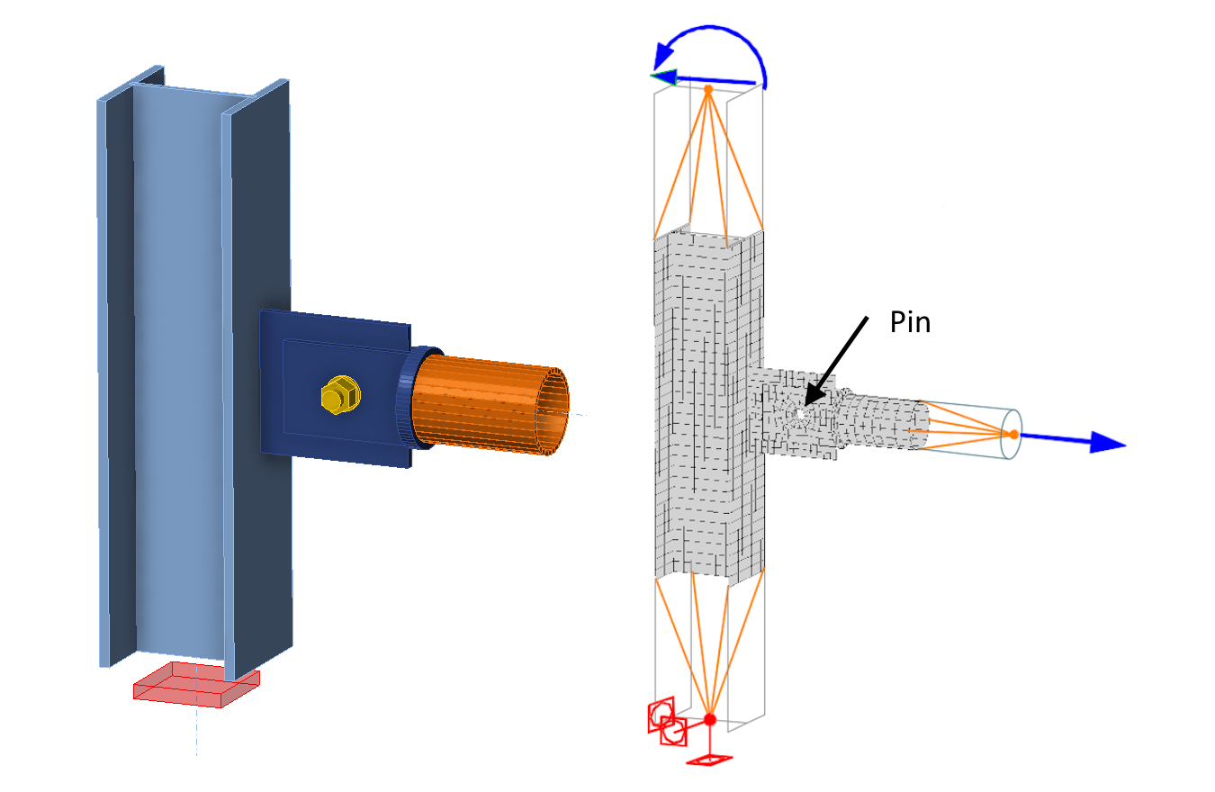
Let's consider an identical connection but with a different type of loading where only the column is loaded, specifically moments about the soft axis of the HEB section are applied. Moments cause the column to bend outside the XZ plane. No load is specified on the connected member M2! The stresses and deformation of the model are illustrated in the figure and animation below.
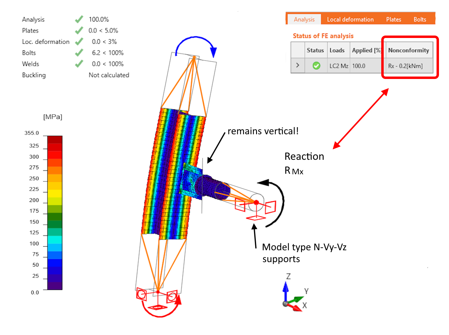
The notional center of the connection (the intersection of elements M1 and M2), and thus the connecting plates (gusset plate and tongues) of the connection, is moving in the Y direction while rotating about the X axis. However, the connected member M2 is supported against rotation about the X-axis (note that the LCS of element M2 is identical to the GCS), so a non-zero moment reaction RMx must occur in the additional model type support. The connecting plates undergoes torsion, despite the connected member M2 not being loaded at all.
These so-called residual reactions in the model type supports are listed in the Analysis table after the calculation. The additional model type supports are entered in the local coordinate system of the connected element. The sum of all residual reactions from all elements, in the center of the joint and in the global coordinate system, is then listed in the analysis table.
The torsional stiffness of the connecting plate is relatively small and therefore, the calculated reaction is small. Nevertheless, non-negligible bending stresses were generated in the connecting plate due to the model type support. More details in the following section.
1.2 Effect of residual reactions on the results
It is clear that the residual reactions in the model type supports cause distortion in the stress analysis of the connection. For example, the stress in the connecting plates (gusset plate and tongues) in our example is then the sum of the effects:
- the specified load in the connection
- the stress introduced into the connection by the additional model type support - the residual reaction.
The degree of distortion of reality in the result depends on the size of the residual reactions. What distortion is negligible and what is not? Here, engineering judgement is required and the size of the residual reactions relative to the dimensions of the connecting plate and the dimensions of the cross-section of the M2 member must be taken into account. In general, therefore, relative to the connection arrangement.
Using the example of the connection studied above, but the column is loaded by bending about both axes.
In the case of this example, it is evident that the distortion of the stress calculation is acceptable because:
- The residual reaction RMx = 0.2 kN.m is negligible with respect to the size of the M1 - HEA 100 column and thus has a minimal effect on the stress in the column
- From the point of view of the connecting plates, the calculation is distorted more significantly, there is twisting due to the additional support. Additional stresses are generated, so the results are on the safe side for these elements.
If there is any doubt about the degree of accuracy in the connection analysis, or if a more accurate analysis is required, the design of the tie can be carried out separately on a model with the loads in equilibrium switched off. In this model, the bearing member has supports at both ends. Displacements and rotations of the center of the connecting member are thus minimized and negligible residual reactions will be generated in the rotational model supports. The assessment of the connecting plates (gusset plate and tongues), bolt, lid and welds is then not distorted by residual reactions.
The connection is only illustrative, but it is a general principle. A similar approach can be applied to more complex connections where multiple members are meeting at one node. The connection as a complex node in equilibrium can be assessed using the overall model with the load in equilibrium switched on and with all connections modeled so they do not require additional model type support N-Vy-Vz. For example, a single bolted connection is replaced by a welded connection. The goal is to introduce correct equilibrium loads to the connection node as a whole, not to model the connection of each sub-element in detail. The detailed assessment of the sub-connection of the element with Model Type N-Vy-Vz is then carried out separately on the model with the function Loads in equilibrium switched off.
2. Model type N-Vz-My for U profile shear connection
An example of the use of the Model Type N-Vz-My variant for the design of a shear connection of a beam and a U-shaped cross section will be shown.
Consider the following connection where a horizontal member M2 with cross section UPE is connected to a continuous member M1 with cross section IPE. The M2 member is bolted to M1 via a single gusset plate.
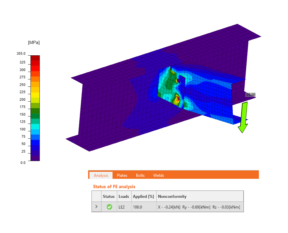
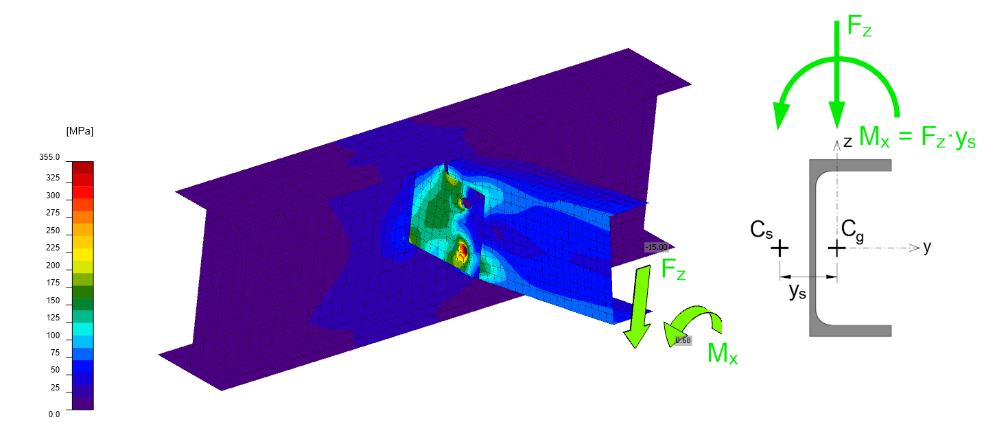
This type of connection focuses primarily on the assessment of the connection components (gusset plate, bolts, and welds), rather than on the overall equilibrium of the entire node. Therefore, in the following explanation, a variant of the calculation with function Loads in equilibrium switched off is used. The bearing member is supported at both ends and no load is applied to the element. Thus, only the connected element M2 is loaded with a shear force Vz = -15 kN. The bending moment My is zero at the node (more on the problem of shear connections in this article).
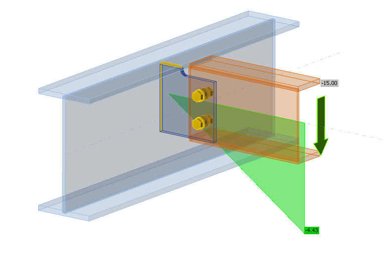
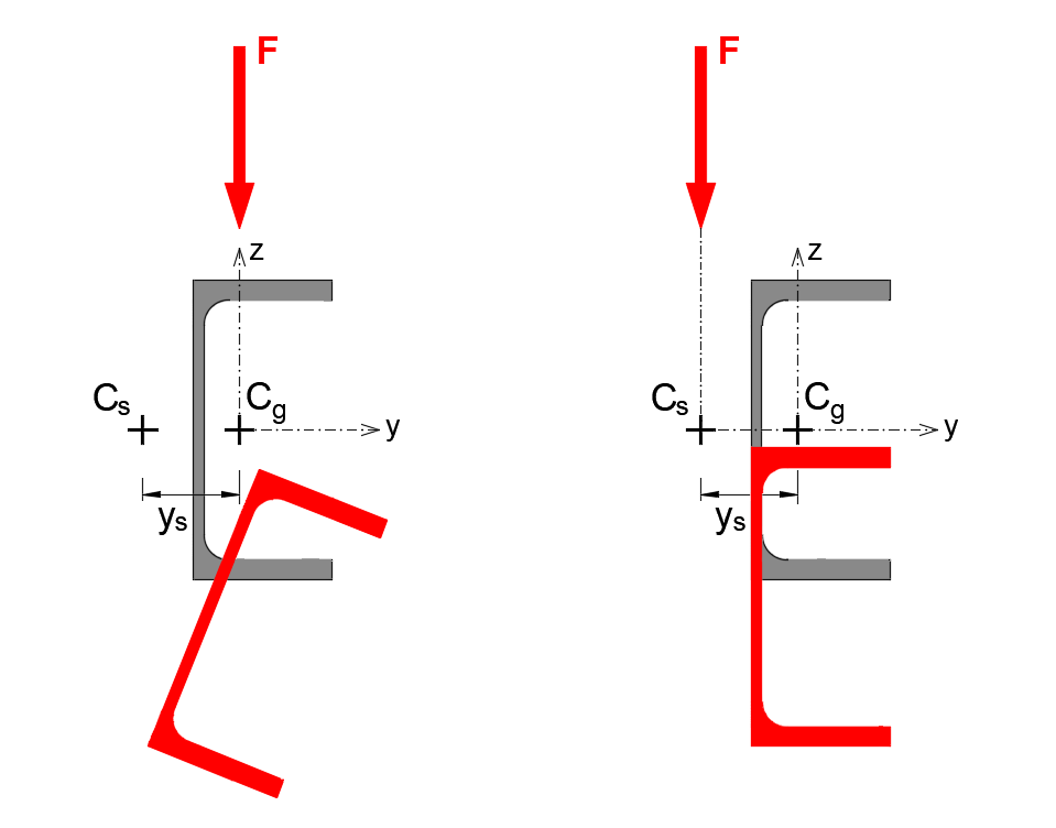
As is well known, if an unsymmetrical U-shaped cross-section is loaded in a vertical plane passing through the center of gravity, torsion of the beam occurs. When the shear load acts in a plane passing through the shear center, the beam M2 deforms only within the plane and no torsion takes place."
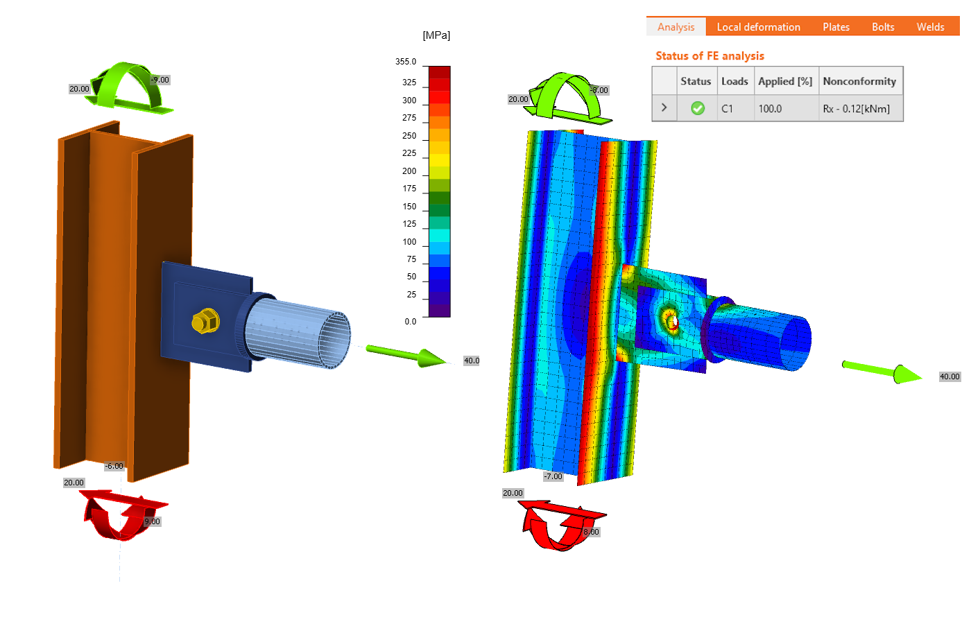
In IDEA StatiCa Connection, for all cross-sections, the load specified on the member is always applied at the center of gravity of the cross-section. When the M2 element is loaded with only a shear force, the deformation of the connection is as follows.
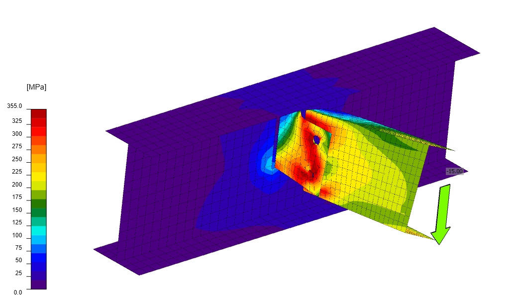
Significant twisting of the connected UPE beam occurs because the load was not applied at the shear center.
However, this behaviour of the connection may often not correspond to the actual action of the U-shaped beam in the structure. Torsion may be restrained, causing a member with a U-shaped cross-section to be ‘forced’ to deform primarily by bending in the vertical plane. This occurs, for example, when:
- torsion of a U-shaped member is prevented, for example, by a rigid reinforced concrete slab,
- the U-section is stabilized by another element against rotation.
In these cases, there are two possibilities to modify the connection model in Connection so that the connected beam deforms without twisting.
Load adjustment - torque calculation
As mentioned above, the torsion of the connected U section is induced by the torque Mx, which is defined by the shear force Vz and a lever arm that equals the distance between the centre of gravity and the centre of shear of the U section. By manually calculating and adding this torsional moment to the load of the attached member, we then eliminate the twisting of the member and achieve the bending deformation in the vertical plane.
Additional support against rotation - model type N-Vz-My
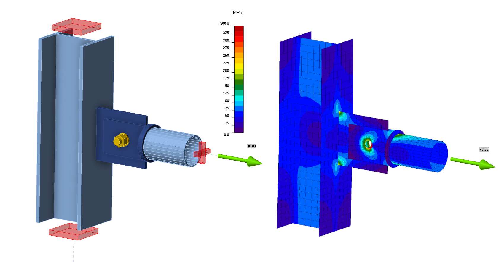
The second way to ensure bending deformation of the element without torsion is to use Type N-Vz-My for the attached M2 element. This will add supports for displacement in the Y direction and rotational supports around the Z and X axis of the element. It is the support for rotation about the X axis that prevents the element from twisting and achieves the same effect as when the torque is added manually. The model then looks as follows.
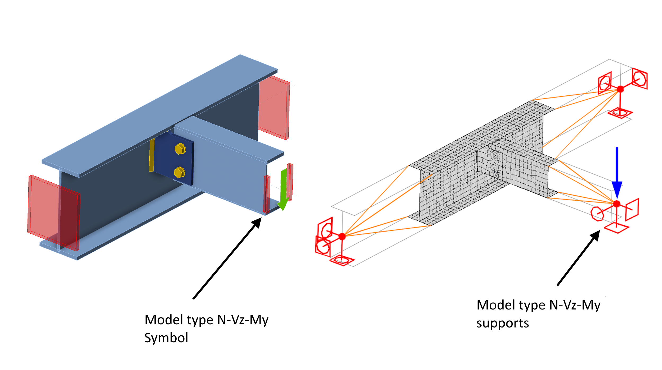
The deformation is following. The captured torque in the additional support is listed in the analysis result.