How to create and use a custom cross-section
IDEA StatiCa Connection offers the possibility to create your own custom cross-section, analyze its properties, and use it in your project as a part of a joint. Let's have a look at how to do it.
Building a general cross-section
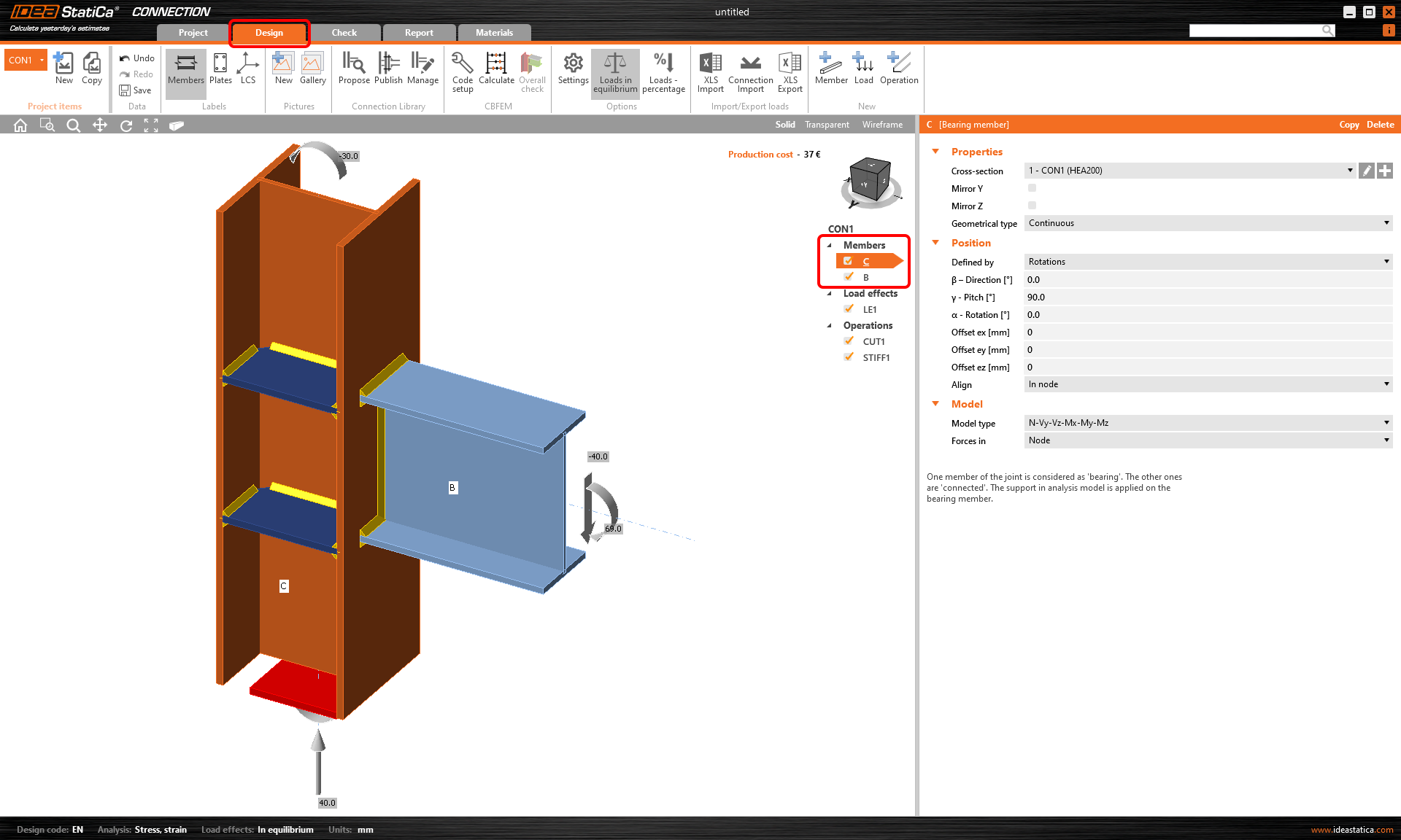
1. Within a project you have already created, click on the Design tab in the upper ribbon. In the list of Members, choose the one you wish to change the cross-section to.
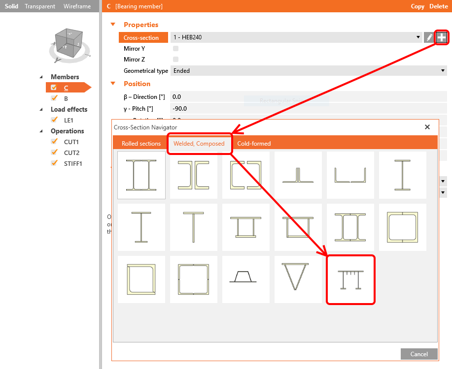
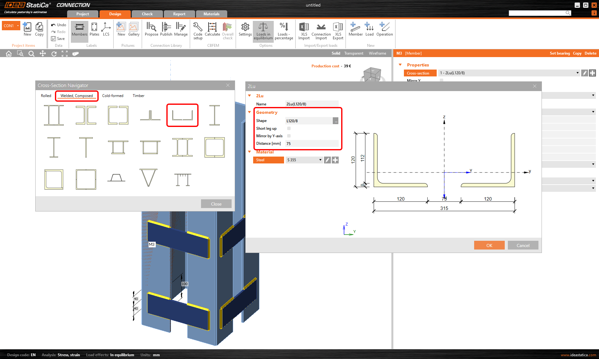
2. Click on the “plus” button to open the Cross-section navigator, and from the Welded, Composed tab, select the General steel cross-section.
3. A new window opens, which is the General cross-section editor, where we will create our custom cross-section. Click on the New icon and select General plate. Of course, you can use any of the cross-sections from the library and combine them to create anything that you want. Click OK to insert this plate in the editor.


Note about insertion points
In order to align and connect plates or cross-sections, the editor creates insertion points with an index number (1, 2, 3...) in all corners of an element. We can use these numbers to place the element in an exact position in the following principle: except for the first element, all the rest have a Master component (the reference element). When a second element is inserted, we need to define 3 things: the Master component, which of the points of the master component will be used as the Master point, and which of the points of the second element will be used as the Insert point.

4. Repeat Step 3 to insert a second plate (10x100 mm), and give it the same properties as the following image shows. The plate will be aligned to the left upper corner of the Master plate.

5. Repeat Step 3 to insert the third plate (10x130 mm) and give it the same properties as the following image shows. The plate will be aligned to the upper center of the Master plate.

Do you prefer seeing it rather than reading the text? Check the following video and see the workflow in a practical example!
Import from DXF
Sometimes, creating the cross-section by importing its middle line from the DXF file might be helpful and more convenient. See the following video and check out how the reference can be used.
Read about the limitations of the points proximity of the DXF curve in Limiting short lines in imported DXF.
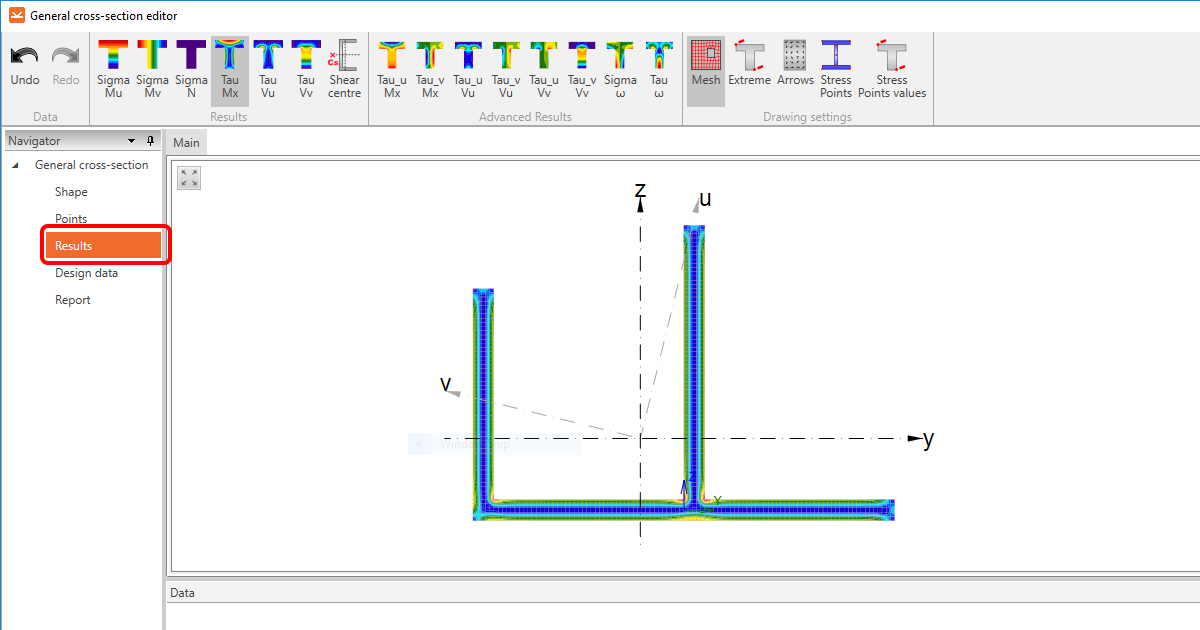
Results' check
There is a simple and quick way to check your general cross-section design in the General cross-section editor. FEM analysis can be used for the cross-section itself, and by evaluating the stress flow in the cross-section can be seen if the cross-section is designed correctly.
If you want to see the calculated properties of a cross-section, click on the Results section in the Navigator on the left.
If everything is correct, click OK to close the editor and insert the cross-section into your model.

You can also check the video to see how easy it is!
Important notes
Please pay attention to the following aspects:
The general cross-section editor provides the calculation of the geometrical properties of the cross-section using numerical methods. Nevertheless, the mesh which can be displayed here does not correspond to the mesh created during the stress/strain analysis of the loaded connection. Therefore, some results of stress provided by the General cross-section editor may differ from the ones from the analysis of the connection.
Also, please always check the continuity of the composed cross-section to see that all the plates are welded together. To do that, go to the Materials section in the top ribbon, and select the created general cross-section. If necessary, pull the vertical dividing border to the left and display the drawing of the general cross-section.
Look for the short thick blue lines connecting the individual plates. These constraints represent the connection of the corresponding nodes of the connection mesh and can be thought of as butt welds. In order for these constraints to be created, the plates must be positioned so that there is an intersection of their normal planes.
If the short lines are not present, the plates are not connected, and it is necessary to adjust their position within the cross-section.

Correct use of a general cross-section
There are many situations when you need to use a general cross-section. Usually, when a suitable cross-section cannot be found in the library. Or when the cross-section's geometry is too complex.
Nevertheless, there is one situation when it is necessary to pay attention to the selected workflow of setting the member. Let's show it in a practical example.
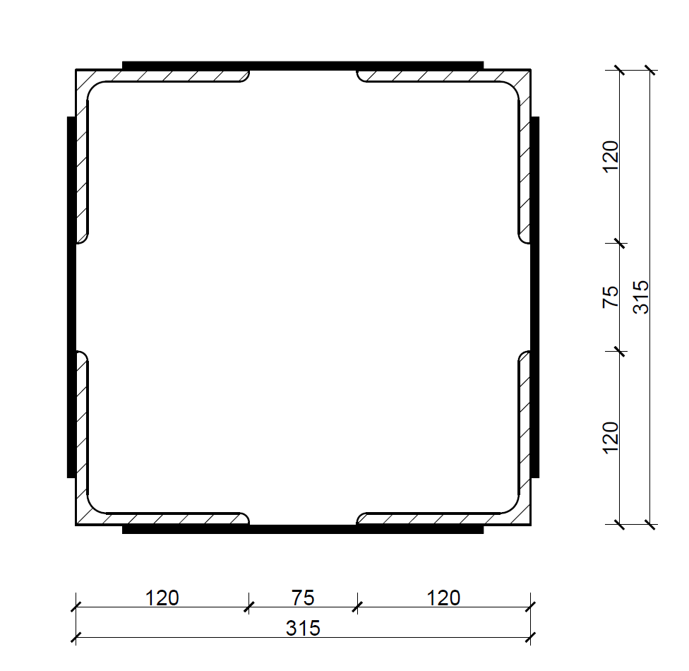
Assume we need to check a connection where the bearing member is defined by a composed cross-section made of four L-shaped sections connected together by stiffening plates. See the image below.
Defining such a cross-section using two separate members made of composed L-shaped sections would be a mistake!
Why it would be a mistake? Not only would it take significantly more time. But, in the IDEA StatiCa Connection application, only one member can be set as a bearing member, meaning just one member is supported in the model.
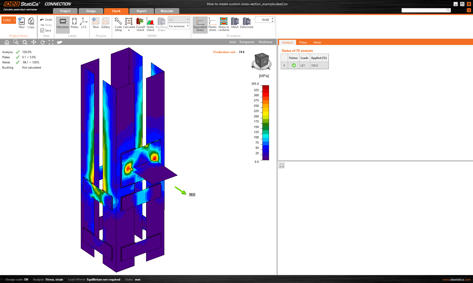
The fixed support is represented by the red lid, see the image below. So, in our case, one half of the whole member would be supported while the other one not.
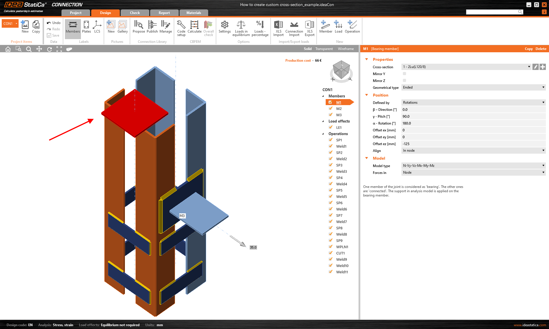
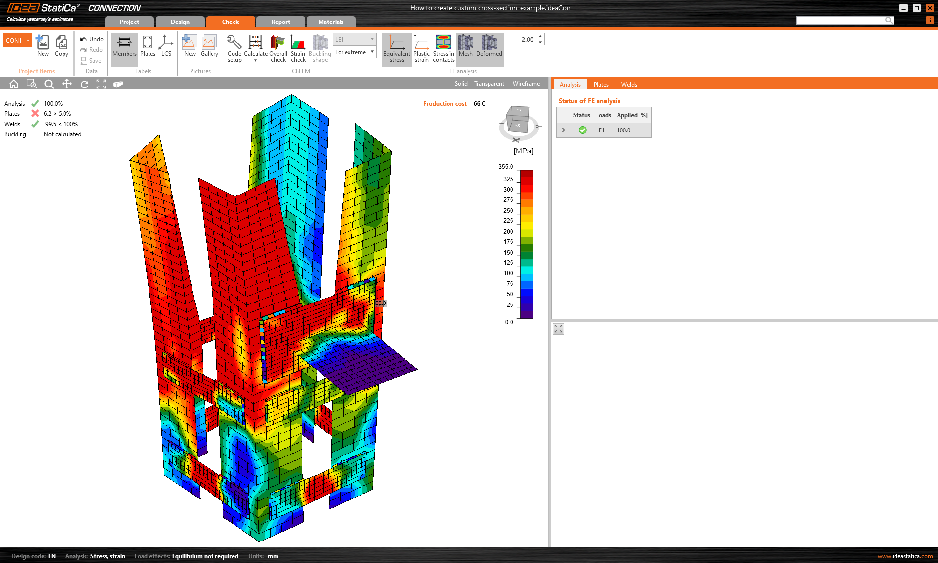
This would cause incorrect forces' distribution to the structure, hence wrong results and the structure's behaviour.
On the other hand, if you decide to build the same connection and cross-section using the General cross-section editor or import from the DXF file, the member will be supported properly.
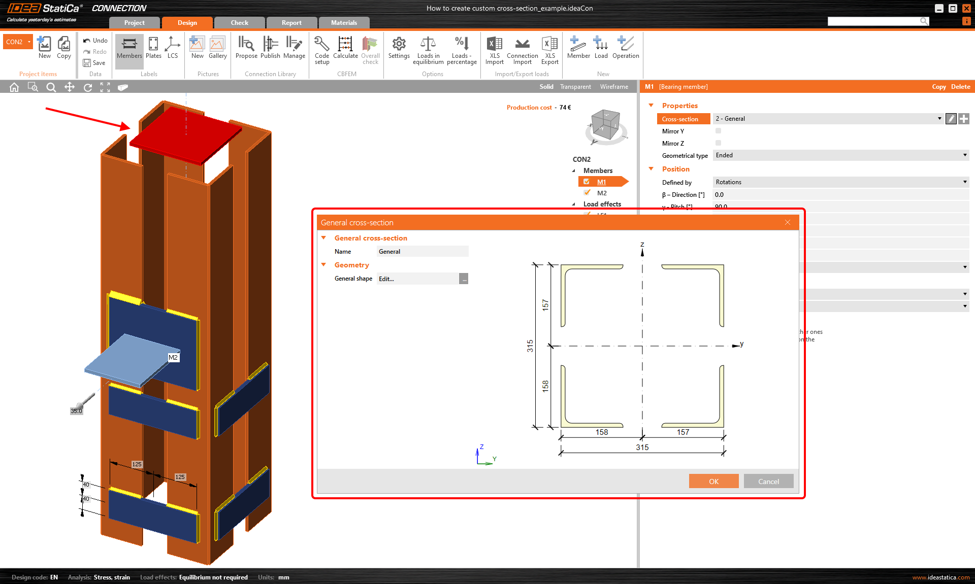
And you get correct results with the expected structure's behaviour.
Save your custom section
To use your customized cross-section in another project, save it in MPRL (Material and Product Range Library). Read more in the Saving of user-defined cross-sections to MPRL article.