IDEA StatiCa Connection lehetőséget kínál saját egyedi keresztmetszet létrehozására, tulajdonságainak elemzésére, és a projektben egy kapcsolat részeként való felhasználására. Nézzük meg, hogyan kell ezt megtenni.
Általános keresztmetszet felépítése
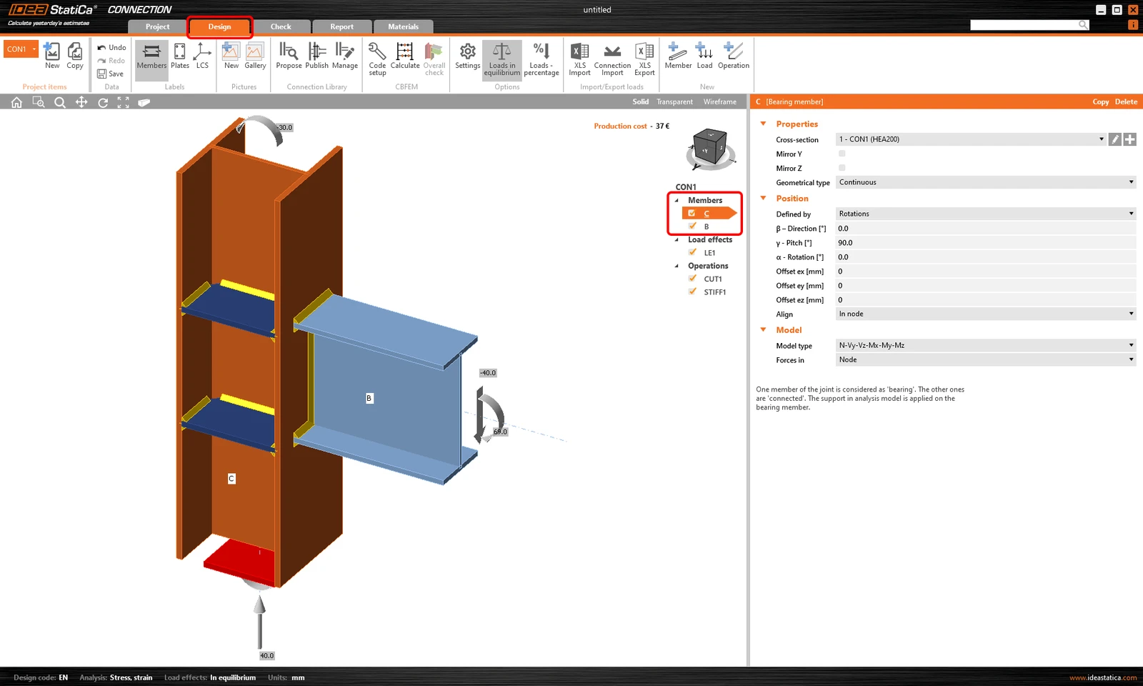
1. Egy már létrehozott projekten belül kattintson a felső szalagon a Tervezés fülre. A Szerkezeti elemek listájában válassza ki azt, amelynek a keresztmetszetét módosítani kívánja.
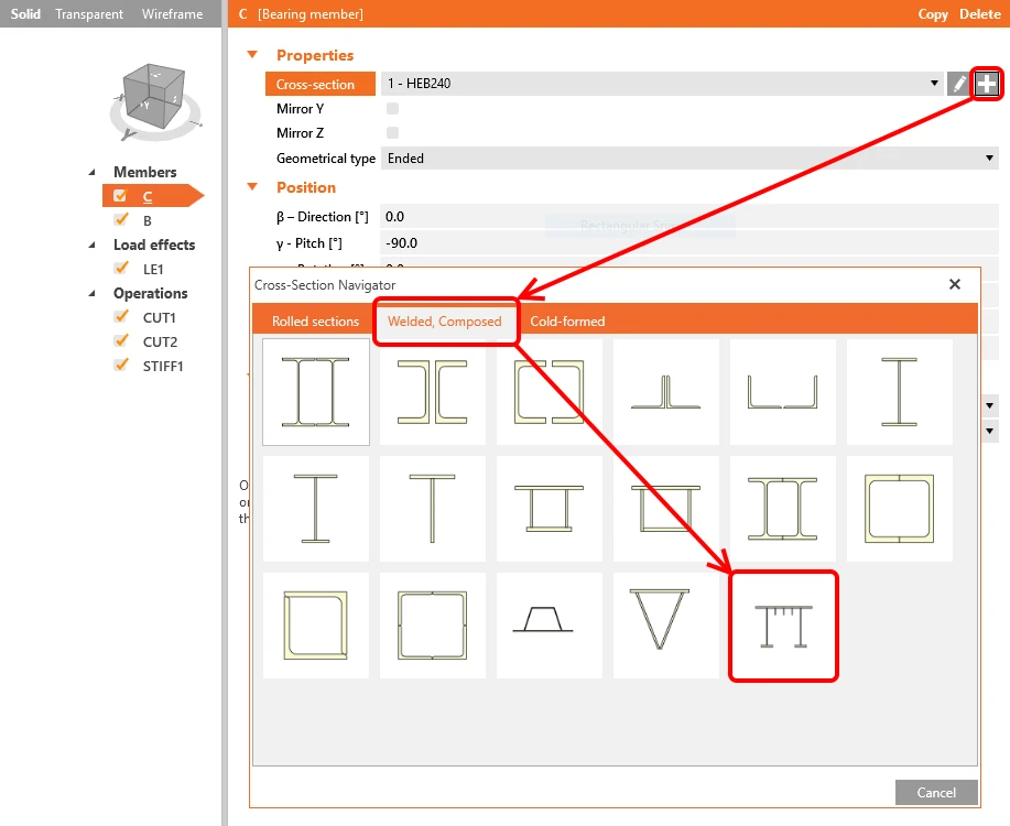
2. Kattintson a „plusz" gombra a Keresztmetszet-navigátor megnyitásához, majd a Hegesztett, összetett fülről válassza az Általános acél keresztmetszet lehetőséget.
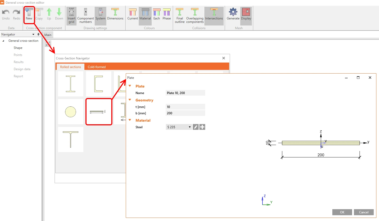
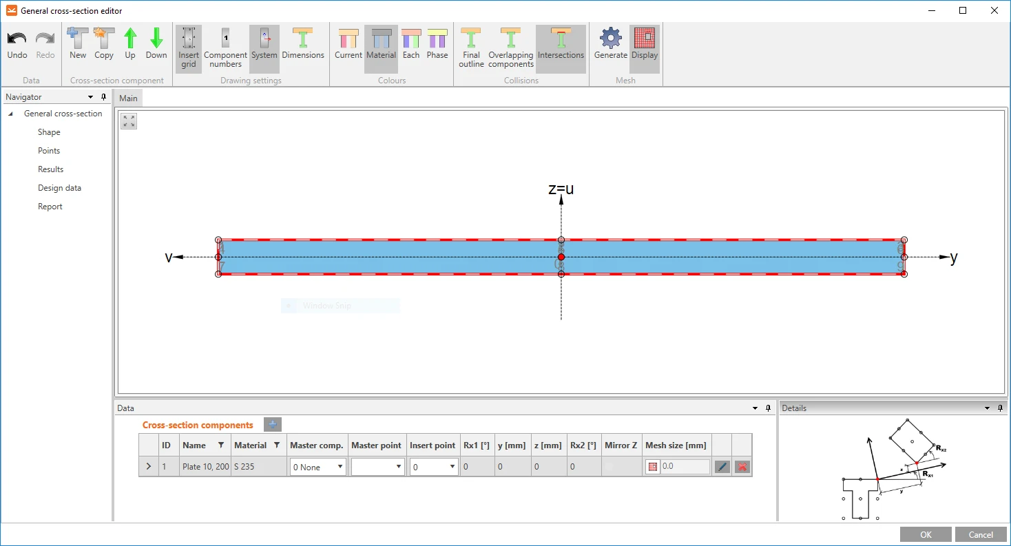
3. Megnyílik egy új ablak, az Általános keresztmetszet-szerkesztő, ahol létrehozzuk az egyedi keresztmetszetünket. Kattintson az Új ikonra, és válassza az Általános lemez lehetőséget. Természetesen a könyvtárból bármely keresztmetszetet felhasználhatja, és kombinálhatja őket, hogy bármit létrehozzon, amit szeretne. Kattintson az OK gombra a lemez szerkesztőbe való beillesztéséhez.
Megjegyzés a beillesztési pontokról
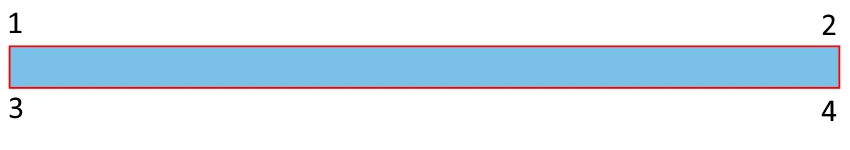
A lemezek vagy keresztmetszetek igazításához és összekapcsolásához a szerkesztő indexszámmal (1, 2, 3...) ellátott beillesztési pontokat hoz létre az elem minden sarkában. Ezeket a számokat felhasználhatjuk az elem pontos elhelyezéséhez a következő elv szerint: az első elem kivételével az összes többi rendelkezik egy Fő komponenssel (a referencia elemmel). Amikor egy második elemet illesztünk be, három dolgot kell meghatározni: a Fő komponenst, a fő komponens melyik pontját használjuk Fő pontként, és a második elem melyik pontját használjuk Beillesztési pontként.
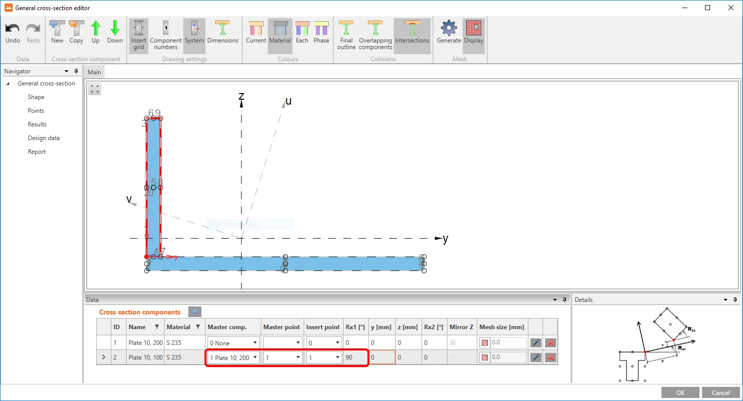
4. Ismételje meg a 3. lépést egy második lemez (10x100 mm) beillesztéséhez, és adja meg ugyanazokat a tulajdonságokat, mint amelyek a következő képen láthatók. A lemez a Fő lemez bal felső sarkához lesz igazítva.
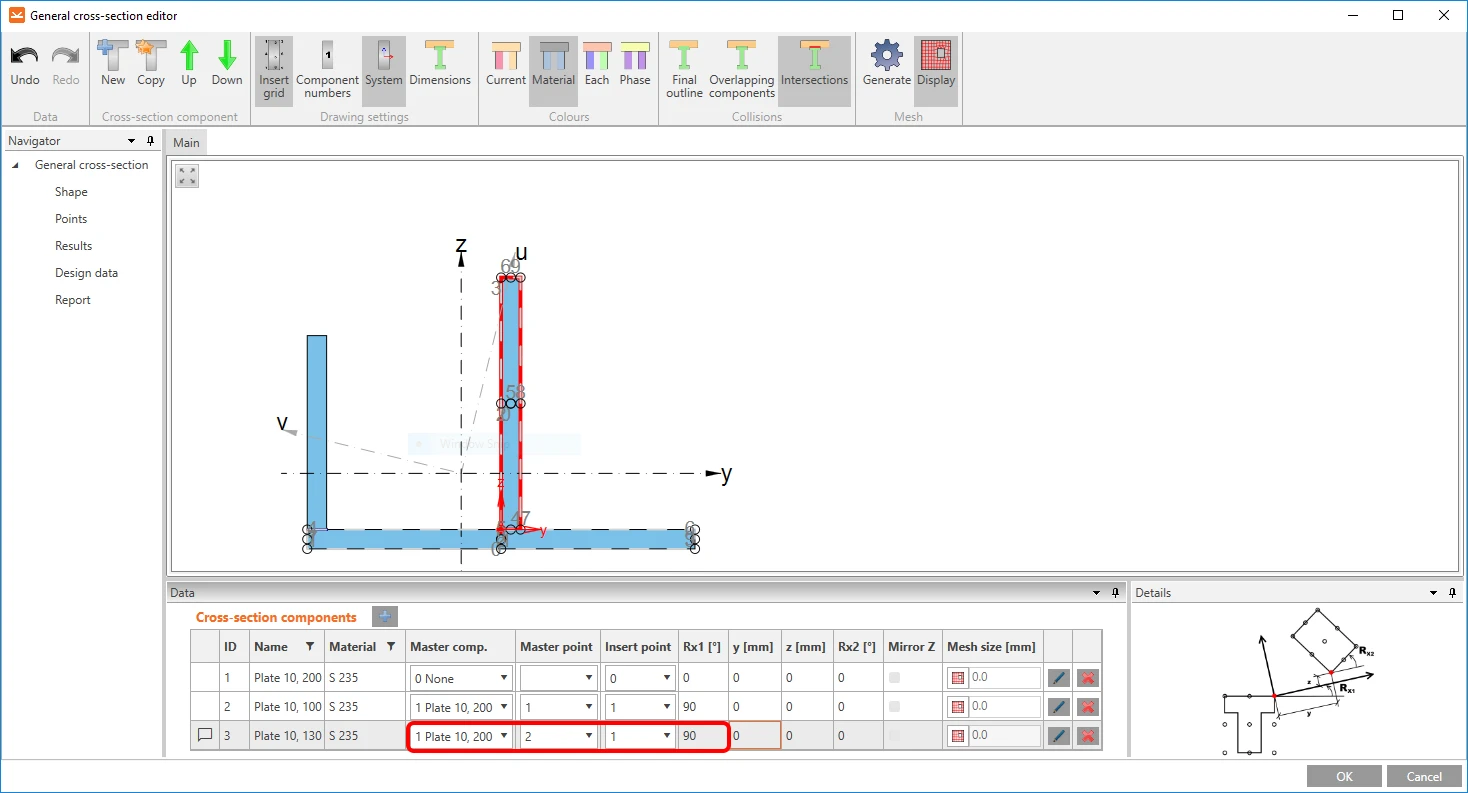
5. Ismételje meg a 3. lépést a harmadik lemez (10x130 mm) beillesztéséhez, és adja meg ugyanazokat a tulajdonságokat, mint amelyek a következő képen láthatók. A lemez a Fő lemez felső középpontjához lesz igazítva.
Inkább látni szeretné, mint olvasni? Tekintse meg a következő videót, és nézze meg a munkafolyamatot egy gyakorlati példán!
Importálás DXF-ből
Néha hasznos és kényelmesebb lehet a keresztmetszetet a középvonalának DXF fájlból történő importálásával létrehozni. Tekintse meg a következő videót, és nézze meg, hogyan használható a referencia.
Olvassa el a DXF-görbe pontközelségének korlátairól szóló részt a Rövid vonalak korlátozása importált DXF-ben cikkben.
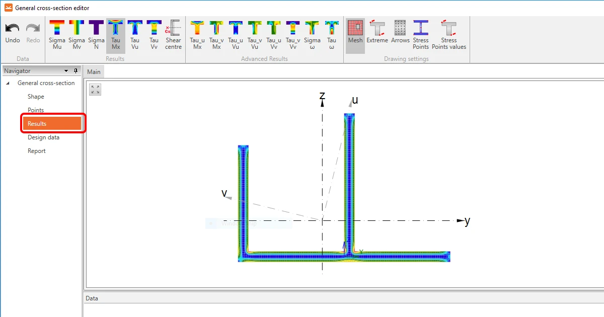
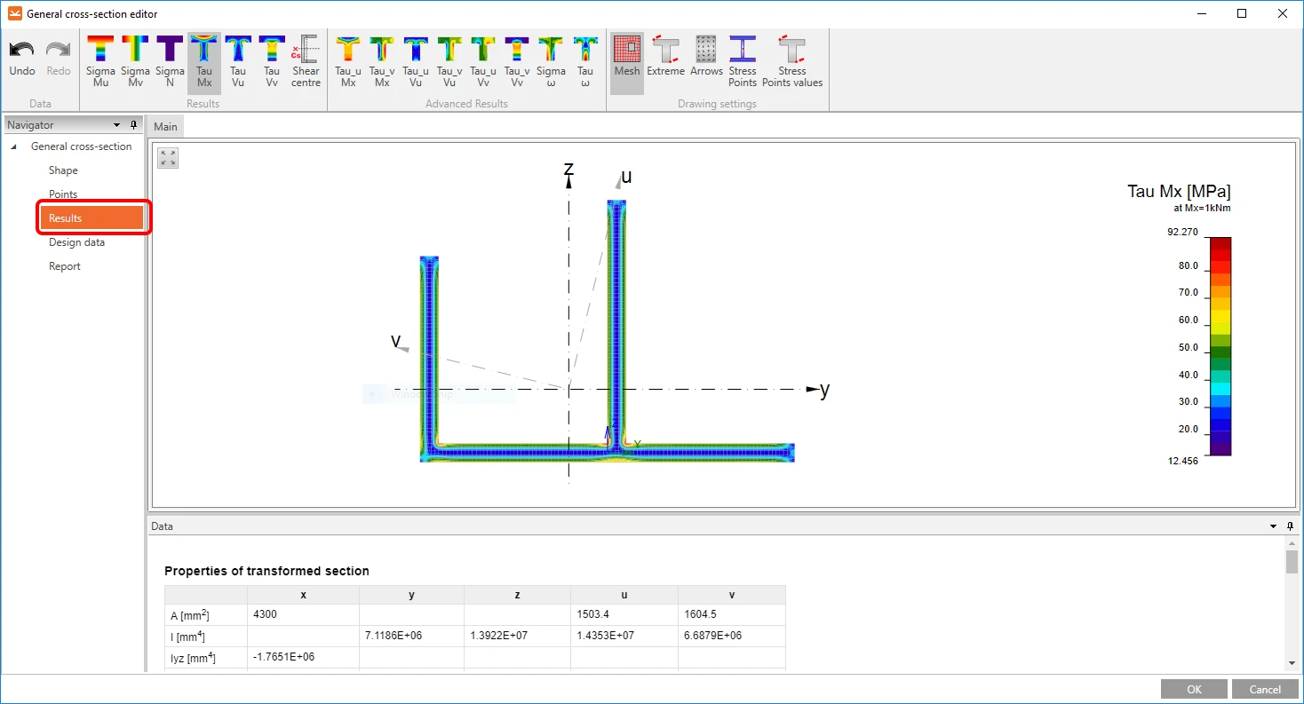
Eredmények ellenőrzése
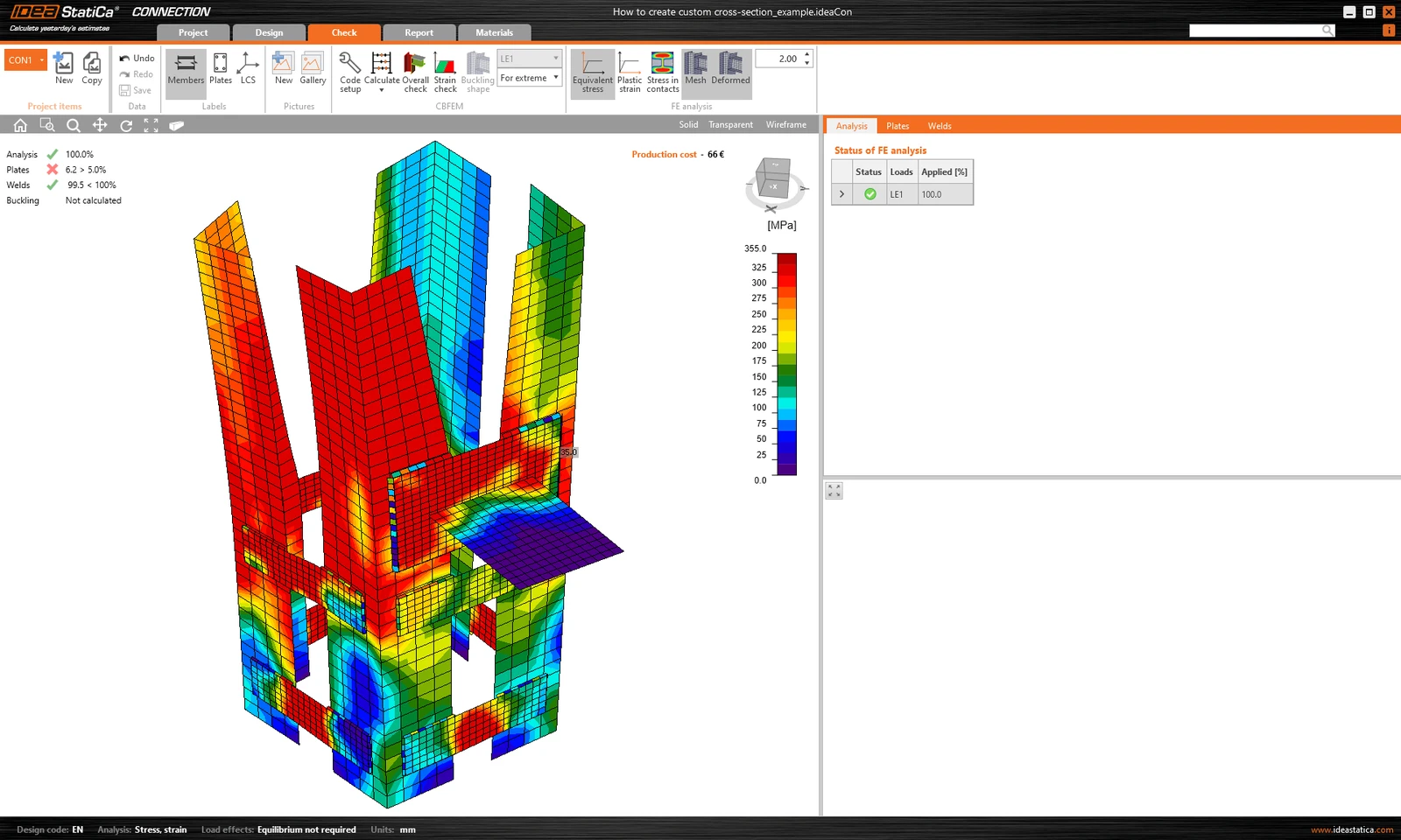
Az Általános keresztmetszet-szerkesztőben egyszerű és gyors módja van az általános keresztmetszet tervezésének ellenőrzésére. A végeselem-módszer analízis magára a keresztmetszetre is alkalmazható, és a keresztmetszetben lévő feszültségáramlás kiértékelésével megállapítható, hogy a keresztmetszet helyesen van-e megtervezve.
Ha meg szeretné tekinteni a keresztmetszet számított tulajdonságait, kattintson a bal oldali Navigátorban az Eredmények szakaszra.
Ha minden rendben van, kattintson az OK gombra a szerkesztő bezárásához és a keresztmetszet modelljébe való beillesztéséhez.
A videót is megnézheti, hogy lássa, milyen egyszerű!
Fontos megjegyzések
Kérjük, figyeljen a következő szempontokra:
Az általános keresztmetszet-szerkesztő numerikus módszerekkel számítja ki a keresztmetszet geometriai tulajdonságait. Mindazonáltal az itt megjelenítható háló nem felel meg a terhelt kapcsolat feszültség/alakváltozás analízise során létrehozott hálónak. Ezért az Általános keresztmetszet-szerkesztő által megadott egyes feszültségeredmények eltérhetnek a kapcsolat analíziséből kapott eredményektől.
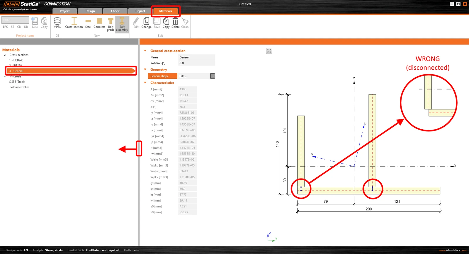
Kérjük, mindig ellenőrizze az összetett keresztmetszet folytonosságát is, hogy megbizonyosodjon arról, hogy az összes lemez össze van hegesztve. Ehhez lépjen a felső szalagon a Anyagok szakaszra, és válassza ki a létrehozott általános keresztmetszetet. Szükség esetén húzza a függőleges elválasztó határt balra, és jelenítse meg az általános keresztmetszet rajzát.
Keresse az egyes lemezeket összekötő rövid, vastag kék vonalakat. Ezek a kényszerfeltételek a kapcsolati háló megfelelő csomópontjainak összeköttetését képviselik, és tompahegesztésekként értelmezhetők. Ahhoz, hogy ezek a kényszerfeltételek létrejöjjenek, a lemezeket úgy kell elhelyezni, hogy normálsíkjaik metszéspontja legyen.
Ha a rövid vonalak nem láthatók, a lemezek nincsenek összekötve, és szükséges a keresztmetszetben elfoglalt helyzetük módosítása.
Általános keresztmetszet helyes használata
Számos helyzet adódhat, amikor általános keresztmetszetet kell használni. Általában akkor, ha a könyvtárban nem található megfelelő keresztmetszet, vagy ha a keresztmetszet geometriája túl összetett.
Mindazonáltal van egy olyan helyzet, amikor figyelni kell a szerkezeti elem beállításának kiválasztott munkafolyamatára. Mutassuk be ezt egy gyakorlati példán.
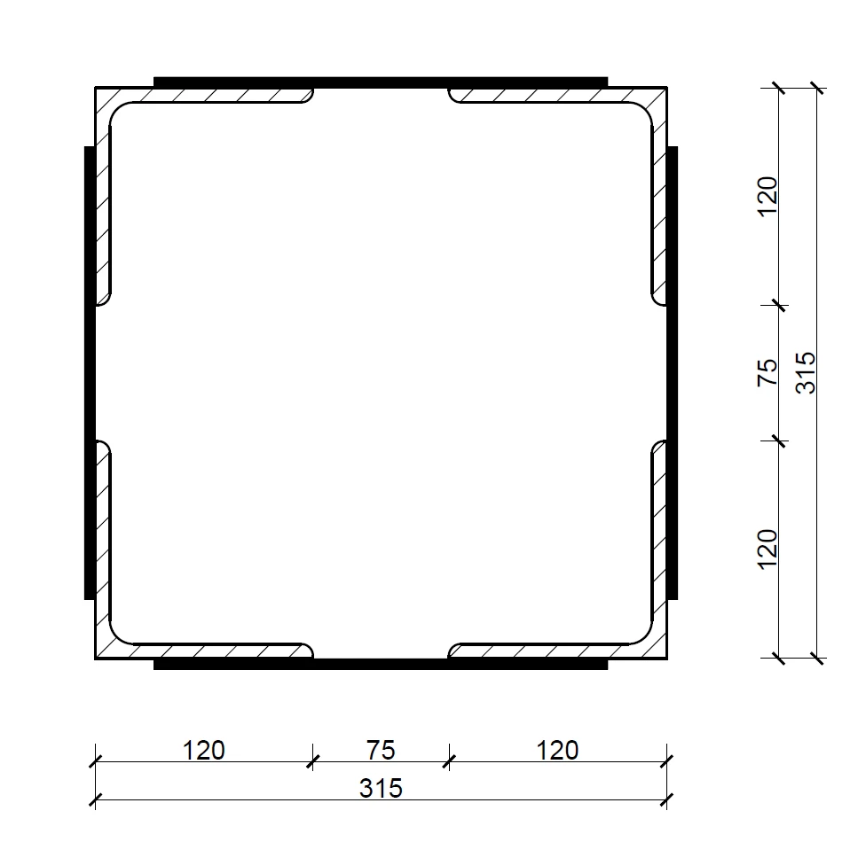
Tegyük fel, hogy egy olyan kapcsolatot kell ellenőriznünk, ahol a teherhordó szerkezeti elem egy összetett keresztmetszettel van meghatározva, amelyet négy L-alakú szelvényből állítottak össze merevítő lemezekkel összekötve. Lásd az alábbi képet.
Ilyen keresztmetszet meghatározása összetett L-alakú szelvényekből álló két különálló szerkezeti elemmel hiba lenne!
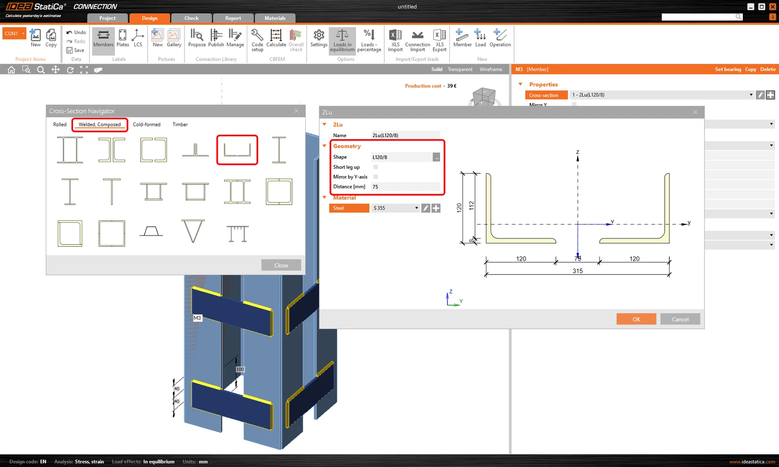
Miért lenne hiba? Nemcsak azért, mert jelentősen több időt venne igénybe. Hanem azért is, mert az IDEA StatiCa Connection alkalmazásban csak egy szerkezeti elem állítható be teherhordó elemként, ami azt jelenti, hogy a modellben csak egy szerkezeti elem van megtámasztva.
A merev megtámasztást a piros fedél jelöli, lásd az alábbi képet. Tehát esetünkben a teljes szerkezeti elem egyik fele meg lenne támasztva, a másik fele pedig nem.
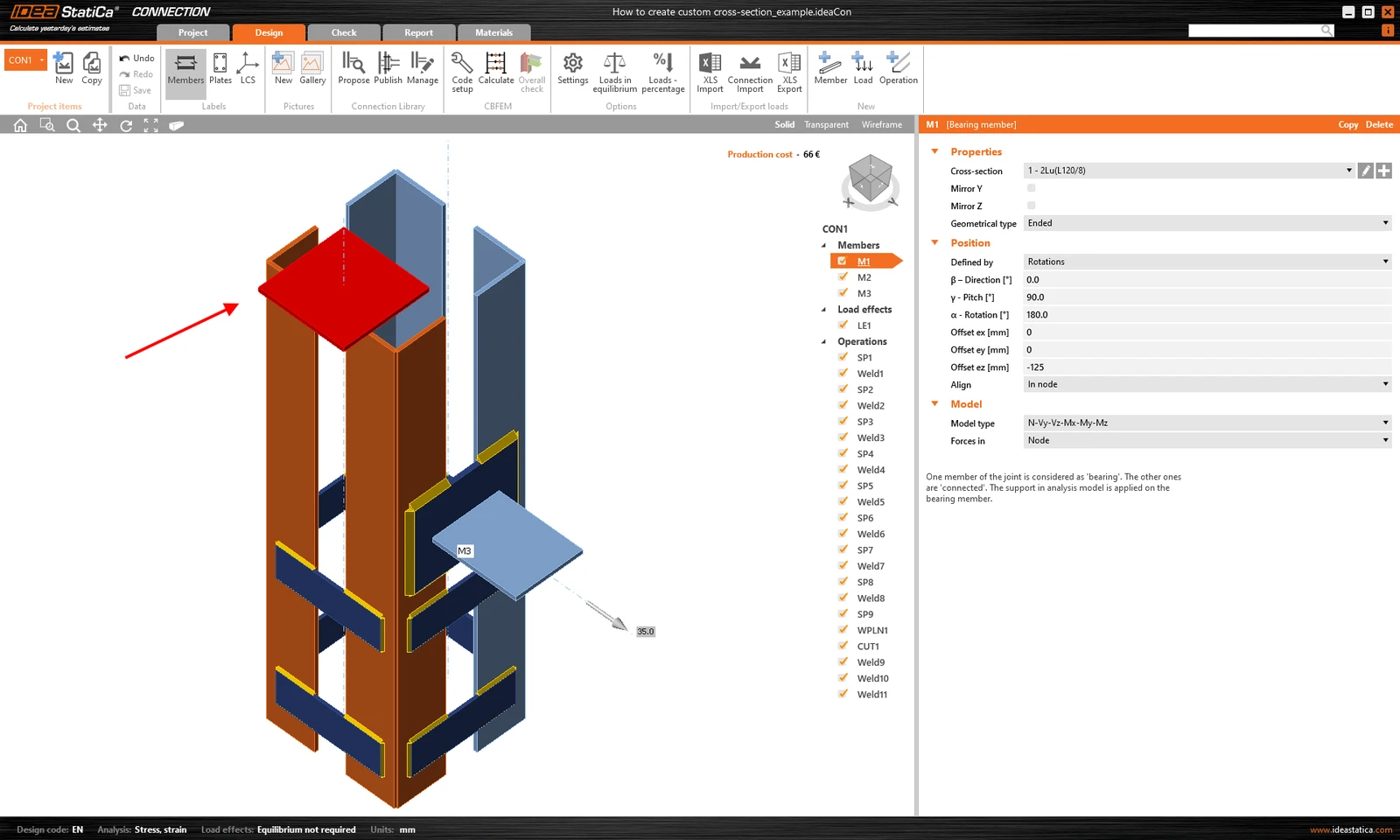
Ez helytelen erőeloszlást okozna a szerkezetben, következésképpen hibás eredményeket és a szerkezet helytelen viselkedését.
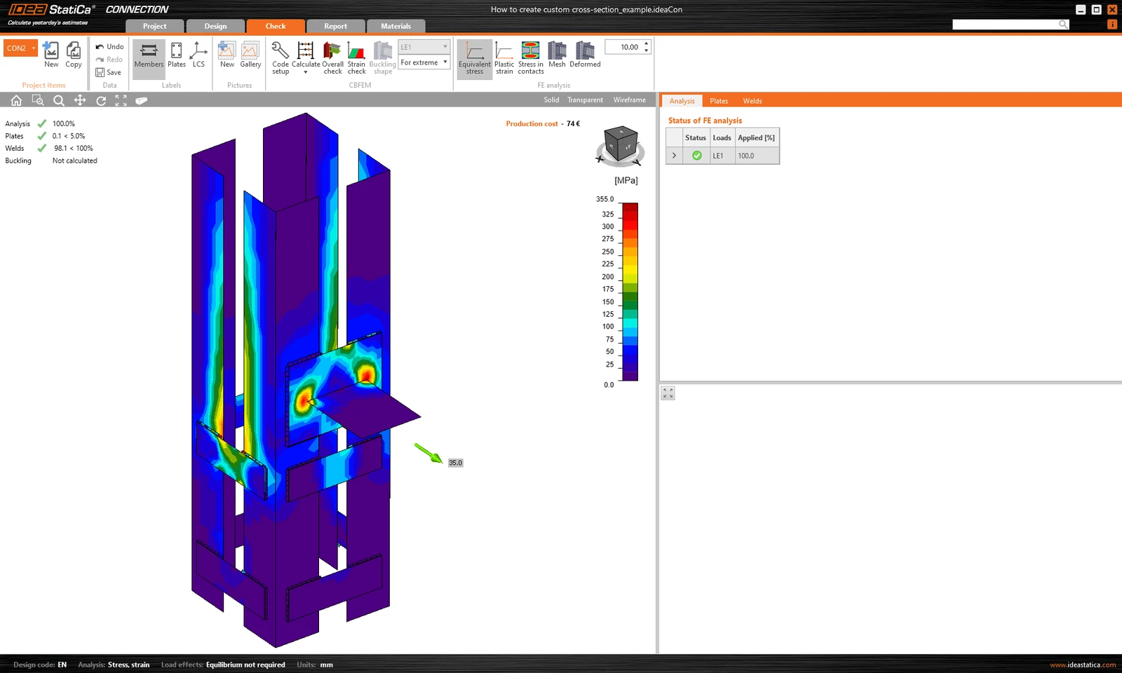
Másrészt, ha ugyanazt a kapcsolatot és keresztmetszetet az Általános keresztmetszet-szerkesztővel vagy DXF fájlból importálva hozza létre, a szerkezeti elem megfelelően lesz megtámasztva.
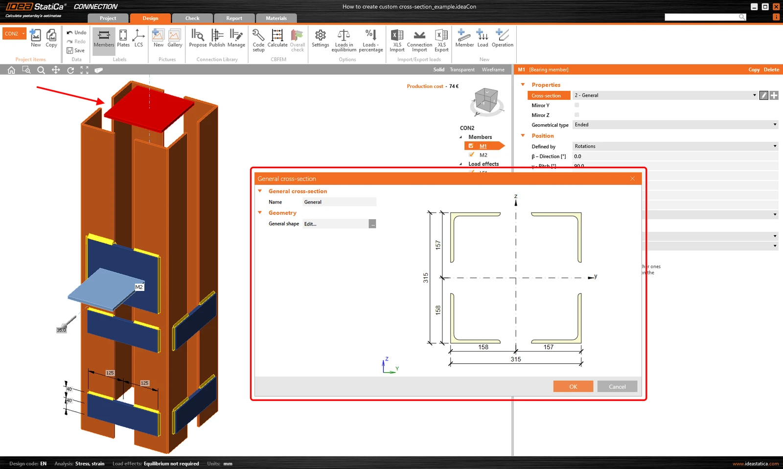
És helyes eredményeket kap a várható szerkezeti viselkedéssel.
Egyedi keresztmetszet mentése
Az egyedi keresztmetszet másik projektben való felhasználásához mentse el az MPRL-be (Material and Product Range Library). Bővebben olvashat erről a Felhasználó által definiált keresztmetszetek mentése MPRL-be cikkben.