Brace Connection at beam-column connection in a braced frame (AISC)
This verification example was prepared by Mahamid Mustafa in a joint project of The University of Illinois in Chicago and IDEA StatiCa.
Description
The objective of this example is verification of the component-based finite element method (CBFEM) of a Brace Connection at beam-column connection in a braced frame with the AISC design procedure. The study is prepared for the size of the brace, beam, column, connecting angles, geometry, the thickness of the plate, bolts and welds. In this study, ten components are examined: brace, beam flange and web, column flange and web, connecting angles, gusset plate, splice plates between brace and gusset plate, connecting angles to the column, connecting angles to beam, bolts and welds. All components are designed according to AISC -360-16 specifications. The connection presented is taken from AISC Design Guide 29.
Verification of resistance
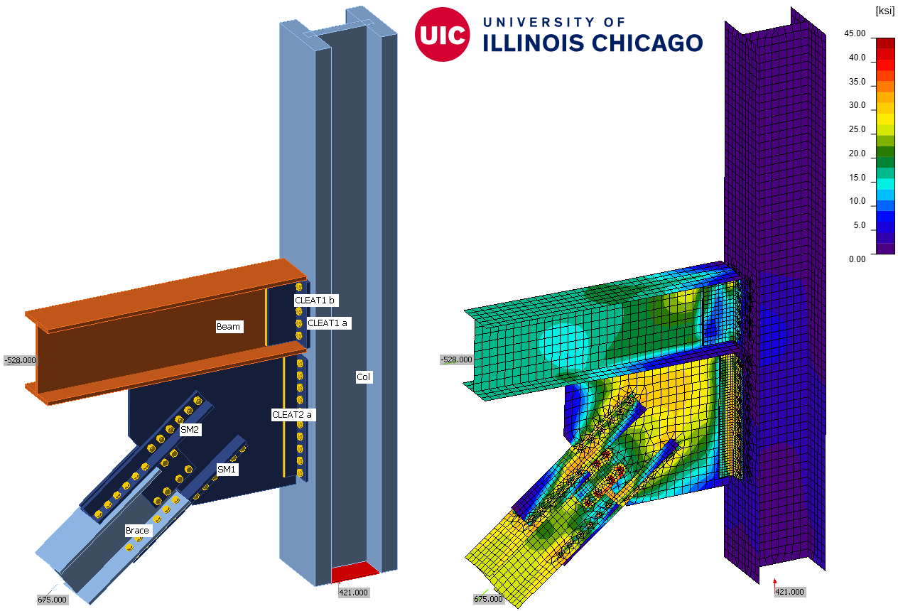
The example uses the sections and dimensions shown in Figures 1 and 2 and as follows. The brace is W12x87 (ASTM A992), beam W18x106 (ASTM A992), column W14x605, gusset plate ¾” (ASTM A36), connecting angles L4x4x3/4 between brace and gusset plate (ASTM A36), connecting angles to column L5x3 ½ x 5/8, 3/8” splice plates (ASTM A36), connecting angles to beam L8x6x7/8 (ASTM A36), 7/8” ASTM A325 bolts and ASTM E70XX weld.

Figure 1. Brace Connection at beam-column connection in a braced frame – Geometry

Figure 2. Brace Connection at beam-column connection in a braced frame – Full Design
The results of the analytical solution are represented by the comparison table for the different limit states shown below. The limit states that should be considered for this connection are as follows and the comparison of the capacities of the different limit states is shown in Table 1.
- Bolt shear at brace to gusset connection
- Tension Yielding of Angles
- Tension Rupture of Angles
- Block Shear Rupture of Angles
- Yielding of splice connecting brace to gusset plate
- Rupture of splice connecting brace to gusset plate
- Block shear of splice connecting brace to gusset plate
- Yielding of Brace
- Rupture of Brace
- Block Shear Rupture of Gusset Plate
- Tension Yielding of Whitmore Section
- Bolt Capacity at Gusset-Column Connection – shear and tension
- Bolt Capacity at Gusset-Column Connection – bolt bearing
- Prying Action on Double Angle
- Shear Yielding of Angles at Gusset-column connection
- Shear Rupture of Angles at Gusset-column connection
- Block Shear Strength at Angles at the Gusset-Column Connection
- Tension Yielding and Shear Yielding of Plate at Gusset-Beam Connection
- Weld between Gusset plate and beam bottom flange
- Web Local Yielding & Crippling of Beam
- Beam to Column Connection
- Beam to Column Connection, Bolt Strength & Weld
Table 1. Limit States checked by AISC
| Limit state | AISC |
| Bolt shear at brace to gusset connection | \(\phi\)rnt = 40.59 kips \(\phi\)rnv = 24.35 kips |
| Tension Yielding of Angles | \(\phi\)Rn = 705 kips |
| Tension Rupture of Angles | \(\phi\)Rn = 746 kips |
| Block Shear Rupture of Angles | \(\phi\)Rn = 932 kips |
| Yielding of splice connecting brace to gusset plate | \(\phi\)Rn = 219 kips |
| Rupture of splice connecting brace to gusset plate | \(\phi\)Rn = 228 kips |
| Block shear of splice connecting brace to gusset plate | \(\phi\)Rn = 175 kips |
| Block shear of brace web | \(\phi\)Rn = 216 kips |
| Yielding of Brace | \(\phi\)Rn = 1152 kips |
| Rupture of Brace | \(\phi\)Rn = 1040 kips |
| Block Shear Rupture of Gusset Plate | \(\phi\)Rn = 945 kips |
| Tension Yielding of Whitmore Section | \(\phi\)Rn = 855 kips |
| Bolt Capacity at Gusset-Column Connection – shear and tension | \(\phi\)Rn = 30.39 kips |
| Bolt Capacity at Gusset-Column Connection – bolt bearing | \(\phi\)rn = 33.64 kips |
| Prying Action on Double Angle | See appendix for calculations |
| Shear Yielding of Angles at Gusset-column connection | \(\phi\)Rn = 810 kips |
| Shear Rupture of Angles at Gusset-column connection | \(\phi\)Rn = 652 kips |
Block Shear Strength at Angles at the Gusset-Column Connection | \(\phi\)Rn = 658 kips |
| Tension Yielding and Shear Yielding of Plate at Gusset-Beam Connection | \(\phi\)Rn = 21.6 ksi |
| Weld between Gusset plate and beam bottom flange | \(\phi\)Rn = 12.024 kips |
| Web Local Yielding of Beam | \(\phi\)Rn = 1338 kips Compared to force in beam equals 152 kips |
| Web Local Crippling of Beam | \(\phi\)Rn = 852 kips Compared to force in beam equals 152 kips |
| Beam to Column Connection Bolt shear | \(\phi\)rnv = 24.33 kips |
| Beam to Column Connection, Weld strength | \(\phi\)Rn = 8.32 kips |
The governing component of this connection is bolt shear between the gusset plate and the brace with load resistance \(\phi\)Rn = 681 kips > Pu = 675 kips (utilization 99%). The next critical is tension yielding of the connecting angles between the brace flange and the gusset plate with the load resistance of \(\phi\)Rn =705 kips > Pu = 675 kips (utilization 96%) and tension rupture of the angles with \(\phi\)Rn =746 kips > Pu = 675 kips (Utilization 90%).
Resistance by CBFEM
The overall check of the connection is verified as shown in Figures 3 and 4. The check shows that the connection just barely fails according to the CBFEM. It can be concluded that the CBFEM is capable of predicting the actual behavior and failure modes of the braced frame connections presented herein. Failure in members and plates due to yielding and rupture limit states is measured based on a 5% plastic strain limit. The figure below shows that the plastic strain is 2.4% which is less than the 5% plastic strain limit. The connection presented includes elements that are welded and others that are bolted. It can be seen that the weld check utilization is 94.9% and is based on the AISC 360-16 specification. Both AISC and CBFEM give the same results for the weld check. The bolt shear check is in agreement in both AISC 360-16 specification and CBFEM. The bolt bearing check in CBFEM is considered for each bolt individually not for the whole connection, which would result in safer and more conservative results than AISC by 2% in this case.

Figure 3. Overall solution of the connection
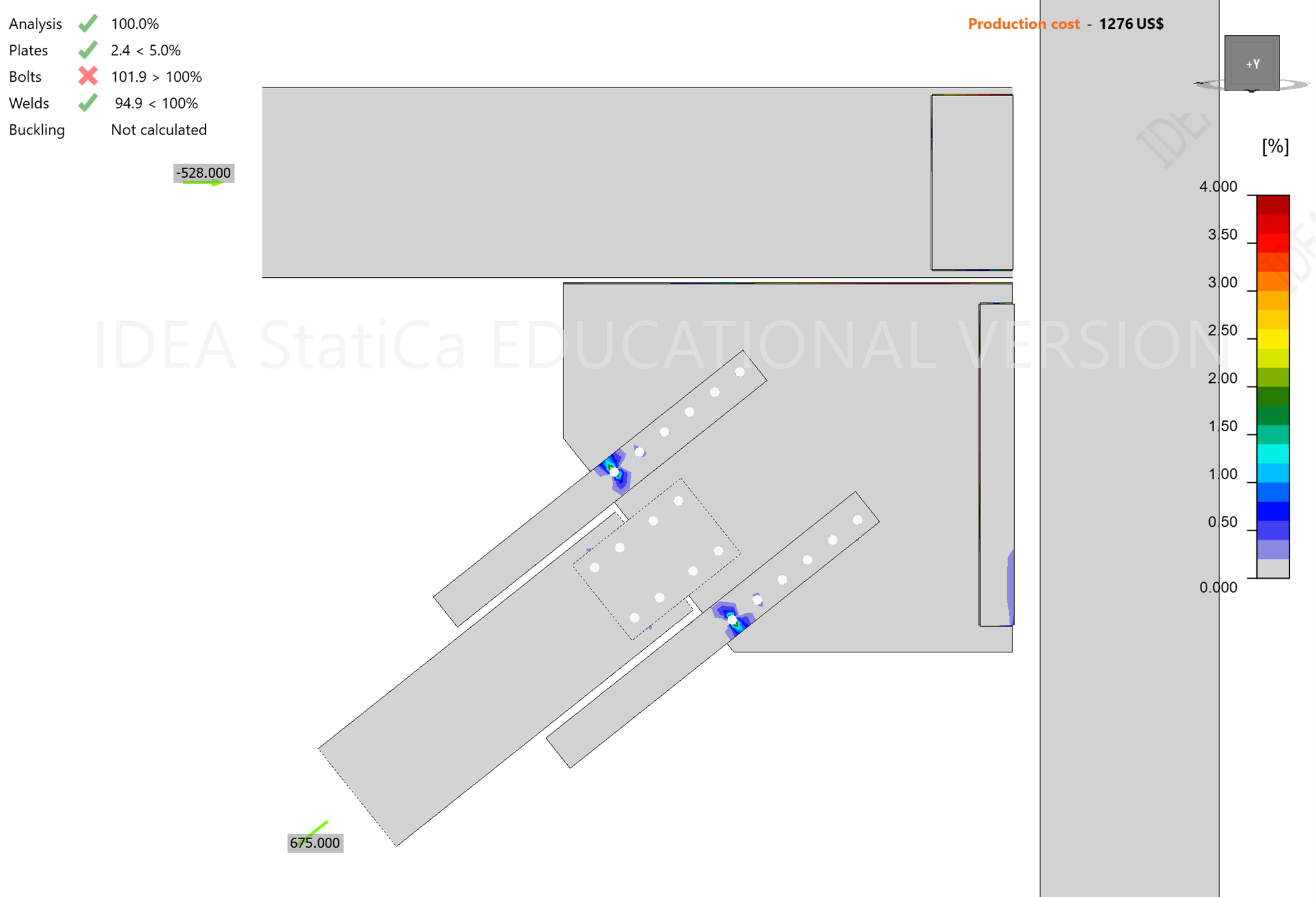
Figure 4. Plastic strains in the overall solution of the connection
Parametric study
The results were obtained using the various limit states per the AISC procedure. These limit states were investigated individually per CBFEM and the capacities were reported accordingly. Bolt limit states including bolt shear, bolt tension, combined bolt shear and tension and bolt bearing are accurate. For the tension yielding, tension rupture, shear yielding and shear rupture limit states, they are found separately. The plastic strain starts at the bolt holes; these stresses are based on von Mises stresses which is a combination of normal and shear stresses. Figure 5 shows the stress distribution in the angles connecting the brace to the gusset plate. CBFEM results show that the plastic strain in the angles is exceeded at a load (780 kips) higher than the originally applied (675 kips) and noted as the failure load for the limit states in the angles. This load is in agreement with the AISC 360-16 requirements as shown in Table 1 for tension rupture of the angles.

Figure 5. Plastic strains in angles connecting the brace to the gusset plate
The block shear limit state can be observed in some members and not in some others. Examples of these two cases are shown in Figures 6, 7 and 8. Figure 6 shows that the stresses are increased around the hole without extending to the adjacent holes, This is in accordance with AISC 360-16 where governing failure mode of the angles is tensile rupture. Figure 7 shows that block shear can be observed accurately in the gusset plate which is also in agreement with AISC 360-16 as shown in Table 1. Figure 8 shows the block shear rupture for the splice plate connecting the brace web to the gusset plate; which is in agreement with the AISC 360-16 specifications and the capacity shown in Table 1.

Figure 6. Plastic strains in angles connecting the brace to the gusset plate at high loads to investigate block shear limit state in the angles

Figure 7. Plastic strains in the gusset plate to investigate block shear limit state
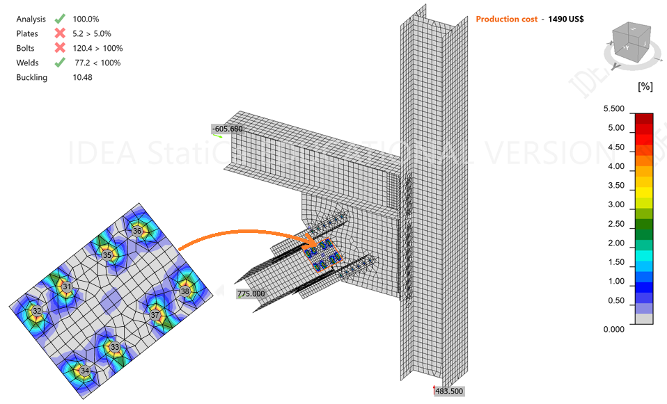
Figure 8. Plastic strains in the splice plate to investigate block shear limit state
The brace rupture failure mode occurs in the web and in the flange as shown in Figures 9 and 10. The brace failure loads are in agreement with AISC 360-16 as presented in Table 1.

Figure 9. Plastic strains in the brace web
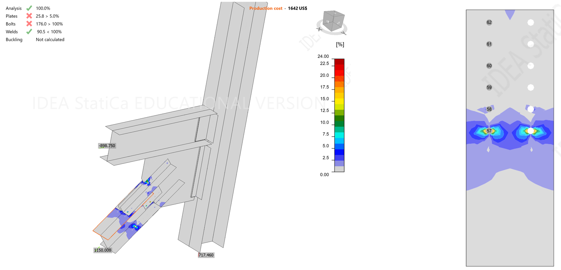
Figure 10. Plastic strains in the brace flange
The AISC specifications require checking yielding at the Whitmore section on the gusset plate. Figure 11 shows the plastic strain distribution in the gusset plate at the failure load for yielding at the Whitmore section per AISC specifications. It is obvious that rupture along the bolt lines would occur before yielding of the gusset plate and as observed in the yielding and rupture capacities in Table 1.
Prying action is another limit state that is required per the AISC specifications; the prying action limit states are taken into consideration in CBFEM by the additional tension forces applied to the bolts.

Figure 11. Plastic strains in the gusset plate at 850 kip load
In investigating the limit states in the angles connecting the gusset plates to the column flange, the capacities for shear yielding, shear rupture in combination with tension rupture and tension yielding are shown in Figure 12. As discussed above, rupture along the bolt line was observed and as the load is increased, the stresses increase along the bolt line without clear observation of the block shear in the angles; this is expected as shear rupture along the bolt line is expected to happen before block shear rupture. The Figure also shows yielding in the gross part of the angle.

Figure 12. Plastic strains in the angles connecting the gusset plate to the column flange
Beam web local and shear yielding would occur at a large load compared to the applied load. Almost all limit states in this connection would occur before these two limit states which typically do not control the design. If needed these limit states can be checked using the AISC specifications using the procedure presented in the appendix for beam web local and shear yielding.
Beam web crippling would occur after yielding and at high loads, therefore, the model may not converge under such high loads and would not be able to capture this failure mode. If the crippling capacity is needed, it can be calculated per the AISC specifications using the procedure presented in the appendix.
Summary
It can be concluded that the CBFEM is capable of predicting the actual behavior and failure mode of the braced frame connection presented herein.
The various limit states were investigated carefully by performing a parametric study which resulted in obtaining the capacity for each limit state using CBFEM. The weld capacity for the weld between the gusset and the beam bottom flange and between the beam and the column are in agreement in both AISC and CBFEM. Bolt limit states including bolt shear, bolt tension, combined bolt shear and tension and bolt bearing in AISC are in agreement with CBFEM. The plates’ limit states including yielding, rupture in tension and in shear are based on 5% plastic strain limit according to CBFEM. The tension rupture in the angles is in agreement per AISC and CBFEM with less than 10% difference in the capacities. For the block shear limit state, it can be observed in the gusset plate and in the web connecting plate, but not in other plates such as the angles connecting the gusset plate to the column; this is because shear and tension rupture of the angles precede block shear rupture. Prying action limit state, required by AISC specifications; is taken into consideration in CBFEM by the additional tension forces applied to the bolts. Beam web buckling, web crippling and shear yielding would occur at high loads and the model would not converge at such high loads; all other limit states would occur before these limit states. If necessary, these limit states can be checked per the AISC specifications as shown in the Appendix. Buckling limit state of the gusset plate was not observed as a limit state in AISC and in CBFEM.
Benchmark case
Input
Beam cross-section
- W18X106
- Steel ASTM A992
Braces cross-section
- W27X84
- Steel ASTM A992
Column cross-section
- W14X605
- Steel ASTM A992
Gusset plate
- Thickness 3/4 in.
- Steel ASTM A36
Splice plate connecting beam web to gusset plate
- 2-3/8”x9” plates
- Steel ASTM A36
Angles connecting brace to gusset plate
- 4-L4x4x3/4
- Steel ASTM A36
Angles connecting gusset to column
- 2-L5x3 ½x5/8
- Steel ASTM A36
Angles connecting beam to column
- 2-L8x6x7/8
- Steel ASTM A36
Loading
- Axial force N = 675 kips in tension
Output
- Weld 94.9%
- Bolts 101.9%
- Plastic strain 2.4% < 5%
- Buckling factor 12.01
References
AISC. (2016). Specification for Structural Steel Buildings. American Institute of Steel Construction, Chicago, Illinois.
AISC. (2017). Steel Construction Manual, 15th Edition. American Institute of Steel Construction, Chicago, Illinois.
AISC. (2015). Design Guide 29, Vertical Bracing Connections-Analysis and Design, American Institute of Steel Construction, Chicago, Illinois.
Attached Downloads
- Example 3 - corner connection.pdf (PDF, 1.7 MB)