Brace Connection at beam-column connection in a braced frame – Double Angle Brace (AISC)
This verification example was prepared by Mahamid Mustafa in a joint project of The University of Illinois in Chicago and IDEA StatiCa.
Description
The objective of this example is verification of the component-based finite element method (CBFEM) of a Brace Connection at a beam-column connection in a braced frame with the AISC design procedure. The study is prepared for the size of the brace, beam, column, connecting angles, geometry, the thickness of the plate, bolts and welds. In this study, ten components are examined: brace, beam flange and web, column flange and web, connecting angles, gusset plate, splice plates between brace and gusset plate, connecting angles to column, connecting angles to beam, bolts and welds. All components are designed according to AISC -360-16 specifications. The connection presented is taken from AISC Design Guide 29.
Verification of resistance
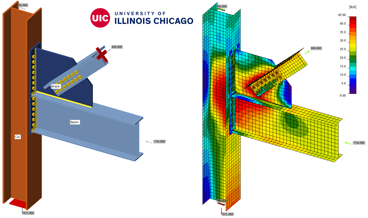
The example used uses the sections and dimensions shown in Figure 1 and are as follows. Brace is 2L8×6×l LLBB (ASTM A36), beam W21×83 (ASTM A992), column W14×90 (ASTM A992), 1” thick gusset plate (ASTM A36), ¾” thick end plate connecting gusset plate to column flange (ASTM A572 Gr. 50), 7/8” ASTM A490-X bolts and ASTM E70XX weld.

Figure 1. Brace Connection at beam-column connection in a braced frame – Geometry and Full Design
The results of the analytical solution are represented by the comparison table for the different limit states shown below. The limit states that should be considered for this connection are as follows and the comparison of the capacities of the different limit states is shown in Table 1.
- Bolts at brace to gusset plate
- Tensile yielding on the brace gross section
- Tensile rupture on the brace net section
- Block shear rupture on the brace
- Block shear rupture on the gusset plate
- Bolt bearing on the gusset plate
- Tensile yielding on the Whitmore section of the gusset plate, tensile yielding strength of the gusset plate
- Compression buckling on the Whitmore section of the gusset
- Gusset plate for shear yielding and tensile yielding along the beam flange
- Weld at gusset-to-beam flange connection
- Beam web local yielding
- Beam web local crippling
- Bolts at gusset-to-column connection
- Gusset-to-end plate weld
- Gusset plate tensile and shear yielding at the gusset-to-end-plate interface
- Prying action on bolts at the end plate
- Bolt bearing at bolt holes on end plate
- Block shear rupture of the end plate
- Prying action on column flange
- Bearing on column flange
- Bolts at beam-to-column connection
- Beam web-to-end plate weld
- Prying action on bolts and end plate
- Prying action on column flange
- Beam shear strength
- Column shear strength
Table 1. Limit States checked by AISC
| Limit state | AISC |
Bolts at brace to gusset plate | \(\phi\)rnt = 51 kips \(\phi\)rnv = 37.9 kips |
| Tensile yielding on the brace gross section | \(\phi\)Rn = 849 kips |
| Tensile rupture on the brace net section | \(\phi\)Rn = 877 kips |
| Block shear rupture on the brace | \(\phi\)Rn = 936 kips |
| Block shear rupture on the gusset plate | \(\phi\)Rn = 855 kips |
Bolt bearing on the gusset plate | Single bolt: \(\phi\)Rn_edge = 60.3 kips \(\phi\)Rn_edge = 75.8 kips Connection: \(\phi\)Rn = 1029.9 kips |
Tensile yielding on the Whitmore section of the gusset plate Tensile yielding strength of the gusset plate | \(\phi\)Rn = 968 kips |
| Compression buckling on the Whitmore section of the gusset | \(\phi\)Rn = 940.5 kips |
Gusset plate for shear yielding and tensile yielding along the beam flange | Shear yielding \(\phi\)Rn = 940 kips Tension Yielding \(\phi\)Rn = 1416 kips |
Weld at gusset-to-beam flange connection | 7/16” weld, required 6.2/16” weld |
Beam web local yielding | \(\phi\)Rn = 896.6 kips Compared to Vbeam = 269.2 kips |
Beam web local crippling | \(\phi\)Rn = 765.4 kips Compared to Vbeam = 269.2 kips |
Bolts at gusset-to-column connection | \(\phi\)Rn = 37.2 kips combined shear and tension |
| Gusset-to-end plate weld | 6/16” weld, required 5.1/16” |
Gusset plate tensile and shear yielding at the gusset-to-end-plate interface | Tensile yielding: \(\phi\)Rn = 1070.3 kips, compared to Hcolumn = 176.1 kips Shear Yielding: \(\phi\)Rn = 713.5 kips, compared to Vcolumn = 301.9 kips |
| Prying action on bolts at the end plate | \(\phi\)Rn =24.2 kips |
Bolt bearing at bolt holes on end plate | \(\phi\)Rn =37.9 kips Bolt shear governs |
Block shear rupture of the end plate | \(\phi\)Rn = 591 kips Compared to Vcolumn = 301.9 kips |
| Prying action on column flange | \(\phi\)Rn =17.8 kips |
| Bearing on column flange | tf = 0.7 in. > tPL = 0.625 in. does not govern |
| Bolts at beam-to-column connection | \(\phi\)Rn =30.5 kips |
Beam web-to-end plate weld | 7/16” weld, required 6.4/16” |
| Prying action on bolts and end plate | \(\phi\)Rn =20.3 kips |
| Prying action on column flange | \(\phi\)Rn =17.8 kips |
| Beam shear strength | \(\phi\)Rn =330.6 kips Compared to Hucolumn = 319.2 kips |
| Column shear strength | \(\phi\)Rn = 184.8 kips Compared to Hucolumn = 176.1 kips |
The governing component of this connection is tension yielding of the brace followed by tension rupture of the brace. The detailed calculation is in the attachment.
Resistance by CBFEM
The overall check of the connection is verified as shown in Figures 2 and 3. In this connection, there are two load cases, one in compression and one in tension. The compression load case converged completely to 100% of the applied load, while the tension load case converged to 91% of the load which gives conservative results compared to AISC. It can be concluded that the CBFEM is capable of predicting the actual behavior and failure modes of the braced frame connections presented herein. Failure in members and plates due to yielding and rupture limit states is measured based on a 5% plastic strain limit. The figure below shows that the plastic strain is 3.6% at 91% of the load which is less than the 5% plastic strain limit. The connection presented includes elements that are welded and others that are bolted. It can be seen that the weld check utilization is 94.9% and is based on the AISC 360-16 specification. Both AISC and CBFEM give the same results for the weld check. The bolt shear check is in agreement in both AISC 360-16 specification and CBFEM which is based on the compression load, which converged to 100%. Similarly, the bolt bearing check in CBFEM and AISC are in agreement per a single bolt check; it is worth mentioning that CBFEM checks the bolts individually for bearing and the utilization ratio is based on that, where the utilization ratio per AISC is based on the summation of the bearing capacities of all the bolts; this would result in CBFEM to be safer and slightly more conservative results than AISC.

Figure 2. Overall solution of the connection
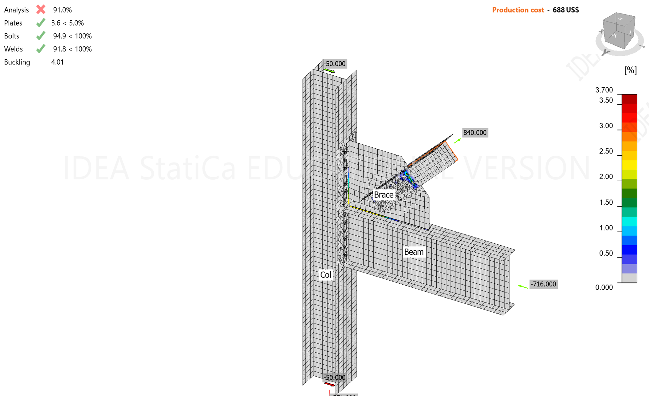
Figure 3. Plastic strains in the overall solution of the connection
The results were obtained using the various limit states per the AISC procedure. These limit states were investigated individually per CBFEM and the capacities were reported accordingly. Bolt limit states including bolt shear, bolt tension, combined bolt shear and tension and bolt bearing are accurate. For the tension yielding, tension rupture, shear yielding and shear rupture limit states, they are found separately. The plastic strain starts at the bolt holes; these stresses are based on von Mises stresses which is a combination of normal and shear stresses. Figure 4 shows the stress distribution in the angles connecting the brace to the gusset plate. CBFEM results show tension yielding and tension rupture would occur at the first row of bolts which is in agreement with AISC solution. The capacity in these limit states per AISC (Table 1) is within 3%, and the CBFEM results are within 9% (91% convergence) and provide safer and more conservative results than AISC.

Figure 4. Plastic strains in angles connecting the brace to the gusset plate
The block shear capacity for the brace per AISC occurs at 936 kips per Table 1, which is greater than the capacity of the brace in tension yielding and tension rupture. It has been observed that with increasing load, the plastic strain increases at the first bolt line, where failure would initially occur. The block shear capacity in the gusset plate is 855 kips, which is close to the tension yielding and tension rupture of the brace that controls the design of the connection; as mentioned above, with load increase the plastic strain increases at the first bolt line. Figures 5 and 6 show the concentration of plastic strains at the first bolt line and the block shear path. This is in accordance with AISC 360-16 where governing failure mode of the angles is tensile yielding with a capacity of 849 kips as shown in Table 1.
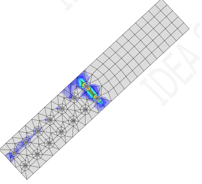
Figure 5. Plastic strains in angles connecting the brace to the gusset plate in the investigation of tension yielding, tension rupture and block shear
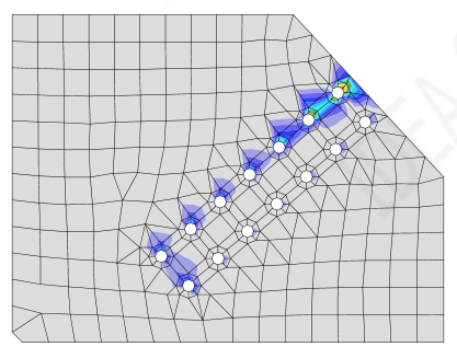
Figure 6. Plastic strains in the gusset plate to investigate block shear limit state
The AISC specifications require checking yielding at Whitmore section on the gusset plate. The AISC capacity for tension yielding at Whitmore section is 968 kips which is higher than the governing failure modes. It is obvious that rupture along the bolt lines would occur before yielding of the gusset plate and as observed in the yielding and rupture capacities in Table 1.
Prying action is another limit state that is required per the AISC specifications; the prying action limit states is taken into consideration in CBFEM by the additional tension forces applied to the bolts.
The compression buckling capacity of the gusset plate per AISC 360-16 specification is 940.5 kips, which is higher than the controlling limit states. The buckling factor obtained by CBFEM is 4.10 for the compression load case. The first mode buckling shape is shown in Figure 7. Both AISC and CBFEM are in agreement in checking the buckling failure mode of the gusset plate.
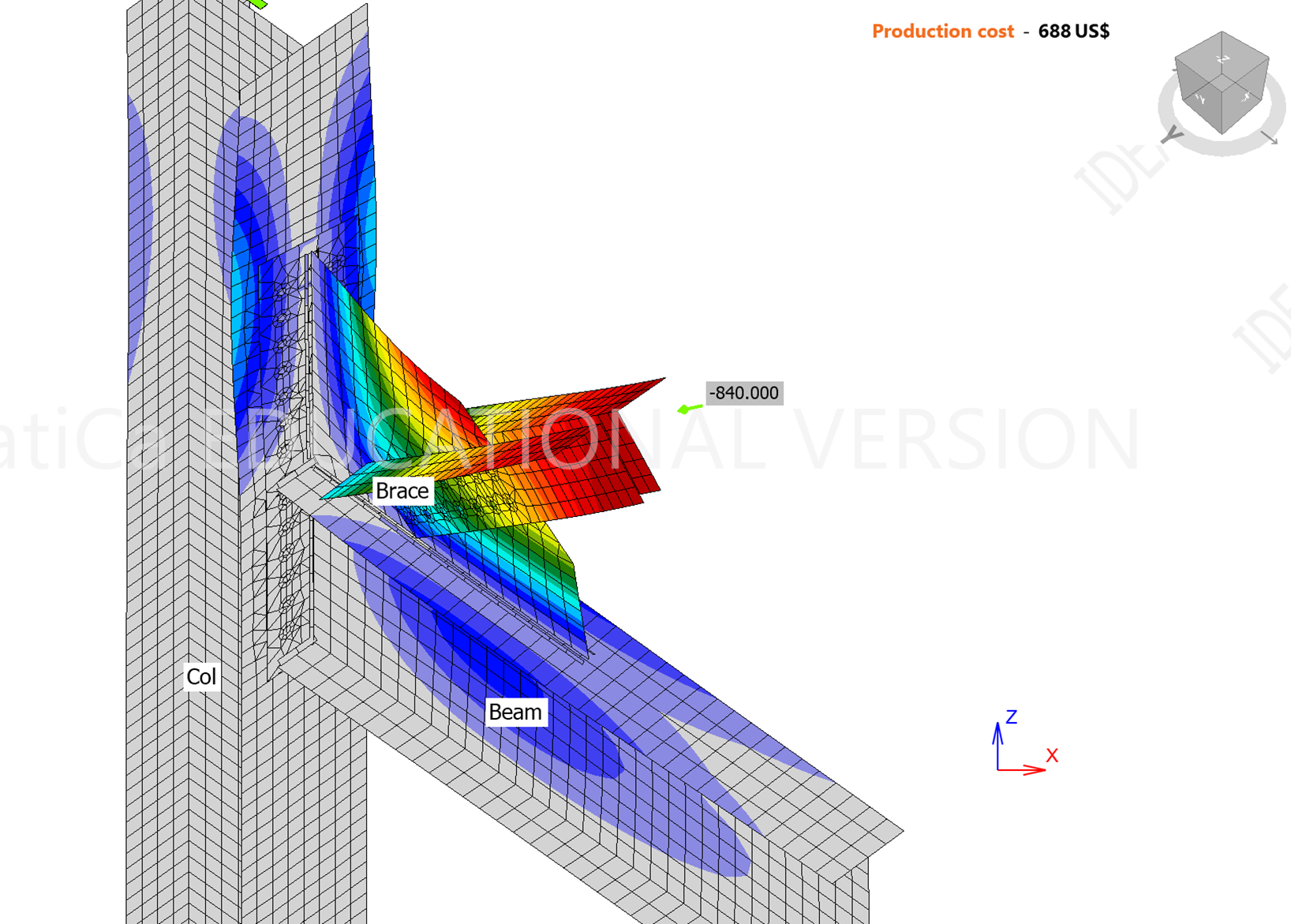
Figure 7. First mode buckling shape
For the combination of shear yielding and tensile yielding along the gusset plate-beam top flange, AISC gives a very small interaction, CBFEM low stresses and zero plastic strains, see Figure 8.

Figure 8. Stress distribution in the connection & top flange and plastic strains at top flange
For the gusset plate tensile and shear yielding at the gusset-to-end-plate interface, the AISC capacity for tension yielding capacity is 1073 kips, compared to applied horizontal force on the column, Hcolumn = 175 kips, and for shear yielding capacity is 713 kips, compared to applied vertical force, Vcolumn = 302 kips. CBFEM gives combined stresses from tension and shear as shown in Figure 9; it is also obvious that there are no plastic strains in the end plate. To investigate this failure mode, a much higher force needs to be applied, at which the model will not converge. The controlling limit states indicated above would occur at a much lower load.

Figure 9. Stress distribution in the connection & end plate and plastic strains in the end plate
Bolt shear and bolt bearing capacity in the end plate and column flange per AISC and CBFEM are in agreement. The block shear rupture capacity for the end plate is 591 kips, compared to the applied force, Vcolumn = 302 kips. Again, to reach the capacity of block shear at the end plate, a much higher force should be applied at which the model will not converge. The controlling limit states occur at a much smaller load than the load that would cause block shear failure at the end plate.
Beam web local buckling and web crippling would occur at a large load compared to the applied load. The beam web local buckling capacity shown in Table 1 is compared to Vbeam =269 kips and the web crippling capacity shown in Table 1 is compared to Vbeam =269 kips. Almost all limit states in this connection would occur before these two limit states which typically do not control the design. If needed these limit states can be checked using the AISC specifications using the procedure presented in the attachment for beam web local and shear yielding.
Beam web crippling would occur after yielding and at high loads, therefore, the model may not converge under such high loads and would not be able to capture this failure mode. If the crippling capacity is needed, it can be calculated per the AISC specifications using the procedure presented in the attachment.
Summary
The connection presented herein has two load cases, tension in the brace and compression in the brace. The load case with compression force in the brace converged to 100% while the load case with the tension force converged to 91%. The connection controlling limit state per AISC, is tension yielding, with a capacity of 849 kips, compared to applied load equals to 840 kips. This means that CBFEM is safer and more conservative by approximately 10% for the tension load case. It can be concluded that the CBFEM is capable of predicting the actual behavior and failure mode of the braced frame connections presented herein. The various limit states were investigated carefully by checking all relevant limit states and comparing the AISC vs. the CBFEM capacities. The weld capacity for the weld between the gusset and the beam top flange, between gusset plate and end plate are in agreement in both AISC and CBFEM. Bolt limit states including bolt shear, bolt tension, combined bolt shear and tension and bolt bearing in AISC are in agreement with CBFEM. The plates’ limit states including yielding, rupture in tension and in shear are based on a 5% plastic strain limit according to CBFEM.
Tension yielding and tension rupture in the brace are in agreement in AISC and CBFEM with approximately 10% difference in the capacities. For the block shear limit state, it can be observed in the gusset plate and in the end plate, but not in other plates such as the brace angles; this is because shear and tension rupture of the angles precede block shear rupture. Prying action limit state, required by AISC specifications, is taken into consideration in CBFEM by the additional tension forces applied to the bolts. Beam web buckling, web crippling and shear yielding would occur at high loads and the model would not converge at such high loads; all other limit states would occur before these limit states. If necessary, these limit states can be checked per the AISC specifications as shown in the attachment. The buckling limit state of the gusset plate was not observed as a limit state in AISC and in CBFEM.
Benchmark case
Input
Beam cross-section
- W21X83
- Steel ASTM A992
Braces cross-section
- 2L8X6X1 LLBB
- Steel ASTM A36
Column cross-section
- W14X90
- Steel ASTM A992
Gusset plate
- Thickness 1 in.
- Steel ASTM A572 Gr. 50
End plate connecting gusset to column
- Thickness 3/4 in.
- Steel ASTM A572 Gr. 50
Loading
- Axial force N = 840 kips in tension and compression
Weld
- Gusset to end plate 3/8” ASTM E70
- Gusset to beam to flange 7/16” ASTM E70
- Beam to end plate 7/16” ASTM E70
Output
- Weld 91.8%
- Bolts 94.9%
- Plastic strain 3.6% < 5%
- Buckling factor 4.01
References
AISC. (2016). Specification for Structural Steel Buildings. American Institute of Steel Construction, Chicago, Illinois.
AISC. (2017). Steel Construction Manual, 15th Edition. American Institute of Steel Construction, Chicago, Illinois.
AISC. (2015). Design Guide 29, Vertical Bracing Connections-Analysis and Design, American Institute of Steel Construction, Chicago, Illinois.
Attached Downloads
- Example 1 (12.06.21).pdf (PDF, 545 kB)