Bolts and preloaded bolts connections
Bolts
In the Component-Based Finite Element Method (CBFEM), the bolt with its behavior in tension, shear, and bearing is the component described by the dependent nonlinear springs. Bolt assembly consists of bolt, washer, and nut and is simulated by a nonlinear spring, rigid body elements and gap elements.
Bolt in tension
The bolt in tension is described by spring with its initial axial stiffness, design resistance, initialization of yielding, and deformation capacity. The initial axial stiffness is derived analytically in the guideline VDI2230 and in Agerskov (1976).
\[D_{Lb} =\frac{L_s+0.4d_b}{EA_{s}}+ \frac{0.85d_b}{EA_{t}}\]
\[A_{pp}=\frac{0.75D_H(L_w-D_H)}{D_{W1}^2-D_{W2}^2}\]
\[A_{P1}=\frac{\pi}{4}(D_H^2-D_{W1}^2)\]
\[A_{P2}=\frac{1}{2}(D_{W2}^2-D_H^2)\tan^{-1}A_{pp}\]
\[A_P=A_{P1}+A_{P2}\]
\[D_{LW}=\frac{L_W}{EA_P}\]
\[k=\frac{1}{D_{LB}+D_{LW}}\]
where:
- \(d_b\) – bolt diameter
- \(D_H\) – bolt head diameter
- \(D_{W1}\) – washer inner diameter
- \(D_{W2}\) – washer outer diameter
- \(L_W\) – sum of washer thicknesses
- \(L_s\) – bolt grip length
- \(A_{s}\) – bolt gross area
- \(A_{t}\) – bolt tensile stress area
- \(E\) – Young's modulus of elasticity
The model corresponds to experimental data; see Gödrich et al. (2014). For the initialization of yielding and deformation capacity, it is assumed that plastic deformation occurs in the threaded part of the bolt shank only.
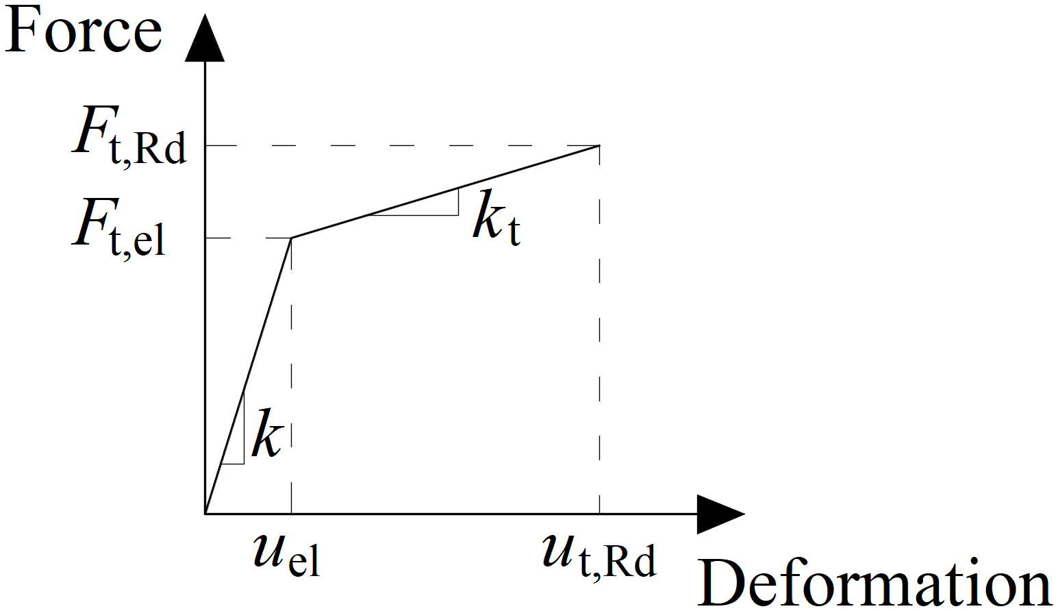
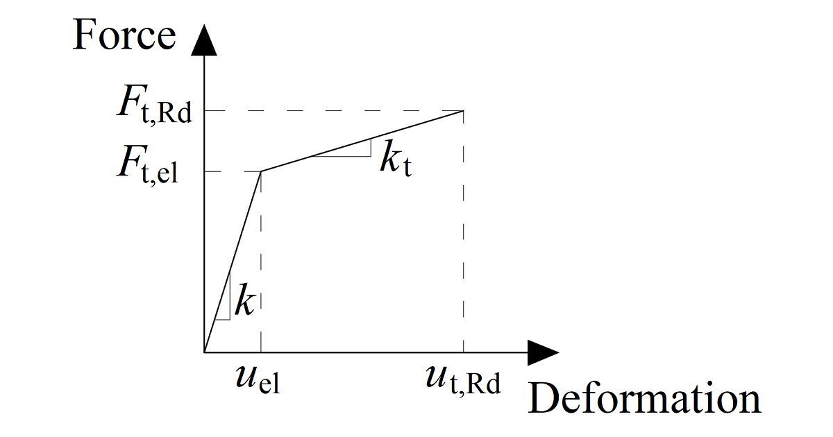
Force-deformation diagram for the bearing of the plate
The force-deformation diagram is constructed using the following equations:
Plastic stiffness:
\[ k_t = c_1 k \]
Force at the elastic limit:
\[ F_{t,el} = \frac{F_{t,Rd}}{c_1 c_2 - c_1 +1} \]
Deformation at elastic limit:
\[ u_{el} = \frac{ F_{t,el} }{k} \]
Deformation at plastic limit:
\[ u_{t,Rd} = c_2 u_{el} \]
\[ c_1 = \frac{f_{ub} - f_{yb}}{\frac{1}{4} A E - f_{yb}} \]
\[ c_2 = \frac{AE}{4 f_{yb}} \]
where:
- \(F_{t,Rd}\) – bolt design resistance in tension
- \(f_{yb}\) – bolt yield strength
- \(f_{ub}\) – bolt ultimate strength
- \(A\) – elongation after fracture
Bolt in shear
Only the compression force is transferred from the bolt shank to the plate in the bolt hole. It is modeled by interpolation links between the shank nodes and holes edge nodes. The deformation stiffness of the shell element modeling the plates distributes the forces between the bolts and simulates the adequate bearing of the plate.
Bolt holes are considered as standard (default) or slotted (can be set in plate editor). Bolts in standard holes can transfer shear force in all directions, bolts in slotted holes have one direction excluded and can move in this selected direction freely.
The initial stiffness and the design resistance of a bolt in shear is defined by following formulas:
\[k_{el}=\frac{1}{\frac{1}{k_{11}}+\frac{1}{k_{12}}}\]
\[k_{11} = \frac{8d_b^2f_{ub}}{d_{M16}}\]
\[k_{12}=12k_td_bf_{up}\]
\[k_t=\min \left ( 2.5,\, \frac{1.5t_{min}}{d_{M16}} \right ) \]
\[k_{pl}=\frac{k_{el}}{1000}\]
where:
- \(d_b\) – bolt diameter
- \(f_{ub}\) – bolt ultimate strength
- \(d_{M16}=16 \textrm{ mm}\) – diameter of the reference bolt M16
- \(f_{up}\) – ultimate strength of the connected plate
- \(t_{min}\) – minimum thickness of the connected plate
The spring representing the bolt in shear has bi-linear force deformation behavior. Initialization of yielding is expected at:
\[F_{V,el}=0.999 F_{V,Rd}\]
Deformation capacity is considered as:
\[\delta_{pl}=\delta_{el}\]
where:
- \(F_{V,el}\) – bolt in shear elastic resistance
- \(F_{V,Rd}\) – bolt in shear resistance
- \(\delta_{el}\) – bolt in shear elastic deformation
Interaction between tension and shear
Interaction of the axial and the shear force can be introduced directly in the analysis model. The distribution of forces reflects the reality better (see enclosed diagram). Bolts with a high tensile force take less shear force and vice versa.
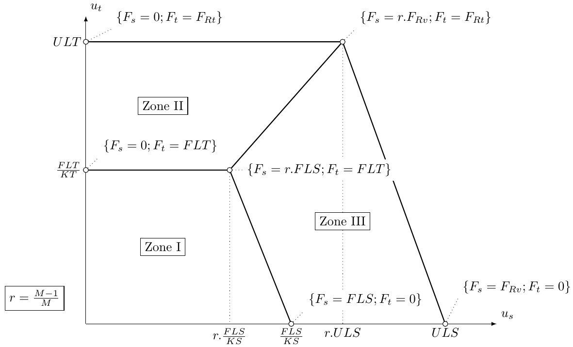
Example of the interaction of axial and shear force (EC)
Preloaded bolts
Preloaded bolts are used in cases when minimization of deformation is needed. The tension model of a bolt is the same as for standard bolts. The shear force is not transferred via bearing but via friction between gripped plates.
The design slip resistance of a preloaded bolt is affected by an applied tensile force.
IDEA StatiCa Connection checks the pre-slipping limit state of preloaded bolts. If there is a slipping effect, bolts do not satisfy the check. Then the post-slipping limit state should be checked as a standard bearing check of bolts where bolt holes are loaded in bearing and bolts in shear.
The user can decide which limit state will be checked. Either it is resistance to major slip or post-slipping state in shear of bolts. Both checks on one bolt are not combined in one solution. It is assumed that the bolt has a standard behavior after a major slip and can be checked by the standard bearing procedure.
The moment load of connection has a small influence on the shear capacity. Nevertheless, a friction check on each bolt simply is solved separately. This check is implemented in FEM component of the bolt. There is no information in a general way on whether the external tension load of each bolt is from the bending moment or from the tension load of the connection.
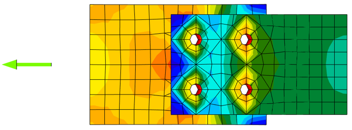
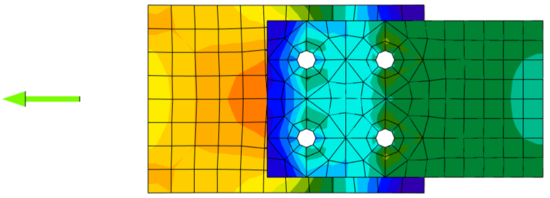
Stress distribution in standard shear bolt connection
Stress distribution in slip-resistant shear bolt connection