Assemblages par boulons et boulons précontraints
Boulons
Dans la Méthode des Éléments Finis basée sur les composants (CBFEM), le boulon avec son comportement en traction, cisaillement et appui est le composant décrit par des ressorts non linéaires dépendants. L'assemblage boulon comprend le boulon, la rondelle et l'écrou, et est simulé par un ressort non linéaire, des éléments de corps rigide et des éléments de contact.
Boulon en traction
Le boulon en traction est décrit par un ressort avec sa rigidité axiale initiale, sa résistance de calcul, l'initialisation de la plastification et la capacité de déformation. La rigidité axiale initiale est dérivée analytiquement dans la directive VDI2230 et dans Agerskov (1976).
\[D_{Lb} =\frac{L_s+0.4d_b}{EA_{s}}+ \frac{0.85d_b}{EA_{t}}\]
\[A_{pp}=\frac{0.75D_H(L_w-D_H)}{D_{W1}^2-D_{W2}^2}\]
\[A_{P1}=\frac{\pi}{4}(D_H^2-D_{W1}^2)\]
\[A_{P2}=\frac{1}{2}(D_{W2}^2-D_H^2)\tan^{-1}A_{pp}\]
\[A_P=A_{P1}+A_{P2}\]
\[D_{LW}=\frac{L_W}{EA_P}\]
\[k=\frac{1}{D_{LB}+D_{LW}}\]
où :
- \(d_b\) – diamètre du boulon
- \(D_H\) – diamètre de la tête du boulon
- \(D_{W1}\) – diamètre intérieur de la rondelle
- \(D_{W2}\) – diamètre extérieur de la rondelle
- \(L_W\) – somme des épaisseurs des rondelles
- \(L_s\) – longueur de serrage du boulon
- \(A_{s}\) – section brute du boulon
- \(A_{t}\) – section résistante en traction du boulon
- \(E\) – module d'élasticité de Young
Le modèle correspond aux données expérimentales ; voir Gödrich et al. (2014). Pour l'initialisation de la plastification et la capacité de déformation, il est supposé que la déformation plastique se produit uniquement dans la partie filetée de la tige du boulon.
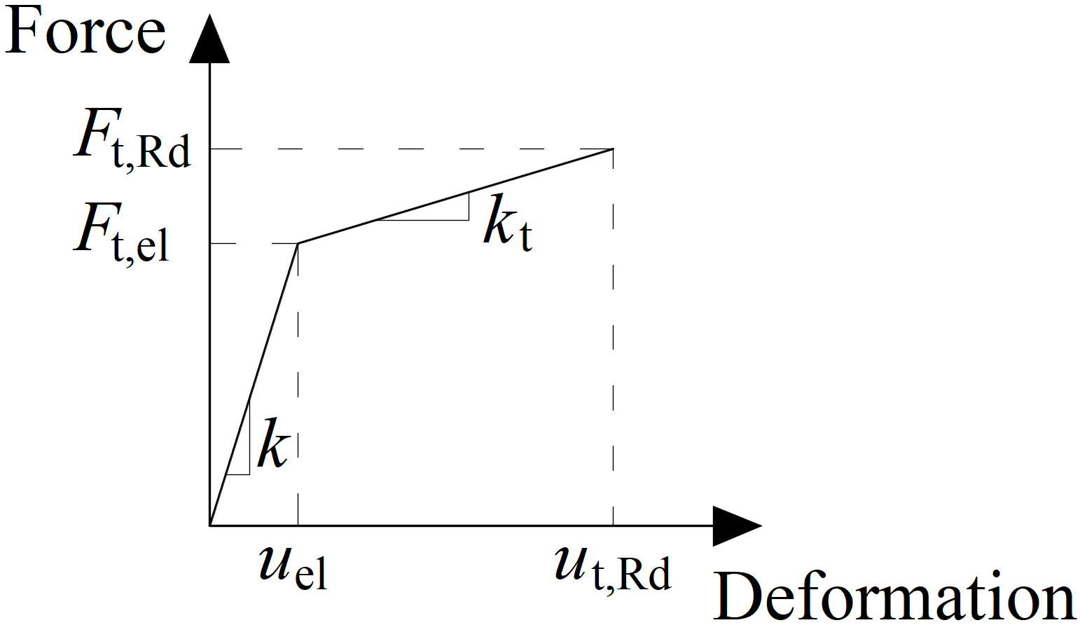
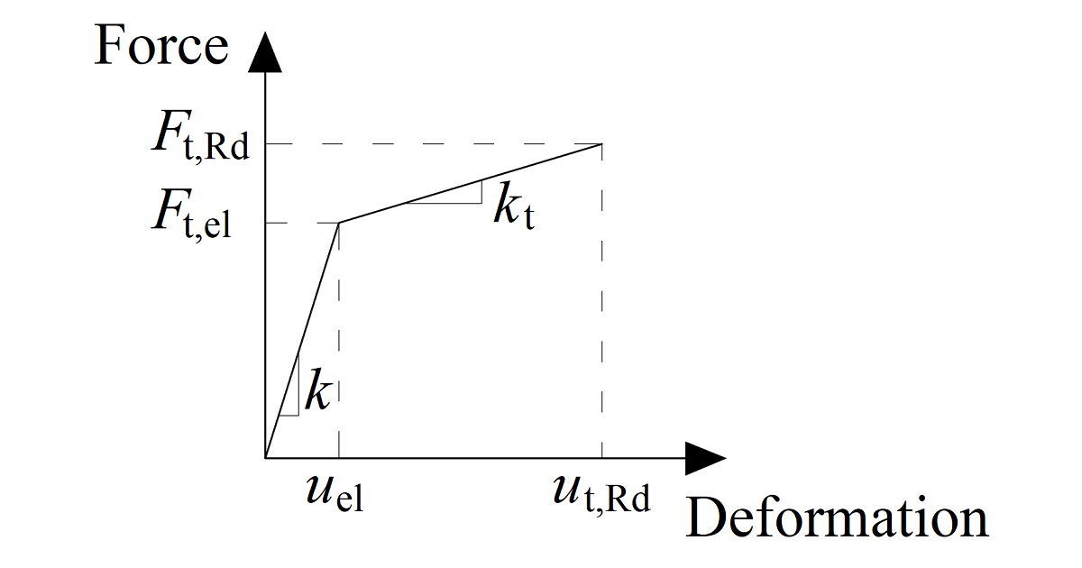
Diagramme force-déformation pour l'appui de la plaque
Le diagramme force-déformation est construit à l'aide des équations suivantes :
Rigidité plastique :
\[ k_t = c_1 k \]
Force à la limite élastique :
\[ F_{t,el} = \frac{F_{t,Rd}}{c_1 c_2 - c_1 +1} \]
Déformation à la limite élastique :
\[ u_{el} = \frac{ F_{t,el} }{k} \]
Déformation à la limite plastique :
\[ u_{t,Rd} = c_2 u_{el} \]
\[ c_1 = \frac{f_{ub} - f_{yb}}{\frac{1}{4} A E - f_{yb}} \]
\[ c_2 = \frac{AE}{4 f_{yb}} \]
où :
- \(F_{t,Rd}\) – valeur de calcul de la résistance du boulon en traction
- \(f_{yb}\) – limite d'élasticité du boulon
- \(f_{ub}\) – résistance ultime du boulon
- \(A\) – allongement après rupture
Boulon en cisaillement
Seul l'effort de compression est transmis de la tige du boulon à la plaque dans le trou de boulon. Il est modélisé par des liens d'interpolation entre les nœuds de la tige et les nœuds du bord des trous. La rigidité de déformation de l'élément coque modélisant les plaques distribue les efforts entre les boulons et simule l'appui adéquat de la plaque.
Les trous de boulons sont considérés comme standard (par défaut) ou oblongs (peut être défini dans l'éditeur de plaque). Les boulons dans les trous standard peuvent transmettre un effort de cisaillement dans toutes les directions ; les boulons dans les trous oblongs ont une direction exclue et peuvent se déplacer librement dans cette direction sélectionnée.
La rigidité initiale et la résistance de calcul d'un boulon en cisaillement sont définies par les formules suivantes :
\[k_{el}=\frac{1}{\frac{1}{k_{11}}+\frac{1}{k_{12}}}\]
\[k_{11} = \frac{8d_b^2f_{ub}}{d_{M16}}\]
\[k_{12}=12k_td_bf_{up}\]
\[k_t=\min \left ( 2.5,\, \frac{1.5t_{min}}{d_{M16}} \right ) \]
\[k_{pl}=\frac{k_{el}}{1000}\]
où :
- \(d_b\) – diamètre du boulon
- \(f_{ub}\) – résistance ultime du boulon
- \(d_{M16}=16 \textrm{ mm}\) – diamètre du boulon de référence M16
- \(f_{up}\) – résistance ultime de la plaque assemblée
- \(t_{min}\) – épaisseur minimale de la plaque assemblée
Le ressort représentant le boulon en cisaillement a un comportement force-déformation bilinéaire. L'initialisation de la plastification est attendue à :
\[F_{V,el}=0.999 F_{V,Rd}\]
La capacité de déformation est considérée comme :
\[\delta_{pl}=\delta_{el}\]
où :
- \(F_{V,el}\) – résistance élastique du boulon en cisaillement
- \(F_{V,Rd}\) – résistance du boulon en cisaillement
- \(\delta_{el}\) – déformation élastique du boulon en cisaillement
Interaction entre traction et cisaillement
L'interaction de l'effort axial et de l'effort de cisaillement peut être introduite directement dans le modèle d'analyse. La distribution des efforts reflète mieux la réalité (voir le diagramme ci-joint). Les boulons soumis à un effort de traction élevé reprennent moins d'effort de cisaillement et vice versa.
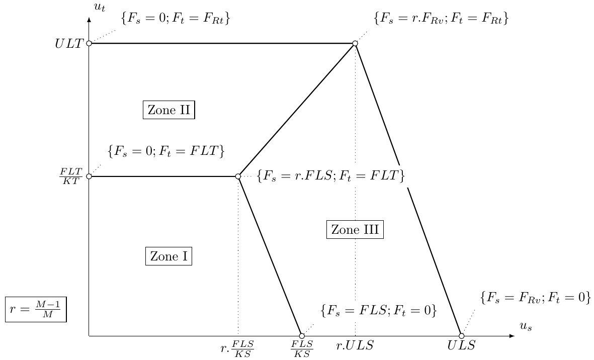
Exemple d'interaction entre effort axial et effort de cisaillement (EC)
Boulons précontraints
Les boulons précontraints sont utilisés dans les cas où une minimisation des déformations est nécessaire. Le modèle de traction d'un boulon est identique à celui des boulons standard. L'effort de cisaillement n'est pas transmis par appui mais par friction entre les plaques serrées.
La résistance de calcul au glissement d'un boulon précontraint est affectée par un effort de traction appliqué.
IDEA StatiCa Connection vérifie l'état limite de pré-glissement des boulons précontraints. En cas d'effet de glissement, les boulons ne satisfont pas la vérification normative. L'état limite post-glissement doit alors être vérifié comme une vérification d'appui standard des boulons, où les trous de boulons sont chargés en appui et les boulons en cisaillement.
L'utilisateur peut décider quel état limite sera vérifié : soit la résistance au glissement majeur, soit l'état post-glissement en cisaillement des boulons. Les deux vérifications sur un même boulon ne sont pas combinées dans une seule solution. Il est supposé que le boulon a un comportement standard après un glissement majeur et peut être vérifié par la procédure d'appui standard.
Le chargement en moment de l'assemblage a une faible influence sur la capacité de cisaillement. Néanmoins, la vérification du frottement sur chaque boulon est résolue séparément de manière simple. Cette vérification est implémentée dans le composant MEF du boulon. Il n'existe pas d'information générale permettant de déterminer si l'effort de traction externe de chaque boulon provient du moment fléchissant ou de l'effort de traction de l'assemblage.
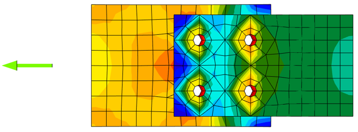
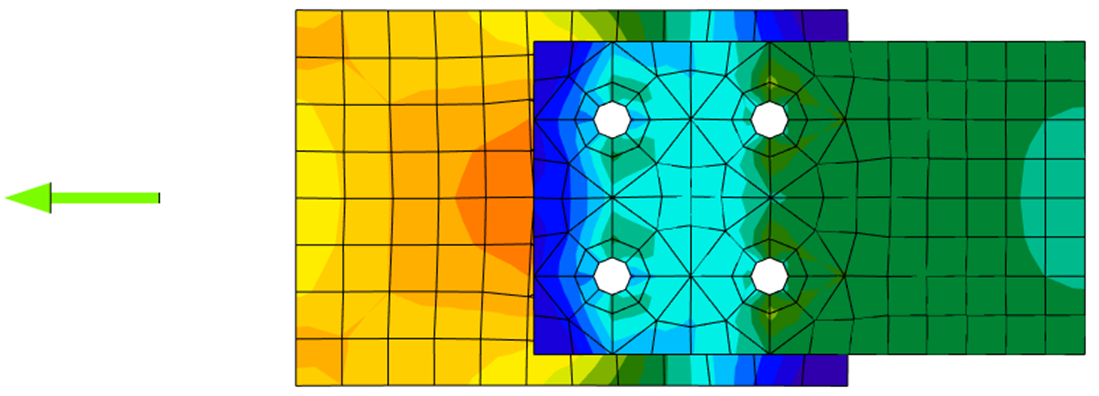
Distribution des contraintes dans un assemblage boulon standard en cisaillement
Distribution des contraintes dans un assemblage boulon résistant au glissement en cisaillement