Idea Statica
  • Steel
  • Concrete
  • BIM & workflows
  • Support & Learning
  • Pricing
  • Company
  • Steel overview
  • Connection design
  • Member design
  • Parametric design
  • Steel case studies
  • Concrete overview
  • Walls and D-regions
  • Anchoring design
  • Members & cross-sections
  • Concrete case studies
  • BIM overview
  • Supported integrations
  • Checkbot
  • Viewer
  • APIs
  • Support Center
  • E-learning & certification
  • Blog
  • Downloads & Licensing
  • Plans
  • Free community tool
  • Enterprise customers
  • Students & educators
  • How much will you save?
  • About us
  • Contact
  • Research & development
  • Authorized resellers
  • Meet our customers
  • Career
  • Steel
    Steel overviewConnection designMember designParametric designSteel case studies
  • Concrete
    Concrete overviewWalls and D-regionsAnchoring designMembers & cross-sectionsConcrete case studies
  • BIM & workflows
    BIM overviewSupported integrationsCheckbotViewerAPIs
  • Support & Learning
    Support CenterE-learning & certificationBlogDownloads & Licensing
  • Pricing
    PlansFree community toolEnterprise customersStudents & educatorsHow much will you save?
  • Company
    About usContactResearch & developmentAuthorized resellersMeet our customersCareer
14-Day Trial
14-Day Trial
  • Steel
  • Concrete
  • BIM & workflows
  • Support & Learning
  • Pricing
  • Company

Subscribe to our newsletter

Company

  • About us
  • Partners
  • Careers
  • Patent

Resources

  • Customer projects
  • Case studies
  • Connection Library
  • Verification books

Legal

  • EULA
  • Global privacy policy
  • California Privacy
  • TOS Viewer
  • Licensing

Help

  • Contact
  • Quote request
  • Resellers
  • Downloads
FacebookInstagramLinkedInYouTube

© IDEA StatiCa 2009-2026

Trusted and used worldwide by engineers, fabricators & consultants.

Support CenterKnowledge Base ArticlesAnchor bolts
Advanced analysis types for your steel structures
Concrete cone area of single anchor and group of anchors
Effective area in check of contact stress in concrete
EN anchoring code-check improvement
Limitations to checks of anchors
Anchorage formulas, tooltips
Calculation of anchors with stand-off
Import of anchoring from Connection to Detail
Automatic anchoring code-selection with hooked anchors
Anchor bolts
Structural model of a concrete block
Code-check of anchors (EN)
Code-check of concrete blocks (EN)
Russian Standard (SP) anchorage
Check of anchors according to STO
Code-check of concrete block according to Russian standards
Check of concrete block according to SP - new
IDEA StatiCa Connection theoretical background for the advanced structural design of steel connections. Description of anchor bolts and their stiffness including anchors with stand-off. Structural design of welded and bolted connections.
SteelConnection designKnowledge baseConnectionAISC (USA)

Anchor bolts

This article is also available in
ENCZDEESFRITPTNLHUROKRPLTHTRVIZH

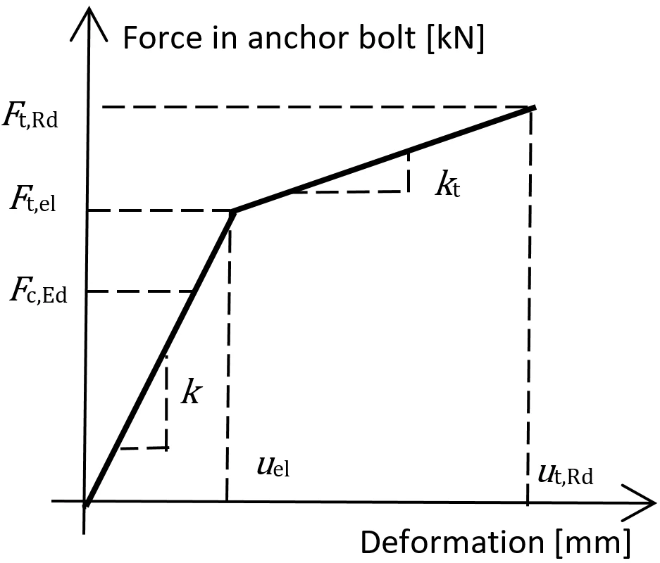
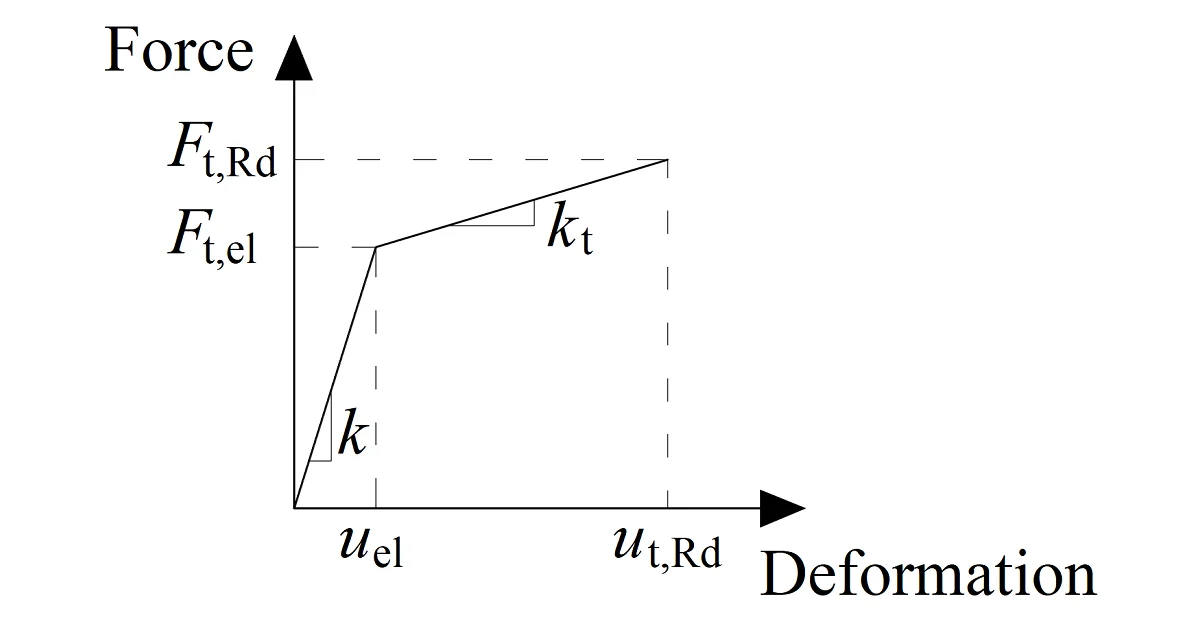
The anchor bolt is modeled with similar procedures as the structural bolts. The bolt is fixed on one side of the concrete block. Its length, Lb, used for bolt stiffness calculation, is taken as a sum of half of the nut thickness, washer thickness, tw, base plate thickness, tbp, grout or gap thickness, tg, and free the length embedded in concrete which is expected as 8d where d is a bolt diameter. Factor 8 is editable in the Code setup. This value is in accordance with the Component Method (EN1993-1-8); the free length embedded in concrete can be modified in Code setup. The stiffness in tension is calculated as k = E As / Lb. The load-deformation diagram of the anchor bolt is shown in the following figure. The values according to ISO 898:2009 are summarized in the table and in the formulas below.
IDEA StatiCa Connection theoretical background for the advanced structural design of steel connections. Description of anchor bolts and their stiffness including anchors with stand-off. Structural design of welded and bolted connections.

Load–deformation diagram of the anchor bolt

Ft,el=Ft,Rdc1c2−c1+1F_{t,el}=\frac{F_{t,Rd}}{c_1 c_2 - c_1 + 1}Ft,el​=c1​c2​−c1​+1Ft,Rd​​

kt=c1k;c1=Rm−Re(14A−ReE)Ek_t = c_1 k; \qquad c_1 = \frac{R_m - R_e}{\left ( \frac{1}{4} A - \frac{R_e}{E} \right )E}kt​=c1​k;c1​=(41​A−ERe​​)ERm​−Re​​

uel=Ft,elk;ut,Rd=c2uel;c2=AE4Reu_{el} = \frac{F_{t,el}}{k}; \qquad u_{t,Rd} = c_2 u_{el}; \qquad c_2 = \frac{AE}{4R_e}uel​=kFt,el​​;ut,Rd​=c2​uel​;c2​=4Re​AE​

where:

  • A – elongation
  • E – Young's modulus of elasticity
  • Ft,Rd – steel tensile resistance of the anchor
  • Rm – ultimate (tensile) strength
  • Re – yield strength

The stiffness of the anchor bolt in shear is taken as the stiffness of the structural bolt in shear.

Anchor bolts with stand-off

Anchors with stand-off can be checked as a construction stage before the column base is grouted or as a permanent state. Anchor with stand-off is designed as a bar element loaded by shear force, bending moment, and compressive or tensile force. The anchor is fixed on both sides; one side is 0.5×d below the concrete level, the other side is in the middle of the thickness of the plate. The buckling length is conservatively assumed as twice the length of the bar element. Plastic section modulus is used. The forces in anchor with stand-off are determined using finite element analysis. The bending moment is dependent on the stiffness ratio of anchors and base plate.
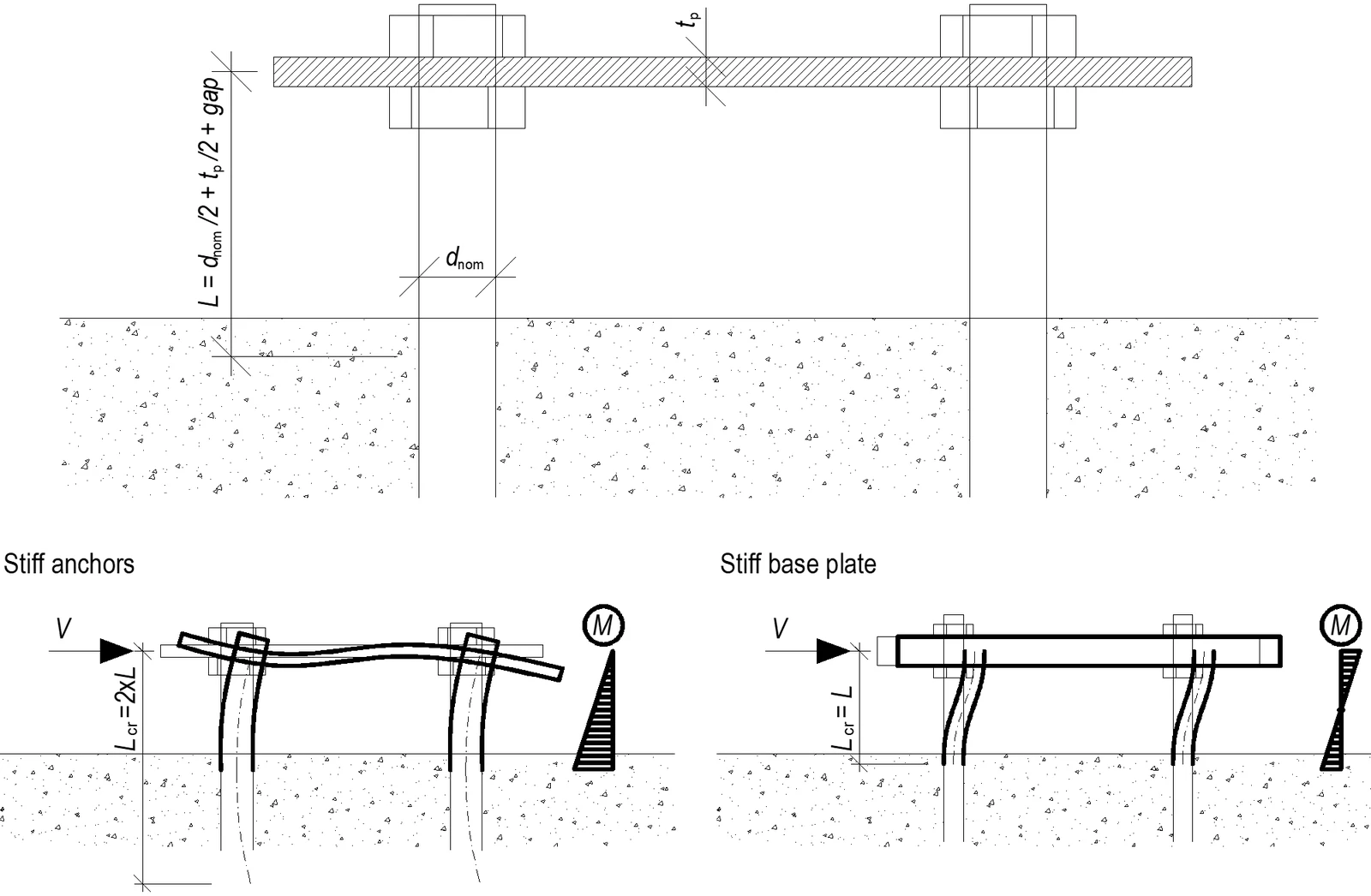
Anchors with stand-off – determination of lever arm and buckling lengths; stiff anchors are safe assumption
Related articles

IDEA StatiCa Connection theoretical background for the structural design of steel connections. Bolts and preloaded bolts, shear resistance, and behavior in tensile-shear interaction. Structural design of welded and bolted connections.
  • Steel
  • Connection
  • AISC (USA)
  • AS (Australia)
  • CSA (Canada)
  • EN (Eurocode)
  • IS (India)
  • GB (China)
  • HKG (Hong Kong)
  • SP 16 (Russia)
  • CBFEM
  • Bolts
  • +12
  • Steel
  • Connection
  • AISC (USA)
  • AS (Australia)
  • CSA (Canada)
  • EN (Eurocode)
  • IS (India)
  • GB (China)
  • HKG (Hong Kong)
  • SP 16 (Russia)
  • CBFEM
  • Bolts

Knowledge base

Bolts and preloaded bolts connections

Read more
Structural design of steel connections and concrete members. A concrete block is not modeled but only simulated by Winkler subsoil model with uniform stiffness.
  • Steel
  • Connection
  • AISC (USA)
  • AS (Australia)
  • CSA (Canada)
  • EN (Eurocode)
  • IS (India)
  • GB (China)
  • HKG (Hong Kong)
  • SP 16 (Russia)
  • Anchoring
  • CBFEM
  • Steel-to-concrete
  • +13
  • Steel
  • Connection
  • AISC (USA)
  • AS (Australia)
  • CSA (Canada)
  • EN (Eurocode)
  • IS (India)
  • GB (China)
  • HKG (Hong Kong)
  • SP 16 (Russia)
  • Anchoring
  • CBFEM
  • Steel-to-concrete

Knowledge base

Structural model of a concrete block

Read more
Structural design of footing with diagonal (EN)
  • Steel
  • EN (Eurocode)
  • Connection
  • Anchoring
  • Concrete block
  • Steel-to-concrete
  • +6
  • Steel
  • EN (Eurocode)
  • Connection
  • Anchoring
  • Concrete block
  • Steel-to-concrete

Tutorials

Structural design of footing with diagonal (EN)

Read more