
End Plate Moment (EPM) Prequalified Connection - AISC
This verification example was prepared in a joint project between Ohio State University and IDEA StatiCa. The authors are listed below:
- Baris Kasapoglu, Ph.D. student
- Ali Nassiri, Ph.D.
- Halil Sezen, Ph.D.

2.1. Introduction
Bolted unstiffened and stiffened extended end plate moment (EPM) connection is another prequalified connection permitted to be used in high seismic regions by AISC 358 (2016) Chapter 6. In this chapter, six tested EPM specimens were selected from the literature. Their flexural capacities were calculated using IDEA StatiCa and following the AISC design procedure, and the results were compared with observations made during the experiments. Also, one of the specimens was selected as a baseline model, and moment-rotation analysis was performed using the IDEA StatiCa and ABAQUS for this connection. The numerically obtained moment rotation curves were compared with each other. Moreover, the moment-plastic rotation relationship obtained through IDEA StatiCa analysis was compared with the experimentally measured one provided in the test report.
2.2 Experimental Study
Six EPM specimens were subjected to cycling loading, and their responses were investigated at Virginia Polytechnic Institute and State University as part of the SAC steel project (Sumner et al., 2000). The test identification (ID) of “4E-1.25-1.5-24” was selected as the baseline model and the other specimens with IDs of “4E-1.25-1.125-24”, “8ES-1.25-2.5-36”, “8ES-1.25-1-30”, “8ES-1.25-1.75-30”, and “8ES-1.25-1.25-36” were selected as variation connections and numbered respectively. The properties of the specimens are presented in Table 2.1, and the configurations of the six connections are shown in Figures 2.1 through 2.3.
Table 2.1: Properties of the EPM specimens
| Specimen No. | Beam | Column | Doubler plate thickness (in.) | Continuity plate thickness (in.) | Number of bolts (Grade) | End-plate thickness (in.) | End-plate stiffener thickness (in.) |
| Baseline | W24x68 | W14x120 | 1/2 | 5/8 | Four (A490) | 1 1/2 | - |
| Var-1 | W24x68 | W14x120 | 1/2 | 5/8 | Four (A325) | 1 1/8 | - |
| Var-2 | W36x150 | W14x257 | 3/4 | - | Eight (A490) | 2 1/2 | 3/4 |
| Var-3 | W30x99 | W14x193 | 3/8 | 5/8 | Eight (A325) | 1 | 1/2 |
| Var-4 | W30x99 | W14x193 | 3/8 | 5/8 | Eight (A490) | 1 3/4 | 1/2 |
| Var-5 | W36x150 | W14x257 | 3/4 | - | Eight (A325) | 1 1/4 | 3/4 |

Figure 2.1: Left) Configuration of baseline model; Right) configuration of Variation 1 (Sumner et al., 2000)
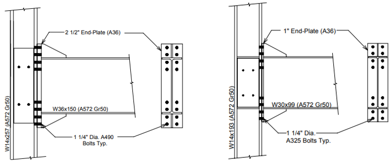
Figure 2.2: Left) Configuration of Variation 2; Right) configuration of Variation 3 (Sumner et al., 2000)

Figure 2.3: Left) Configuration of Variation 4; Right) configuration of Variation 5 (Sumner et al., 2000)
The baseline model and Variation 1 (Var-1) are four-bolt unstiffened extended EPM connections while the others are eight-bolt stiffened extended EPM connections. All bolts have a diameter of 1 1/4 in., and the bolt grades vary from ASTM A325 (fnt = 90 ksi) to A490 (fnt = 113 ksi) where fnt is nominal tensile strength. Each connection has one sided doubler plate plug welded to the column web and 5/16 in. double sided fillet weld between beam web and end plate. The measured material properties for the beam flange, column flange and end plate are presented in Table 2.2.
Table 2.2: Material properties of selected EPM specimens
| Specimen No. | Section | Yield stress (ksi) | Ultimate stress (ksi) |
| Baseline | W14x120 (column flange) | 52.0 | 70.6 |
| W24x68 (beam flange) | 53.6 | 70.7 | |
| 1 1/2 in. end plate | 38.1 | 68.8 | |
| Var-1 | W14x120 (column flange) | 52 | 70.6 |
| W24x68 (beam flange) | 53.6 | 70.7 | |
| 1 1/8 in. end plate | 37.9 | 63.4 | |
| Var-2 | W14x257 (column flange) | 51.2 | 68.3 |
| W36x150 (beam flange) | 54.5 | 70.4 | |
| 2 1/2 in. end plate | 38.2 | 72.3 | |
| Var-3 | W14x193 (column flange) | 55.5 | 74.3 |
| W30x99 (beam flange) | 54.9 | 70.8 | |
| 1 in. end plate | 37.8 | 60.8 | |
| Var-4 | W14x193 (column flange) | 55.5 | 74.3 |
| W30x99 (beam flange) | 54.9 | 70.8 | |
| 1 3/4 in. end plate | 37.2 | 63.4 | |
| Var-5 | W14x257 (column flange) | 51.2 | 68.3 |
| W36x150 (beam flange) | 54.5 | 70.4 | |
| 1 1/4 in. end plate | 40.5 | 67.1 |
The baseline model was designed to develop 110% of the nominal plastic moment capacity of the beam (, where is yield stress and is the plastic section modulus of beam). During testing, initial yielding occurred in the web and both flanges of the beam, and severe local buckling of the beam was observed during further cycles (Figure 2.4).
Variation 1 was designed with a thinner end plate and less strong bolts compared to the baseline model to develop 80% of the nominal plastic moment capacity of the beam. Initial yielding occurred in the beam web followed by yielding of the end plate (Figure 2.5). As the number of cycles increased, it was observed that the specimen failed due to the bolt ruptures and no local buckling of the beam was observed. The baseline and Variation 1 specimens were tested using the same test setup. The load was applied to the beam at a distance of 14 ft 1 3/4 in. from the column centerline. The photos after testing and moment-total plastic rotation relationships which include plastic rotations of the beam, column, and panel zone are illustrated in Figures 2.4 and 2.5 for the baseline model and Variation 1, respectively.
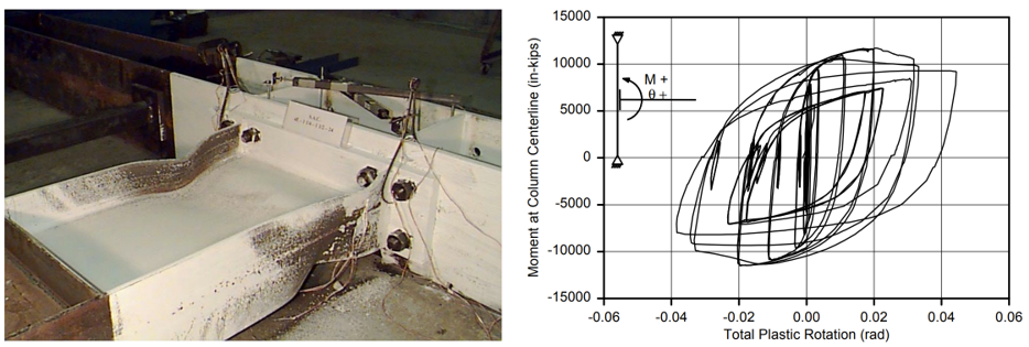
Figure 2.4: Left) Baseline model after testing; Right) moment-total plastic rotation relationship (Sumner et al., 2000)
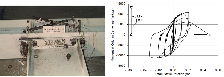
Figure 2.5: Left) Variation 1 after testing; Right) moment-total plastic rotation relationship (Sumner et al., 2000)
Variation 2 connection specimen was designed to develop 110% of the nominal plastic moment capacity of the beam. Initial yielding occurred in the end plate stiffener. Full yielding of the beam flanges and end plate stiffener was observed followed by local buckling of the beam flanges, beam web, and column web doubler plate (Figure 2.6).
Variation 3 was designed to develop 80% of the nominal plastic moment capacity of the beam. The initial yielding occurred in the beam flanges at the base of the stiffeners and in the end plate between the inner rows of the bolts. During the further cycles, severe yielding in the end plate and end plate stiffener was observed and local buckling in the beam flanges was reported (Figure 2.7). The moment-total plastic rotation relationships for Variation 2 and 3 specimens are shown in Figures 2.6 and 2.7, respectively.
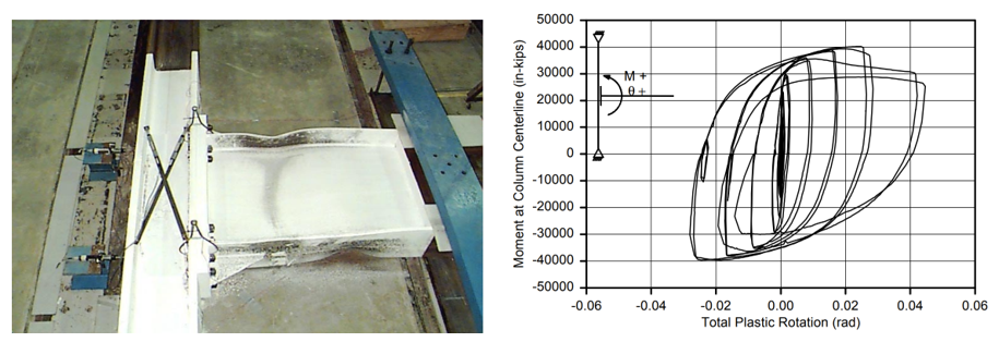
Figure 2.6: Left) Variation 2 after testing; Right) moment-total plastic rotation relationship (Sumner et al., 2000)
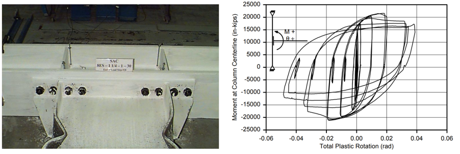
Figure 2.7: Left) Variation 3 after testing; Right) moment-total plastic rotation relationship (Sumner et al., 2000)
Variation 4 was designed to develop 110% of the nominal plastic moment capacity of the beam with a thicker end plate and the stronger bolts compared to Variation 3. The initial yielding occurred in the beam flanges and in the doubler plate. Severe local flange buckling in the beam flanges was observed and no yielding occurred in the end plate and end plate stiffener during the experiment (Figure 2.8). Note that these two specimens were evaluated in the same test setup, and the loading was applied to the tip of the beam at a distance of 20 ft and 1 1/4 in. from the column centerline.
Variation 5 was designed to develop 110% of the nominal plastic moment capacity of the beam with a thicker end plate and stronger bolts compared to Variation 2. The initial yielding was observed in the end plate stiffener. During the continued cycles, bolt rupture was observed (Figure 2.9). The loading was applied to the beam at a distance of 22 ft and 1 13/16 in. from the column centerline. The measured moment-total plastic rotation relationships are shown in Figures 2.8 and 2.9 for Variations 4 and 5, respectively.
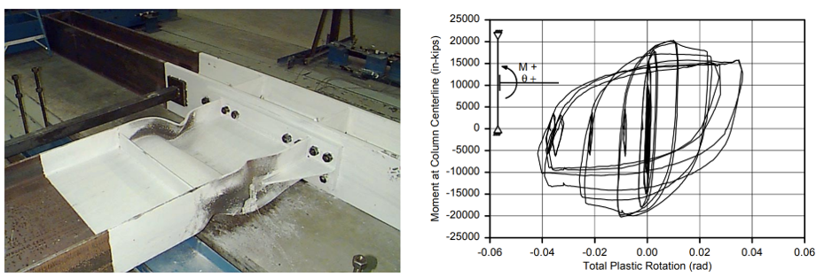
Figure 2.8: Left) Variation 4 after testing; Right) moment-total plastic rotation relationship (Sumner et al., 2000)
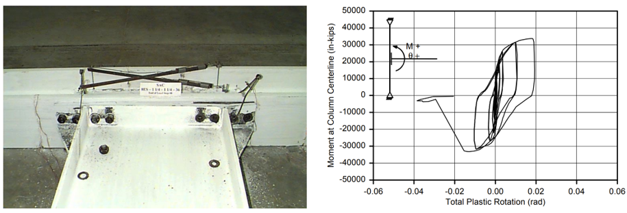
Figure 2.9: Left) Variation 5 after testing; Right) moment-total plastic rotation relationship (Sumner et al., 2000)
2.3 Code Design Calculations
The procedure outlined in Section 6.8 of AISC 358 (2016) for EPM connections were followed, and the following checks were performed for the six specimens.
- Check prequalification limits (AISC 358 (2016) Sec. 6.3)
- Check that probable maximum moment at the face of the column, \(M_{f}\), does not exceed available strength \(f_{d}M_{pe}\). (AISC 358 (2016) Eq. 6.8-1)
- Check the bolt diameters (AISC 358 (2016) Eq. 6.8-3)
- Check the end plate thickness (AISC 358 (2016) Eq. 6.8-5)
- Check shear yielding of the extended portion of the end plate for four-bolt extended unstiffened end plate (AISC 358 (2016) Eq. 6.8-7)
- Check shear rupture of the extended portion of the end plate for four-bolt extended unstiffened end plate (AISC 358 (2016), Eq. 6.8-7)
- Check end-plate stiffener thickness (AISC 358 (2016), Eq. 6.8-9)
- Check stiffener width-to-thickness ratio (AISC 358 (2016), Eq. 6.8-10)
- Check bolt shear rupture strength (AISC 358 (2016), Eq. 6.8-11)
- Check bolt-bearing/tear-out failure of the end plate and column (AISC 358 (2016), Eq. 6.8-12)
- Check the weld between beam web and end plate (AISC Design Guide 4 (2003), Sec. 4.2.13)
- Check the column flange for flexural yielding (AISC 358 (2016), Eq. 6.8-13)
- Check the local column web yielding strength of the unstiffened column web at the beam flanges (AISC 358 (2016), Eq. 6.8-16-17)
- Check the unstiffened column web buckling strength at the beam compression flange
(AISC 358 (2016), Eq. 6.8-18-20)
- Check the unstiffened column web crippling strength at the beam compression flange
(AISC 358 (2016), Eq. 6.8-21-24)
- Check the panel zone (AISC 358 (2016), Section 6.4(1))
It is assumed that the frame system satisfies the design requirements of special moment frames (SMF). The distance between the column centerlines, L, is assumed to be equal to 360 in. in the six specimens considered here (Table 2.1). The measured beam flange and column flange properties were used for the beam, column respectively while the measured end plate properties were used for end plate. It is also assumed that the material properties of rest of the plates (end plate stiffener, continuity plate, doubler plate) are identical with the measured properties of the end plate (See Table 2.2). The nominal tensile strength (\(f_{nv}\)) and shear strength (\(f_{ny}\)) given by AISC Table J3.2 were used for A325 and A490 bolts (threads are excluded) presented in Table 2.3.
Table 2.3: Nominal strength of bolts
| Bolt type | Nominal tensile strength (\(f_{nt}\)) | Nominal shear Strength (\(f_{nv}\)) |
| A325 | 90 ksi | 68 ksi |
| A490 | 113 ksi | 84 ksi |
The summary of the AISC 358 (2016) design checks of the six specimens is presented in Table 2.4. The details of the design calculations and checks are provided in Appendices C and D.
Table 2.4: AISC 358 (2016) design checks for the specimens
| AISC design checks | Baseline | Var-1 | Var-2 | Var-3 | Var-4 | Var-5 |
| Bolt diameter | OK | Not OK | Not OK | OK | OK | Not OK |
| End plate thickness | OK | Not OK | OK | Not OK | OK | Not OK |
| End plate stiffener thickness | - | - | Not OK | Not OK | Not OK | Not OK |
| Yielding of the extended portion of the end plate | OK | Not OK | - | - | - | - |
| Shear rupture of the extended portion of the end plate | OK | OK | - | - | - | - |
| Compression bolt shear rupture | OK | OK | OK | OK | OK | OK |
| Bolt-bearing/tear-out failure of the end plate and column flange | OK | OK | OK | OK | OK | OK |
| Weld - between beam web and end plate | OK | OK | Not OK | Not OK | Not OK | Not OK |
| Column flange thickness | OK | OK | OK | OK | OK | OK |
| Continuity plate requirement | Required | Required | Required | Required | Required | Required |
| Continuity plate thickness | OK | OK | - | OK | OK | - |
| Continuity plate weld | Not OK | Not OK | - | Not OK | OK | - |
| Column-beam relationships | OK | OK | Not OK | Not OK | Not OK | Not OK |
| Panel zone | OK | OK | OK | OK | OK | OK |
The design guidelines provided in AISC 358 (2016) Section 6.8 for extended stiffened and unstiffened end plate moment connections ensure that yielding does not occur on the connection side (e.g., in end plate or bolts). However, some of the checks performed for the test specimens were not satisfied. Therefore, further investigation may be necessary to investigate the failure modes and moment capacities of the EPM connections satisfying the requirements of AISC 358 (2016) standard.
According to Borgsmiller (1995) and AISC Steel Design Guide 4 (DG 4) (2003), controlling the damage limit state of an EPM connection can be predicted if the following limit states are known:
- Moment strength of beam
- Yield moment strength of end plate
- Yield moment strength of column flange
- Tensile rupture strength of bolts
If no prying moment tensile rupture strength is less than or equal to 90% of the yield moment strengths of the end plate and column flange, thick plate behavior is expected. In other words, if the applied moment is larger than this, the end plate behaves as a thin plate and prying action is required to be considered in the bolts (AISC DG 4, 2003). The moment strength of the beam at plastic hinge location, \(M_{by@ph}\), the yield moment strength of the end plate, \(M_{ply}\), the yield moment strength of the column flange, \(M_{cf}\), and no prying moment for the bolt strength (bolt tensile rupture limit), \(M_{bnp}\), are calculated as follows:
\(M_{by@ph} = F_{yb}Z_{bx}\) (2.1)
\(M_{ply} = Y_{p}F_{epy}{t_{p}}^2\) (2.2)
\(M_{cf} = Y_{c}F_{cy}{t_{cf}}^2\) (2.3)
\(M_{bnp} = 2F_{nt}(\pi\frac{{d_{bolt}}^2}{4})(h_{0} + h_{1})\) (2.4)
where \(F_{yb}\) is yield stress of beam, \(Z_{bx}\) is plastic section modulus of beam, \(Y_{p}\) is end plate yield line mechanism parameter, \(F_{epy}\) is yield stress of end plate, \(t_{p}\) is end plate thickness, \(Y_{c}\) is column flange yield line mechanism parameter, \(F_{cy}\) is yield stress of column, \(t_{cf}\) is column flange thickness, \(F_{nt}\) is nominal tensile stress of bolt, \(d_{bolt}\) is bolt diameter, \(h_{0}\) is distance from centerline of compression flange to the tension-side outer bolt row, and \(h_{i}\) is distance from centerline of compression flange to the centerline of the \(i^{th}\) tension bolt row. Plastic moment capacity of the beam at column face can be calculated by considering the additional moment resulting from the shear force at the plastic hinge location as follows:
\(M_{by@foc} = (M_{by@ph} + VS_{h})\) (2.5)
where \(M_{by@foc}\) is flexural moment capacity of beam at column face, \(S_{h}\) is the distance between the column face and plastic hinge, and \(V\) is shear force on the beam at plastic hinge location. In Section 6.8 of AISC 358 (2016), is defined as the lesser of \(d_{b}/2\) or \(3b_{bf}\) for an unstiffened EPM connection and \(L_{st} + t_{p}\) for a stiffened EPM connection where \(d_{b}\) is depth of beam, \(b_{bf}\) is width of beam, \(L_{st}\) is length of stiffener, and \(t_{p}\) is end plate thickness. For the cantilever beam used in the six specimens, \(V\) is constant and equal to the applied load. Using Equations 2.1 through 2.5, the strengths of the test specimens were calculated and the controlling or the smallest moment capacity, \(M_{n}\) was determined and presented in Table 2.5.
Table 2.5: Summary of capacity calculations
| Specimen No. | \(S_{h}\) (in.) | \(V\) (kips) | \(M_{by@ph}\) (Kips-in.) | \(M_{by@foc}\) (kips-in.) | \(M_{ply}\) (kips-in.) | \(M_{cf}\) (kips-in.) | \(M_{bnp}\) (kips-in.) | \(M_{n}\) (kips-in.) |
| Baseline | 11.85 | 61.35 | 9,487 | 10,214 | 15,492 | 15,872 | 12,821 | 10,214 |
| Var-1 | 11.85 | 54.50 | 9,487 | 10,133 | 8,669 | 15,872 | 10,210 | 8,669 |
| Var-2 | 19 | 135.20 | 31,665 | 34,234 | 135,864 | 72,890 | 38,780 | 34,234 |
| Var-3 | 14 | 73.80 | 17,129 | 18,162 | 17,327 | 68,814 | 25,650 | 17,327 |
| Var-4 | 14.75 | 82.55 | 17,129 | 18,347 | 52,214 | 68,814 | 32,210 | 18,347 |
| Var-5 | 17.75 | 101.60 | 31,665 | 33,468 | 35,997 | 72,890 | 30,890 | 30,890 |
2.4 IDEA StatiCa Analysis
The six tested specimens were modeled in IDEA StatiCa. The aim was to simulate the behavior of the experiment. Their moment capacities and failure modes were identified using stress, strain analysis type. The measured material properties reported in Sumner et al. (2000) were used and resistance factors were set to 1.0. For the baseline model, the moment-rotation relationship was obtained using the connection stiffness analysis type (i.e., ST) in IDEA StatiCa.
2.4.1 Analysis of Baseline Model
IDEA StatiCa model was developed for the baseline model. The measured material properties were introduced, and the overstrength coefficients, \(R_{y}\), and \(R_{t}\), were set equal to 1.0 (see Figure 2.10). Also, all LRFD resistance factors were set to 1.0. To obtain the loads at the column centerline, a beam-column frame model was developed in SAP2000 using the lengths of column and beam in the test setup. The columns were fixed at both ends and a shear force of 59.00 kips was applied at a distance of 14 ft 1 3/4 in. from the centerline of the column. Shear and moment diagrams were obtained as shown in Figure 2.11. In this way, the loads at the nodes were calculated from the SAP2000 model, and the calculated loads were applied to the IDEA StatiCa model using the “loads in equilibrium” option at the beam position equal to zero which indicates the column centerline.
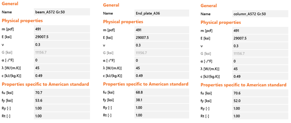
Figure 2.10: Material properties in IDEA StatiCa
For the capacity calculation, the stress/strain design analysis (i.e., EPS) with “loads in equilibrium” option was selected in IDEA StatiCa. The loads were gradually increased until any of the following is achieved:
- 5% of plastic strain in plates (beam, column, end plate and stiffener)
- 100% strength capacity in bolts
- 100% strength capacity in welds
When shear force and the corresponding moment values were increased to 61.35 kips and 10,414 kips-in., respectively, (with all loads proportionally being in equilibrium) 5% of the plastic strain limit was reached in the beam flange (Figure 2.12). Using “ST” analysis, the moment-rotation relationship was obtained and is shown in Figure 2.13.
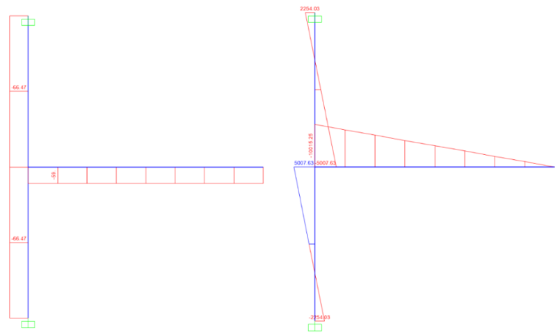
Figure 2.11: Shear force and moment diagram (SAP2000)

Figure 2.12: IDEA StatiCa model for Baseline Model under the moment of 10,414 kips-in.

Figure 2.13: Moment-rotation relationship for Baseline Model
2.4.2 Analysis of Variation 1
Following the same procedure described for the baseline model, IDEA StatiCa model was developed for the specimen Variation 1 (Figure 2.1). During the incremental loading, it was observed that the inner bolts reached their tensile rupture capacities when the shear force and the corresponding moment were 54.20 kips and 9,200 kips-in., respectively (Figure 2.14). Also, the deformed shape of the model shows that the prying action occurred in the end plate when the capacity was achieved.
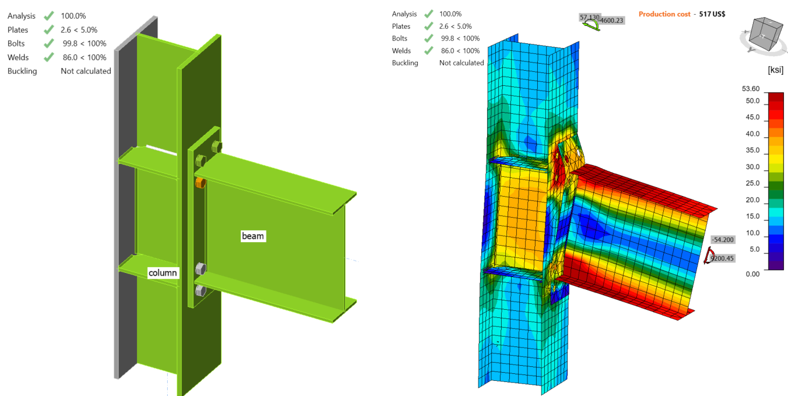
Figure 2.14: IDEA StatiCa model for Variation 1 under the moment of 9,200 kips-in.
2.4.3 Analysis of Variation 2
Following the same procedure described for the baseline model, IDEA StatiCa analysis was performed for the specimen Variation 2. It was observed that the fillet weld between beam web and end plate reached its strength capacity when the shear force and the corresponding moment were 135.20 kips and 35,938 kips-in., respectively (Figure 2.15).
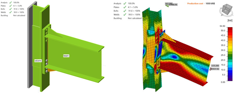
Figure 2.15: IDEA StatiCa model for Variation 2 under the moment of 35,938 kips-in.
2.4.4 Analysis of Variation 3
Following the same procedure, the moment strength capacity of the specimen Variation 3 was calculated in IDEA StatiCa. The incremental loading was stopped when any of the failure limit was achieved. The fillet weld between beam web and end plate reached its strength capacity when the shear force and the corresponding moment were 73.80 kips and 17,804 kip-in., respectively (Figure 2.16).
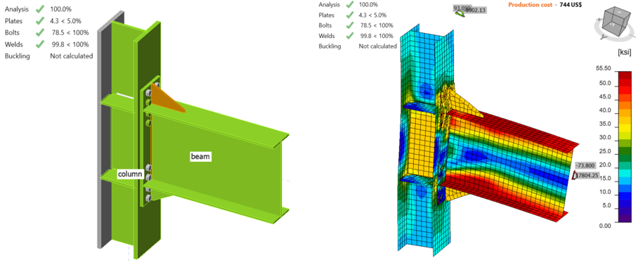
Figure 2.16: IDEA StatiCa model for Variation 3 under the moment of 17,804 kips-in.
2.4.5 Analysis of Variation 4
IDEA StatiCa analysis was performed for Variation 4 following the same steps. It was observed that 5% of the plastic strain limit was reached in the beam flange when shear force of 82.55 kips and the corresponding moment of 19,915 kips-in. were reached (Figure 2.17).
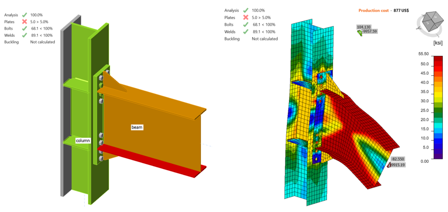
Figure 2.17: IDEA StatiCa model for Variation 4 under the moment of 19,915 kips-in.
2.4.6 Analysis of Variation 5
Following the same procedure, IDEA StatiCa model was developed for Variation 5, and its moment strength capacity was calculated. It was observed that 5% plastic strain occurred in the end plate stiffener when shear force of 101.60 kips and the corresponding moment of 27,007 kip-in. were reached (see Figure 2.18).
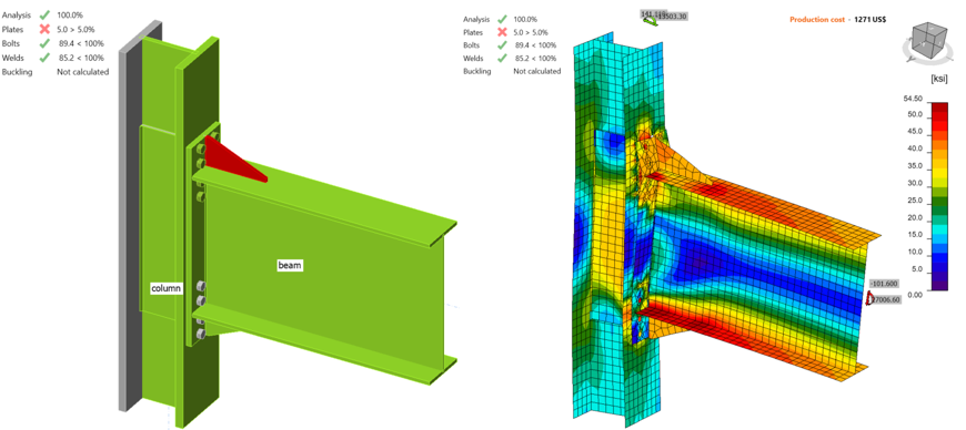
Figure 2.18: IDEA StatiCa model for Variation 5 under the moment of 27,007 kips-in.
The six specimens were analyzed using IDEA StatiCa and their moment capacities at the column centerline were calculated by representing their test conditions. To compare the moment capacities with the ones calculated following the AISC 358 procedure, the moment capacities at the column face were calculated using Eq. 2.6 and presented in Table 2.6.
\(M_{y@foc}\) = \(M_{y@cc} - V\frac{d_{c}}{2}\) (2.6)
where \(M_{y@foc}\) is moment capacity at the column face, \(M_{y@cc}\) is moment capacity at the column centerline, \(V\) is shear force, and \(d_{c}\) is depth of column.
Table 2.6: Moment capacity calculated by IDEA StatiCa
| Specimen No | \(M_{y@cc}\) (kips-in.) | \(M_{y@foc}\) (kips-in.) |
| Baseline | 10,414 | 9,969 |
| Var-1 | 9,200 | 8,808 |
| Var-2 | 37,453 | 34,829 |
| Var-3 | 19,951 | 17,232 |
| Var-4 | 19,915 | 19,275 |
| Var-5 | 29,372 | 26,173 |
2.5. ABAQUS Analysis
In this section, the baseline model developed in Section 2.4.1 was constructed again using ABAQUS software (version 2022) and results were compared with IDEA StatiCa. The CAD model for the finite element analysis was generated using the IDEA StatiCa’s viewer platform. The eight bolts and all 26 weld lines in four different lengths were then added to the assembly using the CAD interface in ABAQUS. The same vertical load of 59 kips and the corresponding moment of 100,15.25 kips-in. (around Y axis) were applied to a defined reference point (i.e., RF1) as shown in Figure 2.19. The analytical length of the column in IDEA StatiCa was 178.05 in. Therefore, to mimic the identical column length in ABAQUS, two other reference points (i.e., RF2 and RF3) were introduced 89.025 in. away from the center of the column along the Z axis in both directions (see Figure 2.19). These two reference points were fixed in all directions and were connected to the top and bottom faces of the column using a connector builder module in ABAQUS. In ABAQUS, the element size was chosen to be between 2.5-5 mm after mesh sensitivity analysis. The 3D stress, 8-node linear brick reduced integration (i.e., C3D8R ) element type was selected.
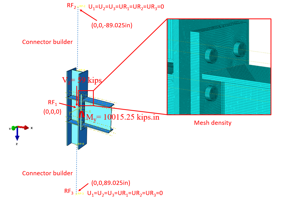
Figure 2.19: Model setup in ABAQUS
The tie constraint was applied between the weld lines and the attaching parts. The material behavior was modeled using bi-linear plasticity in ABAQUS. Other parameters, including density, elastic modulus, and Poisson’s ratio were taken from the IDEA StatiCa materials library. The numerical simulation was carried out on four processors (Intel Xenon (R) CPU E5-2698 v4 @ 2.20GHz) and took approximately 75 minutes to finish. Figure 2.20 compares the calculated von-Mises stress and plastic strain between the IDEA StatiCa and ABAQUS.
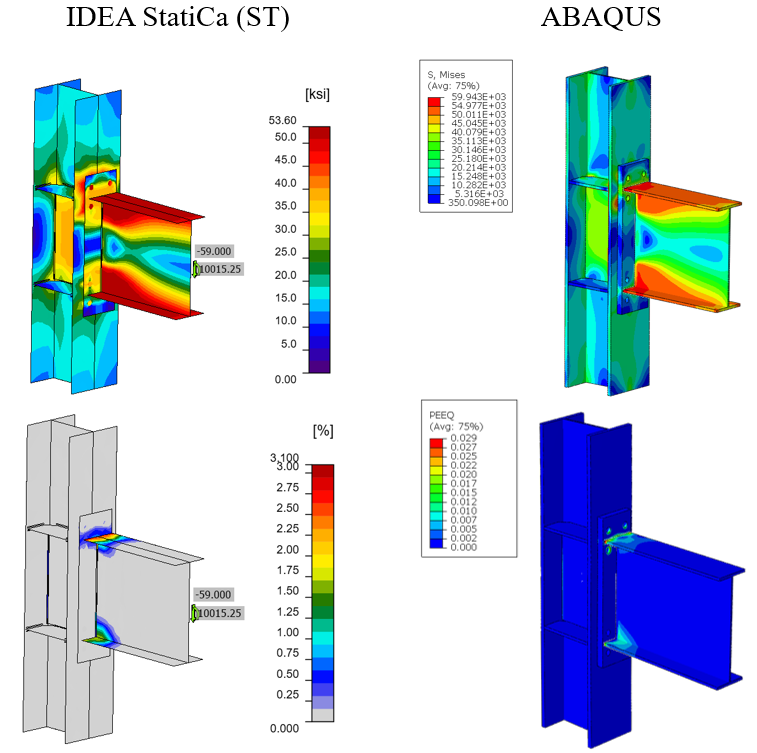
Figure 2.20: Comparison of the predicted von Mises stress (top row) and plastic strain (bottom row) between IDEA StatiCa and ABAQUS models
The maximum predicted stress in IDEA StatiCa was 54.40 ksi (on the beam top flange) while the ABAQUS model shows a maximum stress of 59.94 ksi at the same location. The slightly different stress distribution is likely due to the utilization of finer mesh in the ABAQUS model, the way that shear and tensile forces are being transferred between the bolt and plates as well as the simplified CAD model in IDEA StatiCa. Also, the maximum calculated plastic strain in IDEA StatiCa and ABAQUS were 3.1% and 2.9%, respectively (both at the beam top flange). Figure 2.21 depicts the comparison of the moment-rotation curve between the two software with respect to the column centerline.
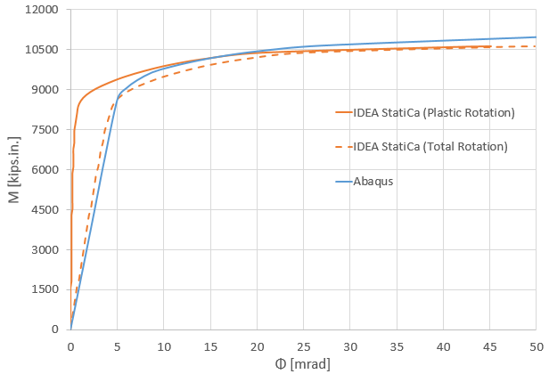
Figure 2.21: Moment-rotation comparison between IDEA StatiCa and ABAQUS
Note that in Figure 2.21, to obtain the total rotation by IDEA StatiCa (shown by dashed orange line), the linear column rotation at the column centerline was calculated using SAP2000 and then added to the default plastic rotation curve reported by IDEA StatiCa (shown by solid orange line). Both models offer comparable initial stiffness estimations. The minor discrepancy could be associated with the difference in the element types (i.e., solid element in ABAQUS versus shell element in IDEA StatiCa), the difference in load transferring between the bolts and plates, and the employment of the tie constraint in ABAQUS to represent the welds.
2.6 Summary and Comparison of Results
The six tested EPM connections were investigated using IDEA StatiCa and following the AISC design procedure. Also, the results from IDEA StatiCa baseline model were compared with those from the equivalent ABAQUS model. The calculated flexural moment capacities using IDEA StatiCa and AISC procedure are presented in Figure 2.22.
The connection of the baseline model was designed to develop 110% of the plastic moment capacity of the beam. As expected, it was reported that severe flange buckling occurred in the beam (Figure 2.4). Similarly, IDEA StatiCa and code-based design calculations identified the same failure mode. The moment capacity corresponding to 5% of the plastic strain limit computed by IDEA StatiCa is slightly less than the moment strength of the beam calculated following the AISC procedure (9,969 kips-in. versus 10,216 kips-in. in Figure 2.22). Also, the moment-rotation comparison was performed for the baseline model. The moment-plastic rotation curve was extracted from the test report and compared with the one provided by IDEA StatiCa as shown in Figure 2.23.
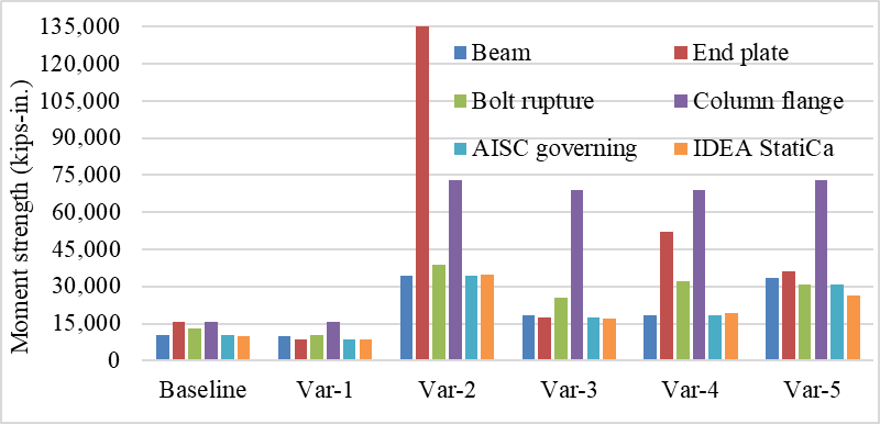
Figure 2.22: Moment capacity calculated by IDEA StatiCa and AISC procedure.

Figure 2.23: Moment-rotation comparison
During the test of Variation 1, it was observed that the specimen failed due to the bolt rupture. Similarly, IDEA StatiCa analysis for the same connection indicated that the inner bolts reached their tensile capacities (8,808 kips-in.). On the other hand, according to AISC design calculations, the minimum end plate thickness requirement was not satisfied and the controlling limit state was the end plate yield strength with moment strength of 8,669 kips-in. (note that bolt rupture strength was calculated by excluding effects of prying). Since the moment strength of end plate (8,669 kips-in.) is less than 110% of the no prying bolts tension rupture strength (10,210 kips-in.), prying action is expected to occur in the bolts and thus decreasing the bolt rupture capacity calculated with the assumption that no prying occurs in the bolts. In this example, IDEA StatiCa shows its capability in calculating bolt rupture capacity including the effects of prying on strength capacity of bolts while AISC 358 doesn’t permit prying action in bolts with the minimum thickness requirement of end plate.
It was stated in the test report of Variation 2 that initial yielding occurred in the end plate stiffener and severe local buckling was observed in the beam (Figure 2.6). IDEA StatiCa analysis showed that the specimen failed due to the fillet weld between the beam web and end plate (reached its strength capacity at 34,829 kips-in.). Similarly, AISC design checks confirmed that the fillet weld does not have enough strength (0.313 in. double sided weld was used while 0.46 in. was required). Following AISC design procedure, the moment strength was calculated as 34,323 kips-in. controlled by beam failure.
Regarding Variation 3, it was reported that the initial yielding occurred in the end plate stiffener followed by the end plate and beam yielding (Figure 2.7). According to the code-based calculations, the moment strength capacity of the specimen was 17,327 kips-in. controlled by end plate yield. Also, the specimen didn’t satisfy the required minimum size of the weld between the beam web and end plate (0.313 in. double sided weld was used while 0.38 in. was required). On the other hand, IDEA StatiCa analysis showed that the specimen failed due to the inadequate weld strength between the beam web and end plate (17,232 kips-in.).
For Variation 4, it was reported that severe local buckling occurred in the beam at the end of the experiment (Figure 2.8). Similarly, the moment strength of the beam is the governing limit state based on AISC design calculations. Likewise, the first member exceeding the 5% of plastic strain limit was the beam flange in IDEA StatiCa. The reason IDEA StatiCa calculated a slightly larger moment capacity than the one calculated following the AISC procedure (19,275 kips-in. versus 18,346 kips-in. in Figure 2.22) can be attributed to the contribution of the end plate stiffener.
In the test report of Variation 5, it was stated that the initial yielding occurred in the end plate stiffener and the specimen failed due to the bolt rupture which is the controlling limit state according to AISC design calculations. On the other hand, the IDEA StatiCa model failed due to end plate stiffener which didn’t satisfy the minimum thickness requirement of end plate stiffener. The reason IDEA StatiCa computed a less moment capacity than the one calculated following the AISC procedure (26,173 kips-in. versus 30,890 kips-in. in Figure 2.22) can be associated with the insufficient thicknesses of end plate (1.25 in. while 1.40 in. is required) and end plate stiffener (0.75 in. while 0.84 in. is required) based on AISC design checks. It should be noted that Variation 5 is the only specimen among the covered six EPM connections that didn’t satisfy both requirements.
Read the full study on prequalified connections!
References
AISC (2016), “Prequalified Connections for Special and Intermediate Steel Moment Frames for Seismic Applications, including Supplement No. 1,” American Institute of Steel Construction ANSI/AISC 358-16, Chicago, Illinois.
Sumner, E. A., Mays, T. W. and Murray, T. M. (2000), Cyclic Testing of Bolted Moment End-Plate Connections, Research No. CE/VPI-ST-00/03, Virginia Polytechnic Institute and State University, Blacksburg, VA.
Borgsmiller, J. T. (1995), Simplified Method for Design of Moment End-Plate Connections, Department of Civil Engineering, Virginia Polytechnic Institute and State University, Blacksburg, VA.
AISC Steel Design Guide 4 (2003), “Extended End-plate Moment Connections Seismic and Wind Applications,” American Institute of Steel Construction, Chicago, Illinois.