This verification example was prepared by Mark D. Denavit and Kayla Truman-Jarrell in a joint project of The University of Tennessee and IDEA StatiCa.
1. Description
A comparison between results from the component-based finite element method (CBFEM) and traditional calculation methods used in US practice for bracket plate connections are presented in this section. Both bolted and welded bracket plates are considered. The focus of this investigation is the strength of the eccentrically loaded bolt and weld groups that connect the bracket plates to the column flanges.
The instantaneous center of rotation method is the primary method described in the AISC Manual (2017) for computing the strength of eccentrically loaded bolt and weld groups. Details of the method differ between bolt and weld groups; however, the general approach is the same. The force in each individual bolt or segment of weld is assumed to act perpendicular to a line that passes through the individual component and the common center of rotation. The magnitude of the force in each component is based on equations representing the load deformation relationship. For welds, the load deformation relationship considers the direction of force with respect to the longitudinal axis of the weld. The center of rotation is typically found using an iterative process and is known to be valid when static equilibrium is achieved (i.e., the sum of the forces and moments equals zero). In practice, calculations using the instantaneous center of rotation method are completed using tabulated solutions for common bolt and weld groups provided in Parts 7 and 8 of the AISC Manual.
2. Bolted Bracket Plate Connections
A schematic of the bolted bracket plate connection investigated is presented in Fig. 1. The parameters change depending on the limit state being investigated. However, the typical connection has the following characteristics unless noted otherwise: bracket plate thickness of 5/8 in., ASTM A572 Grade 50 conforming steel for the plates (Fy = 50 ksi and Fu = 65 ksi), horizontal and vertical edge distances of leh = lev = 2.25 in., gage of g = 5.5 in., and 6 bolts in each vertical row with a spacing of s = 3 in. The bolts are 7/8 in. diameter A325 with threads not excluded from the shear plane and in standard holes. The column is a W12×106 conforming to ASTM A992 steel (Fy = 50 ksi and Fu = 65 ksi). The properties of the bolt group match those of Example II.A-24 of the AISC Design Examples (2017). The traditional calculations are performed following the provisions for load and resistance factor design (LRFD) in the AISC Specification (2016). The limit states evaluated are shear rupture of the bolt, bearing, tearout, and slip.
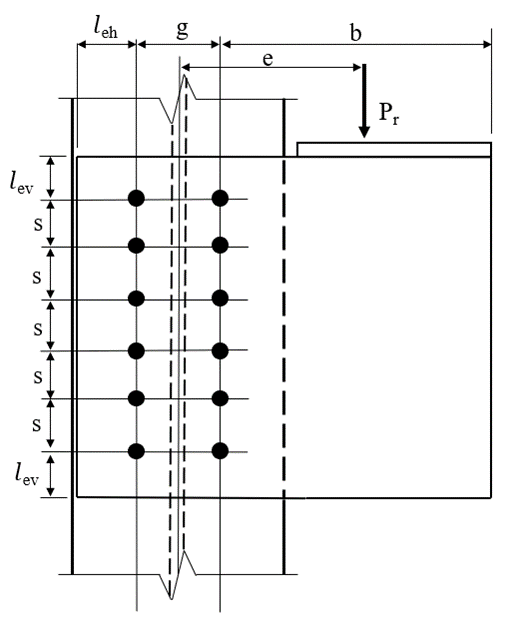
Fig. 1 Schematic of a bolted bracket plate connection
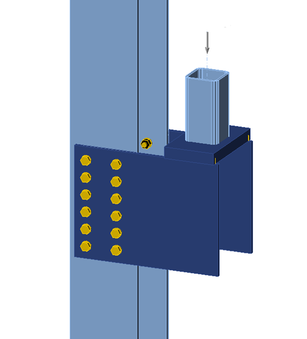
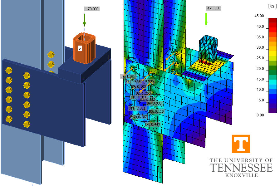
Fig. 2 IDEA StatiCa model of bolted bracket plate connection
3. Bolt Shear Rupture
The first investigation explores how the bolt utilization percentage varies with applied load. For one value of eccentricity, e = 16 in., the applied load was varied from 0 to 200 kips and the bolt utilization percentage as reported by IDEA StatiCa was recorded. The results are presented in Fig. 3. The relationship between applied load and bolt utilization percentage is essentially linear until an applied load of roughly 135 kips at which point the bolt utilization percentage plateaus at near 100% until an applied load of roughly 185 kips at which point the bolt utilization percentage again increases linearly. The load at which failure of the bolts indicated by IDEA StatiCa (i.e., with a red “x”) occurs later in the plateau, at an applied load of 174.7 kips. The strength of this connection per the traditional calculations is 172.6 kips.
These strength results for the same connection and a range of values of eccentricity are presented in Fig. 4. As expected, the maximum permitted applied load decreases with increasing eccentricity. The results from IDEA StatiCa are in close agreement with the traditional calculations.
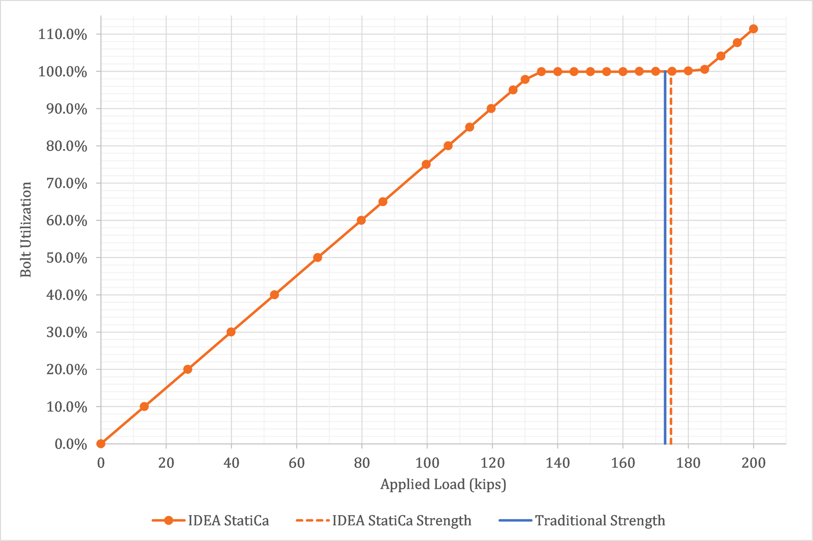
Fig. 3.a Bolt utilization percentage as a function of applied load
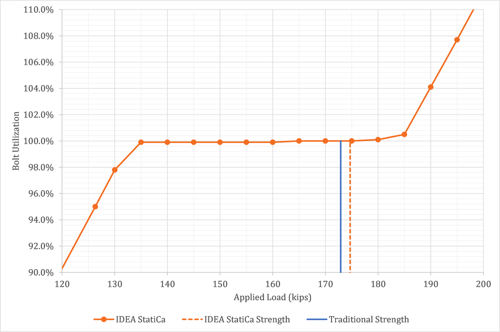
Fig. 3.b Bolt utilization percentage as a function of applied load (detail view)
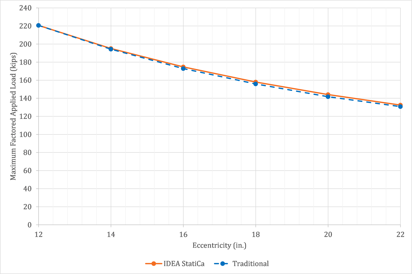
Fig. 4 Maximum factored applied load vs. eccentricity
4. Additional Bolt Groups
Additional bolt groups are investigated in this section. The connections investigated are like those investigated in the previous section but the first has a larger gage (g = 8 in.) and the second has only two bolts in each vertical row (g = 5.5 in., s = 6 in.). A larger column size (W14×132) was used with the connection with the larger gage to ensure minimum edge distance requirements were satisfied. The results for the larger gage are presented in Fig. 5 and the results for the connection with two bolts in each vertical row are presented in Fig. 6. As before, the IDEA StatiCa results are in close agreement with the traditional calculations.
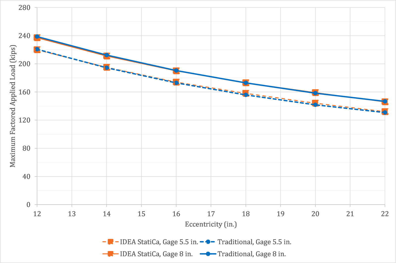
Fig. 5 Maximum factored applied load vs. eccentricity for bolted bracket plate connections with two different values of bolt gage
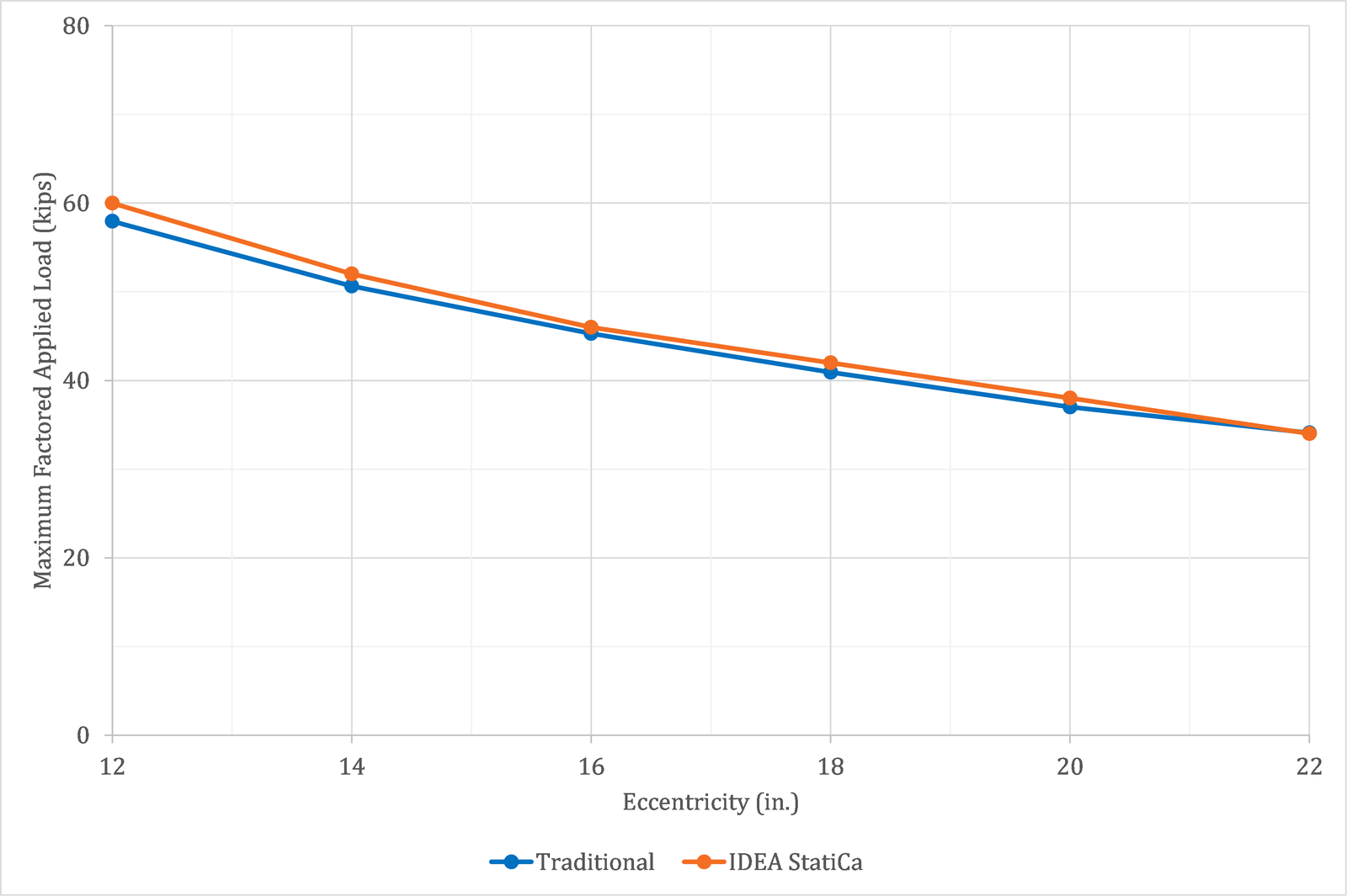
Fig. 6 Maximum factored applied load vs. eccentricity for bolted bracket plate connection with two bolts in each vertical row
5 Tearout
A disadvantage of the instantaneous center of rotation method is that the tabulated solutions assume that the bolts all have the same strength. The bolts in an eccentrically loaded bolt group may not all have the same strength if the edge distances are small and tearout controls over bearing or bolt shear rupture. This is additionally challenging for the traditional calculations since, when using the tabulated solutions, the direction of force for each bolt is not known and thus the clear distance, a key factor in tearout strength, cannot be accurately determined. When evaluating eccentrically loaded bolt groups with small edge distances, engineers often employ the “poison bolt method” whereby the strength of all the bolts is set equal to the lowest possible strength (i.e., that computed from the lowest possible clear distance). In IDEA StatiCa, tearout strength is computed individually for each bolt based on the computed direction of force.
A comparison between IDEA StatiCa results and results from traditional calculations using the poison bolt method are shown in Fig. 7. The connection for this comparison is like that described in Section 2 but with a bracket plate thickness of 3/8 in. and varying horizontal edge distance, leh. The edge distance varies between 1.125 in., the minimum edge distance per Table J3.4 of the AISC Specification (2016), and 2.25 in., a value at which bolt shear rupture will control over tearout. The results show close agreement, indicating that IDEA StatiCa is appropriately considering the effects of tearout in eccentrically loaded bolt groups.
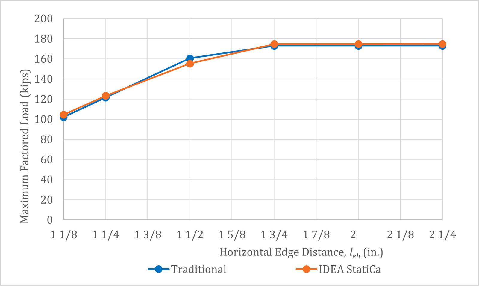
Fig. 7 Maximum factored applied load vs. horizontal edge distance
6 Slip Critical
The instantaneous center of rotation method is also applicable to slip critical connections even though the mechanics of force transfer are different than those assumed in the method. The results of a comparison using the same connection parameters as for the connection explored in Section 3 but for a slip critical connection are presented in Fig. 8. The average difference between the IDEA StatiCa results and traditional US methods is about 1.5%.
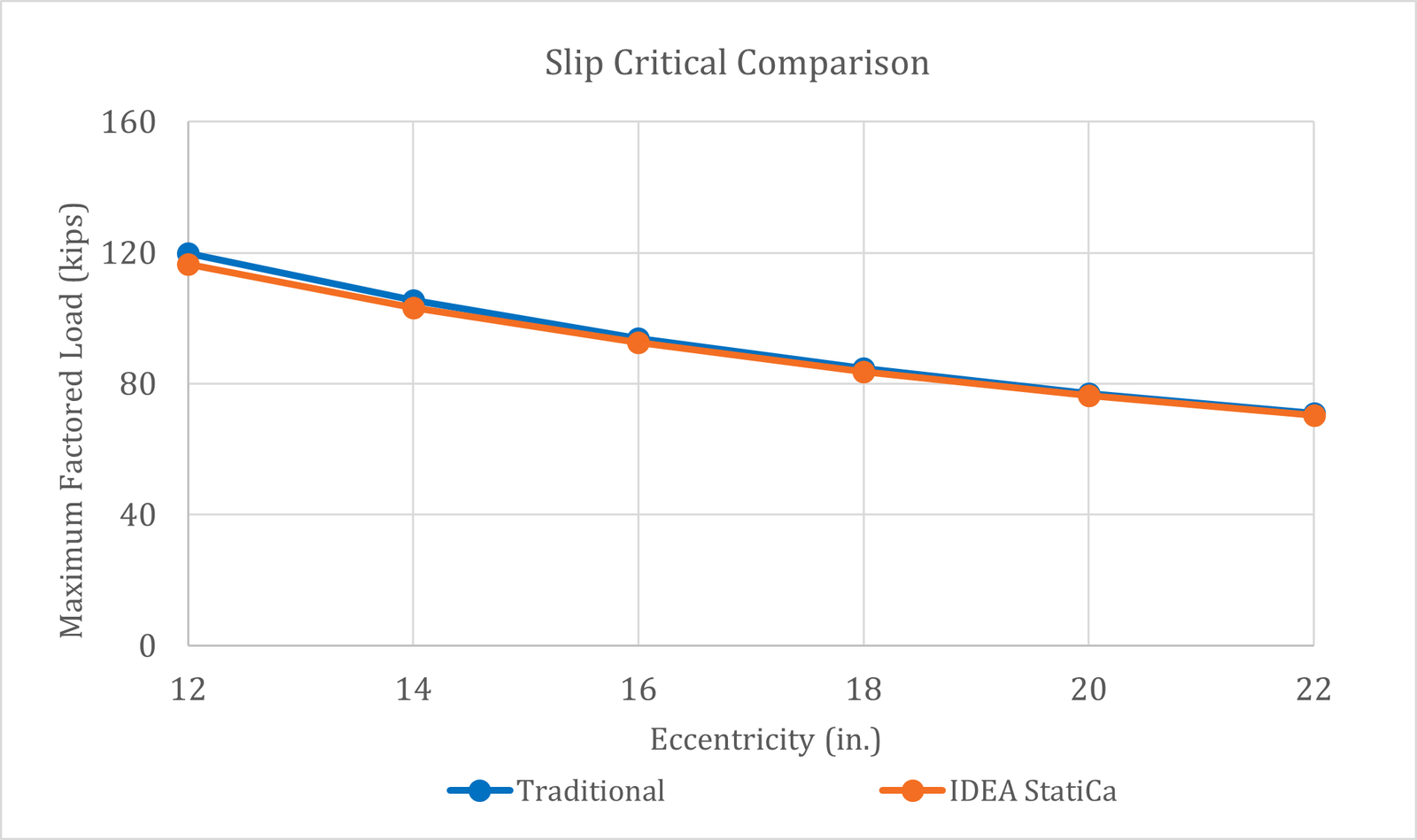
Fig. 8 Maximum factored applied load vs. eccentricity for slip-critical bolted bracket plate connection
7 Welded Bracket Plate Connections
A schematic of the welded bracket plate connection investigated is presented in Fig. 9 and an image of the IDEA StatiCa model is presented in Fig. 10. The parameters of the connections investigated are as follows: plate thickness of 9/16 in., ASTM A572 conforming steel for the plates (Fy = 50 ksi and Fu = 65 ksi), 3/8 in. fillet welds with E70XX weld metal, weld length, l = 10 in., and an aspect ratio of either k = 0.5 or k = 0.3. The column is a W8×40 conforming to ASTM A992 steel (Fy = 50 ksi and Fu = 65 ksi). The properties of the weld group match those of Example II.A-26 of the AISC Design Examples (2017). The traditional calculations are performed following the provisions for load and resistance factor design (LRFD) in the AISC Specification (2016). Only the limit state of weld rupture is evaluated.
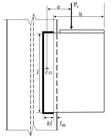
Fig. 9 Schematic of a welded bracket plate connection
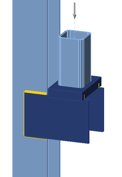
Fig. 10 IDEA StatiCa model of welded bracket plate connection
The strength of the connections per IDEA StatiCa and the traditional calculations for a range of eccentricities are presented in Fig. 11. As expected, and like the bolted connections, the maximum permitted applied load decreases with increasing eccentricity. The results show a relatively uniform level of conservatism for IDEA StatiCa as compared to traditional US practice. The case with k = 0.5 exhibits an average difference of approximately 17%, whereas the case with k = 0.3 exhibits an average difference of approximately 12%.
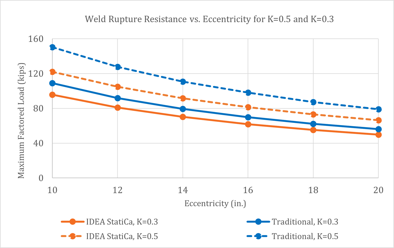
Fig. 11 Weld Rupture resistance with varying eccentricities for =0.3 and =0.5
6 Summary
This study compared the design of bracket plate connections by traditional calculation methods used in US practice and IDEA StatiCa. Key observations from the study include:
- The available strength of bolted bracket connections per IDEA StatiCa agrees very well with traditional calculations per the instantaneous center of rotation method.
- Eccentrically loaded bolt groups may exhibit a plateau during which IDEA StatiCa shows a bolt utilization of near 100% for a range of applied loads. The applied load at which IDEA StatiCa indicates failure (i.e., with a red “x”) was taken as the limit in this study and compares well to the traditional calculations.
- IDEA StatiCa detects the clear distance for each bolt individually for consideration of tearout, resulting in appropriate reductions in strength when edge distances are small.
- The available strength of welded bracket connections per IDEA StatiCa was found to be conservative in comparison to the traditional calculations using the instantaneous center of rotation method for the cases examined.