Block Shear Rupture in Bolted Connections (AISC)
Mark D. Denavit and Rick Mulholland prepared this verification example in a joint project of The University of Tennessee and IDEA StatiCa.
Description
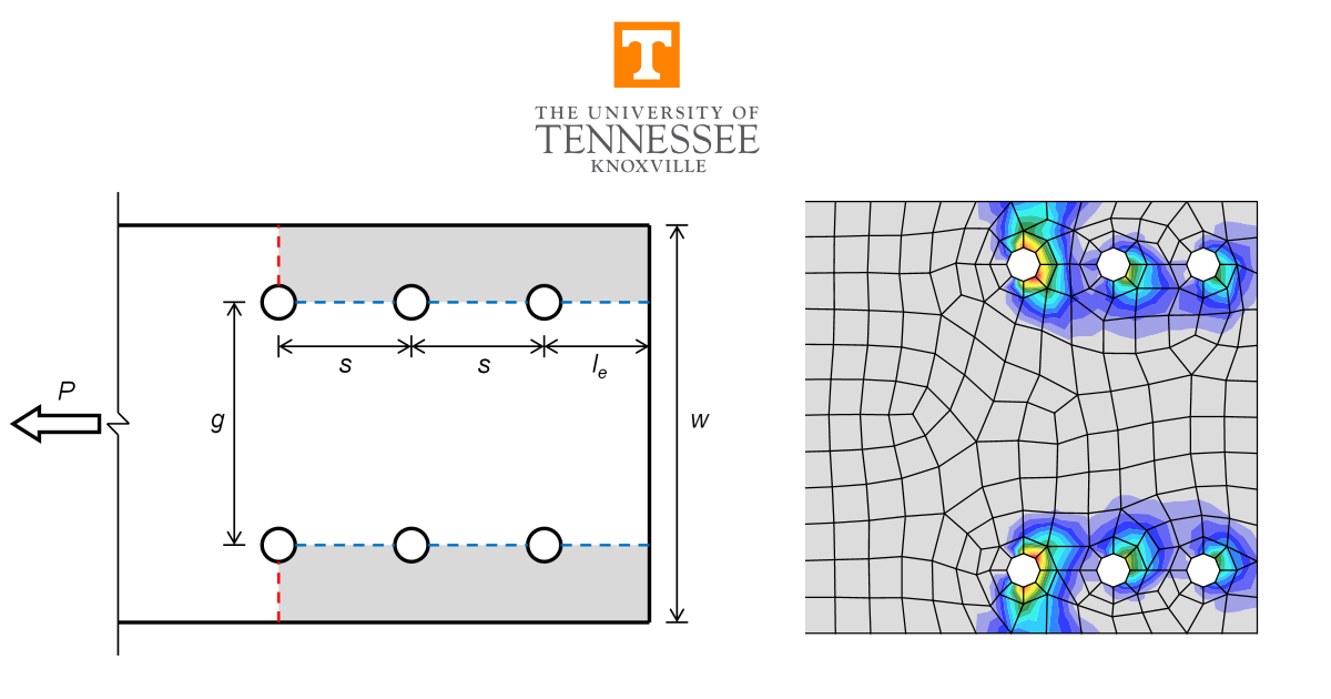
A comparison between results from the component-based finite element method (CBFEM) and traditional calculation methods used in US practice for the limit state of block shear rupture is presented in this study. Block shear rupture is a combined shear and tension failure and can occur in a variety of bolted and welded connections. This study focuses on bolted connections of plates in tension and coped beams as shown in the examples in Figure 1. Comparisons to experimental results are also presented.
Traditional calculations are performed in accordance with the provisions for load and resistance factor design (LRFD) in the AISC Specification (AISC 2022). The CBFEM results were obtained from IDEA StatiCa version 23.0. The maximum permitted loads were determined iteratively by adjusting the applied load input to a value that the program deems safe, but if increased by a small amount (0.1 kip) the program would deem unsafe by exceeding the 5% plastic strain limit or exceeding 100% bolt utilization. DR-type analyses can help identify maximum permitted loads. However, some approximation is made in the evaluation of the joint design resistance, therefore all results in this report are based on EPS type analysis.
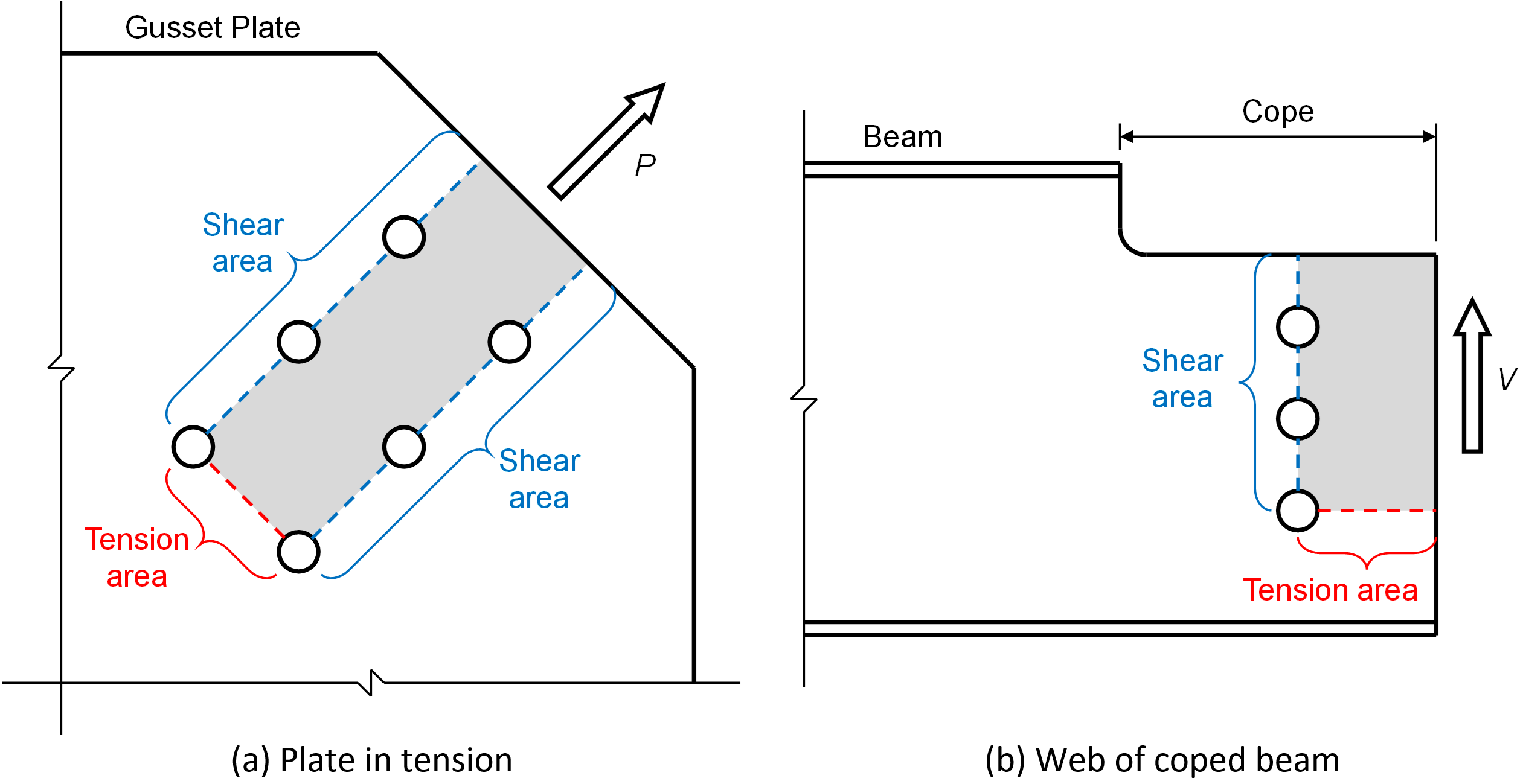
Figure 1 Examples of block shear rupture
Requirements for Block Shear Rupture in the AISC Specification
The design strength, \(\phi R_n\), for the limit state of block shear rupture defined in AISC Specification Section J4.3 as:
\[\phi R_n = \phi [ 0.6F_u A_{nv} + U_{bs} F_u A_{nt} \le 0.6 F_y A_{gv} + U_{bs} F_u A_{nt} ] \]
where:
- \( \phi = 0.75\)
- \(F_u\) – specified minimum tensile strength of steel
- \(F_y\) – specified yield strength of steel
- \(A_{nt}\) – net area subjected to tension
- \(A_{gv}\) – gross area subjected to shear
- \(A_{nv}\) – net area subjected to shear
- \(U_{bs}= 1.0\) – where the tension stress is uniform
- \(0.5\) – where the tension stress is non-uniform
An illustration of failure planes used to define Ant, Agv, and Anv is presented in Figure 2.

Figure 2 Net tension, net shear, and gross shear failure planes for block shear rupture
The tension stress is considered uniform and Ubs = 1.0 for the plates in tension evaluated in this work and webs of coped beams with a single vertical row of bolts. Webs of coped beams with multiple vertical rows of bolts are the most common case where the tension stress is considered non-uniform and Ubs = 0.5.
Other Strength Equations for Block Shear Rupture
Dhanuskar and Gupta (2019) evaluated experimental tests of 78 coped beams, 75 angles and tees, 14 flange-connected tees, and 182 gusset plate specimens, all of which failed in block shear rupture, in comparison to American, Indian, European, Canadian, Japanese, and Saudi Arabian design standards. Their results showed that the AISC Specification is moderately conservative for several cases. For this reason, comparisons are also made in this report to results from the block shear rupture strength equation in the Canadian design standard, CSA S16:19 Design of Steel Structures (CSA 2019) and a block shear rupture strength equation proposed by Teh and Deierlein (2017).
CSA S16
CSA S16 Section 13.11 covers block shear for tension members, beams, and plate connections. The factored resistance for a potential failure involving the simultaneous development of tensile and shear component areas is as follows:
When Fy < 460 MPa (66.7 ksi):
\[ T_r = \phi_u \left [ U_t A_{nt} F_u + 0.6 A_{gv} \frac{(F_y+F_u)}{2} \right ] \]
When Fy ≥ 460 MPa (66.7 ksi):
\[T_r = \phi_u [U_t A_{nt} F_u + 0.6 A_{gv} F_y ] \]
where:
- \(\phi_u =0.75\)
- \(U_t=1.0\) – for symmetrical blocks or failure patterns and concentric loading
- \(=0.9\) – for coped beams with one vertical row of bolts
- \(=0.3\) – for coped beams with two vertical rows of bolts
Teh and Deierlein (2017)
Teh and Deierlein (2017) investigated block shear rupture for plates in tension and proposed an alternative block shear rupture equation that assumes shear failure occurs on an “effective shear area”, taken as the mean between the gross and net shear areas. The researchers state, “The reasoning for this model is substantiated by Teh and Yazici (2013), who explain why there is only one feasible mechanism for the [U-shaped] block shear failure mode – namely, the tensile rupture and shear yielding mechanism. Teh and Uz (2015) have further pointed out that shear yielding in a block shear failure is typically accompanied by full strain hardening (0.6Fu), even though shear fracture very rarely, if ever, is the triggering failure mechanism. This can be explained by the large ductility of steel in shear, where the steel in the shear yielding zone can strain harden up to Fu and sustain large strains without the necking and rupture behavior that occurs in standard tensile coupons.”
Based on this reasoning, Teh and Deierlein (2017) propose the following equation for the nominal strength for the limit state of block shear rupture:
\[ R_n=F_uA_{nt}+0.6 F_u A_{ev} \]
where:
- \(A_{ev} = (A_{gv}+A_{nv} ) / 2\) – effective shear area,taken as the mean between the gross and net shear areas
An illustration of the effective shear planes for block shear rupture is presented in Figure 3.
Teh and Deierlein (2017) recommend that when the nominal strength is calculated using their proposed equation, a resistance factor, \(\phi=0.85\), should be used to determine the design strength. However, for the comparisons in this study, the resistance factor defined in the AISC Specification, \(\phi=0.75\), is used.
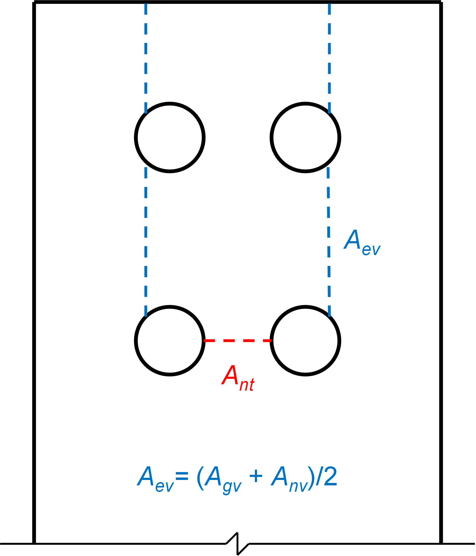
Figure 3 Net tensile and effective shear planes for block shear rupture as defined by Teh and Deierlein (2017)
Plates in Tension
Block shear rupture for symmetric plates in tension can occur in a U-shaped failure pattern, with shear failure along the bolt lines combined with tension failure between bolt lines, or a split failure pattern, with shear failure along the bolt lines and tension failure between the outer bolt lines and the edges of the plate. The two patterns are shown in Figure 4.
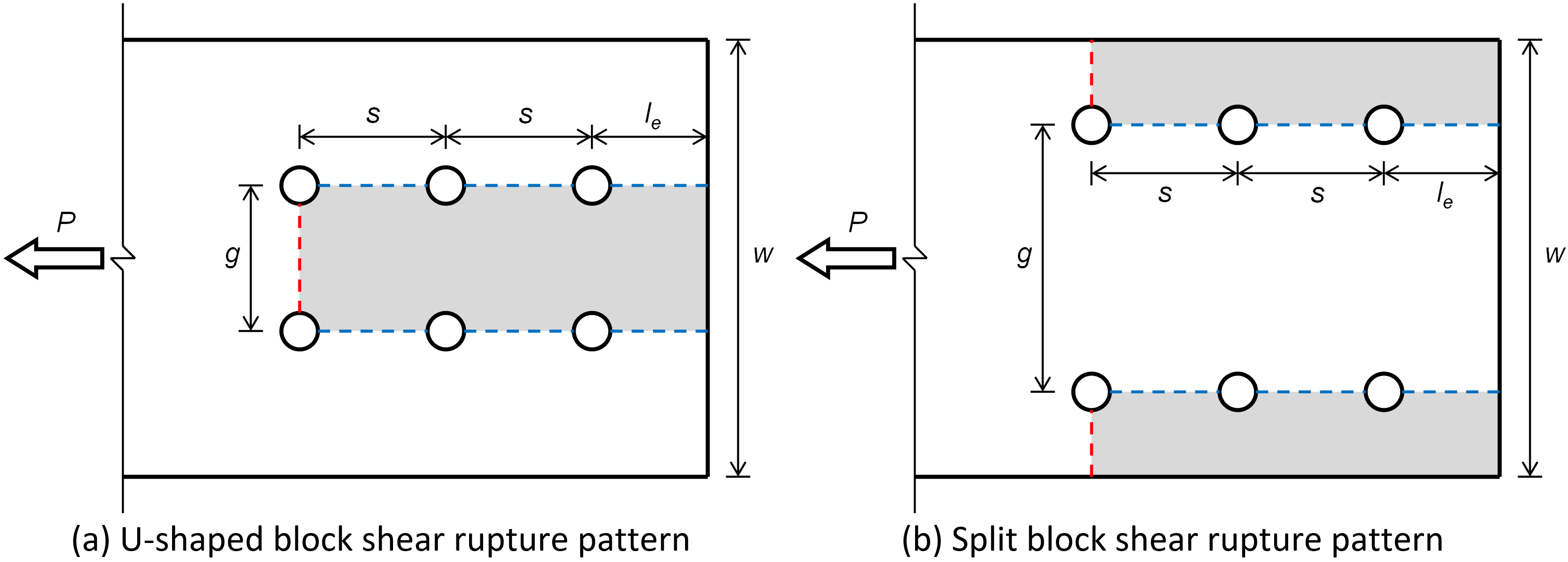
Figure 4 U-shaped and split block shear rupture patterns
To investigate block shear rupture for plates in tension, a simple connection with a 1/2 in. thick plate bolted between two 3/4 in. thick plates was used. All three plates were 12 in. wide. The 3/4 in. thick plates were ASTM A529 Gr 50 (Fy = 50 ksi, Fu = 65 ksi). Two different grades of steel were evaluated for the 1/2 in. thick plate: ASTM A36 (Fy = 36 ksi, Fu = 58 ksi) and ASTM A529 Gr 50 (Fy = 50 ksi, Fu = 65 ksi).
The plates were connected with two lines of three 7/8 in. ASTM F3125 Gr A490 bolts (6 bolts total). For the investigation of the U-shaped rupture pattern, the edge distance, le, was 2 in. and the bolt gage, g, was 2-1/2 in. (resulting in an edge distance perpendicular to the direction of force of 4-3/4 in.). For the investigation of the split rupture pattern, the edge distance, le, was 1-1/2 in. and the bolt gage, g, was 8-1/2 in. (resulting in an edge distance perpendicular to the direction of force of 1-3/4 in.). For both configurations, analyses were performed for 11 values of bolt spacing, s, ranging from 2-1/2 in. to 3-3/4 in.
Three-dimensional views of the connections with a 2-1/2 in. bolt spacing for the U-shaped and split pattern investigations are presented in Figure 5 and Figure 6, respectively.
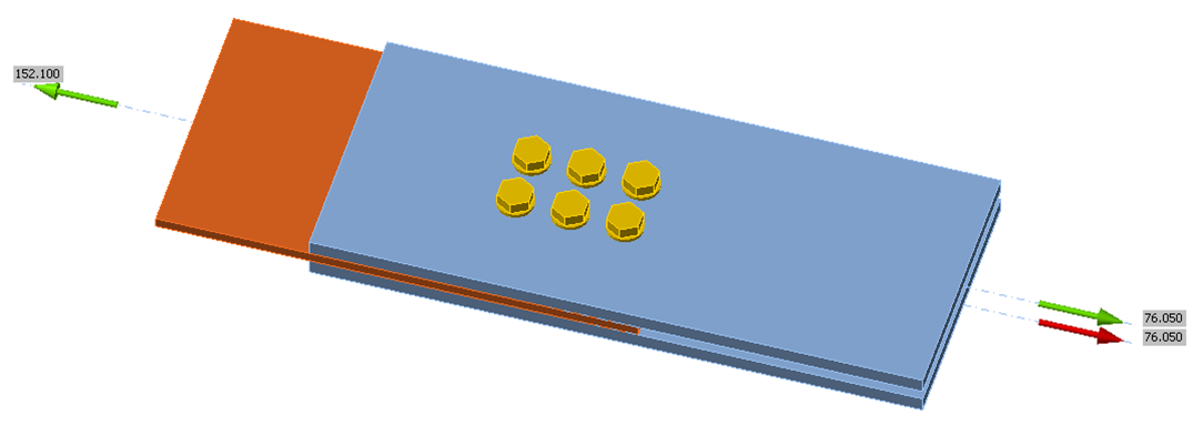
Figure 5 IDEA StatiCa model of connection for U-shaped block shear rupture pattern investigation (bolt spacing, s = 2-1/2 in.)

Figure 6 IDEA StatiCa model of connection for split block shear rupture pattern investigation (bolt spacing, s = 2-1/2 in.)
Comparisons between connection strength according to IDEA StatiCa and the AISC Specification for U-shaped and split block shear rupture patterns are presented in Figure 7 and Figure 8, respectively. The limit states that controlled the traditional calculations and the limits that controlled the IDEA StatiCa analyses are annotated on these figures. Plastic strain distributions for the U-shaped and split block shear rupture investigations are presented in Figure 9 and Figure 10, respectively.
As expected, strength increases with bolt spacing since increasing the bolt spacing increases the shear area. The traditional calculations and the IDEA StatiCa analyses provide similar strengths over the range of bolt spacing for the A36 plate, but the IDEA StatiCa strength exceeds the strength from the traditional calculation for the Grade 50 plate, especially when the bolts are more closely spaced. The reason for this difference is that, unlike the traditional calculations, IDEA StatiCa does not use the tensile strength, Fu. Instead, IDEA StatiCa uses a bi-linear stress-strain relationship with yielding at 0.9Fy and only a small hardening stiffness thereafter. Moving from A36 plate to A529 Gr 50 plate, Fy increases by 39%, but Fu only increases by 12%. Thus, the increase in IDEA StatiCa strength will be approximately 39% while the increase in strength from the design equation will vary between 12% and 39% depending on the relative importance of shear yielding (which increases with bolt spacing for this configuration).
Another difference, albeit a relatively minor one, is that AISC Specification Section B4.3b requires that 1/16 in. be added to the nominal diameter of bolt holes when computing the net area in tension or shear. This adjustment is not made, and the nominal bolt hole diameter is used in IDEA StatiCa when defining the mesh of shell elements representing members and connecting elements.
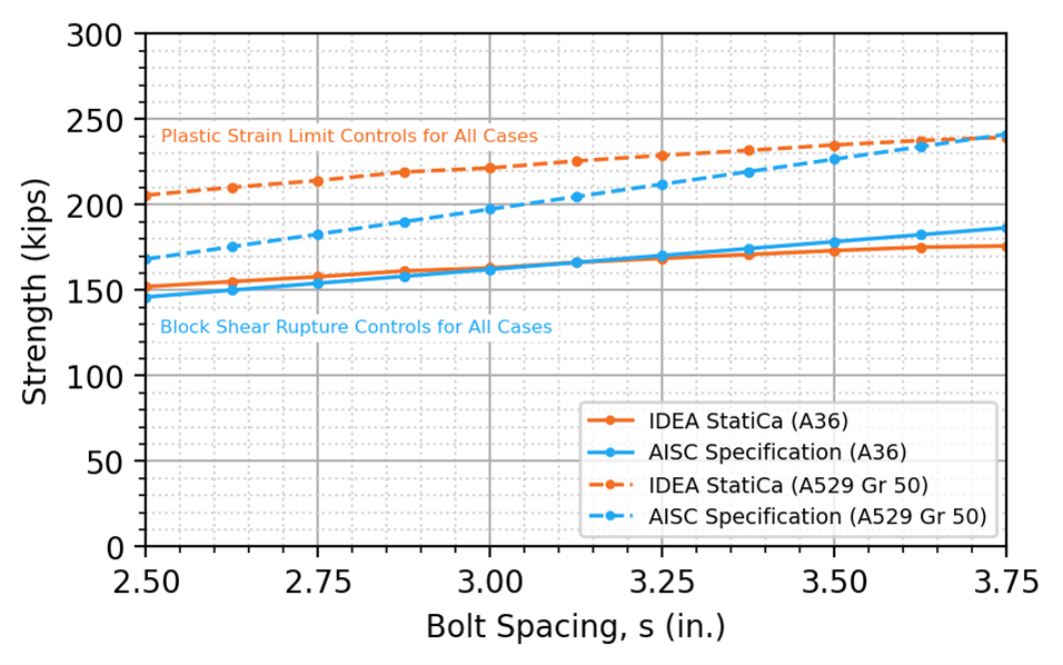
Figure 7 Strength vs bolt spacing, U-shaped block shear rupture
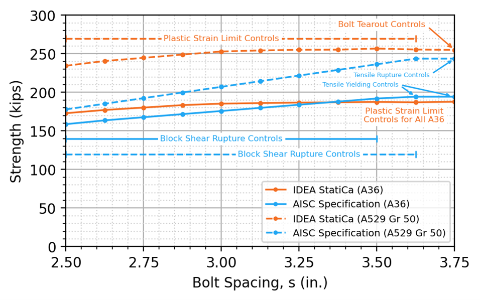
Figure 8 Strength vs bolt spacing, split block shear rupture

Figure 9 Plastic strain distributions, U-shaped block shear rupture
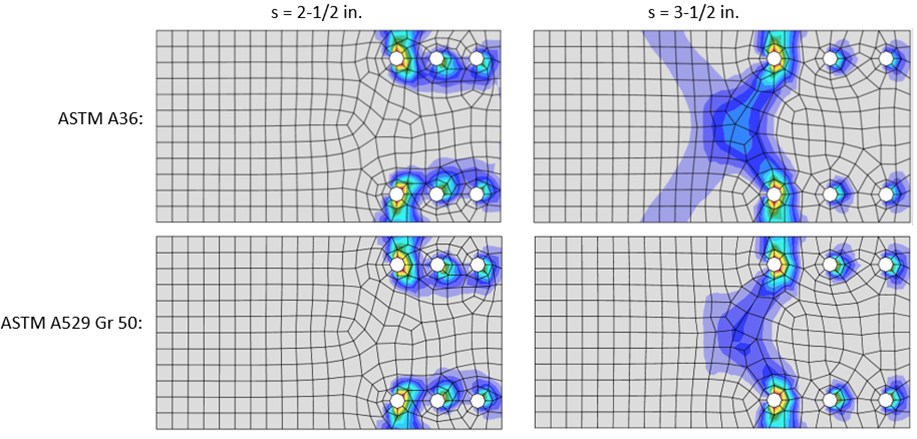
Figure 10 Plastic strain distributions, split block shear rupture
Comparison to Other Strength Equations
To further explore the differences in strength between IDEA StatiCa and the AISC Specification, additional traditional calculation methods are evaluated. A comparison between the connection strength determined from IDEA StatiCa analysis and factored strengths determined from the AISC Specification, CSA S16, and Teh and Deierlein (2017) is presented for A36 and A529 Gr 50 steel, for U-shaped block shear rupture in Figure 11 and Figure 12, and split block shear rupture in Figure 13 and Figure 14.
The strengths from CSA S16 and Teh and Deierlein (2017) are greater than the strengths from the AISC Specification for all cases investigated. The strengths from CSA S16 and Teh and Deierlein (2017) are similar to those from IDEA StatiCa for Grade 50 material and smaller bolt spacing, and greater otherwise. These results indicate that differences between the IDEA StatiCa and the AISC Specification are primarily due to conservativeness in the AISC Specification equation for block shear rupture and not unconservativeness in the IDEA StatiCa analysis.

Figure 11 Comparison to CSA S16 and Teh and Deierlein (2017) for plate in tension, U-shaped block shear rupture (ASTM A36)
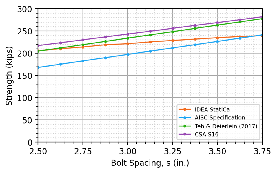
Figure 12 Comparison to CSA S16 and Teh and Deierlein (2017) for plate in tension, U-shaped block shear rupture (ASTM A529 Gr 50)

Figure 13 Comparison to CSA S16 and Teh and Deierlein (2017) for plate in tension, split block shear rupture (ASTM A36)

Figure 14 Comparison to CSA S16 and Teh and Deierlein (2017) for plate in tension, split block shear rupture (ASTM A529 Gr 50)
Effect of Mesh Refinement
IDEA StatiCa uses 8 finite elements around each bolt hole with no option to define more. This number of elements was selected to balance accuracy and computational efficiency. IDEA StatiCa does, however, provide the option to refine the mesh not directly adjacent to the bolt holes. Results from IDEA StatiCa analyses using a refined mesh where the “Number of elements on biggest member web or flange” is set to 24 in the IDEA StatiCa code setup (the default is 12) are presented in Figure 15 and Figure 16 for the U-shaped and split block shear rupture cases, respectively, and Grade 50 material.
For the cases investigated, mesh refinement had minimal effect on the strength of the connection. The primary reason for this is that the maximum plastic strains occurred at the bolt holes (see Figure 9 and Figure 10) where the size of the elements is fixed in IDEA StatiCa regardless of meshing parameters in the code setup. Refining the mesh elsewhere did not significantly impact the results.
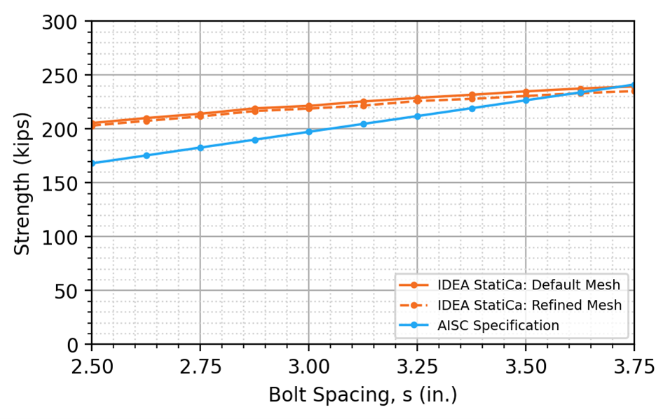
Figure 15 Effect of mesh refinement for plate in tension with U-shaped block shear rupture (ASTM A529 Gr 50)
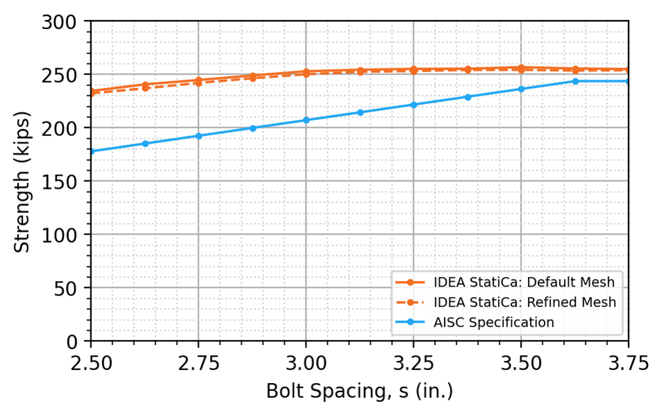
Figure 16 Effect of mesh refinement for plate in tension with split block shear rupture (ASTM A529 Gr 50)
Coped Beams
Block shear rupture is also a commonly controlling limit state for webs of coped beams. To investigate block shear rupture for this case, double-angle cleat connections between a coped beam and girder are evaluated. Connections with one and two vertical rows of bolts (i.e., lines of bolts parallel to the direction of the shear force) were considered.
For the comparisons, the beam is a W24x131 and the girder is a W36x256. Both wide flange shapes conform to ASTM A992 (Fy = 50 ksi, Fu = 65 ksi). The setback between the girder web and beam is 1/2 in. The cope length is 5-3/8 in., the cope depth is 2 in., and a rounding radius of 1/2 in. at the coped corner is used. To isolate failure to the beam web, a strong double-angle cleat connection was chosen. The angles are L6x6x1/2, 21 in. long, and conform to ASTM A529 Gr 50 (Fy = 50 ksi, Fu = 65 ksi). The cleat is welded to the girder web using 3/8 in. fillet welds and bolted to the beam web using 7/8 in. diameter ASTM F3125 Gr A490 bolts. The configuration is shown in Figure 17.

Figure 17 Schematic of the coped beam-to-girder double-angle cleat connection
Analyses were performed on connections with 2 to 7 bolts in each vertical row. The bolt spacing is 3 in. in the vertical and horizontal directions for all connections. For the connections with one vertical row of bolts, the vertical and horizontal edge distance is 1-1/2 in. For the connections with two vertical rows of bolts, the vertical and horizontal edge distance is 1-1/8 in. These dimensions are shown in Figure 18. Three-dimensional views of the connections are presented in Figure 19.
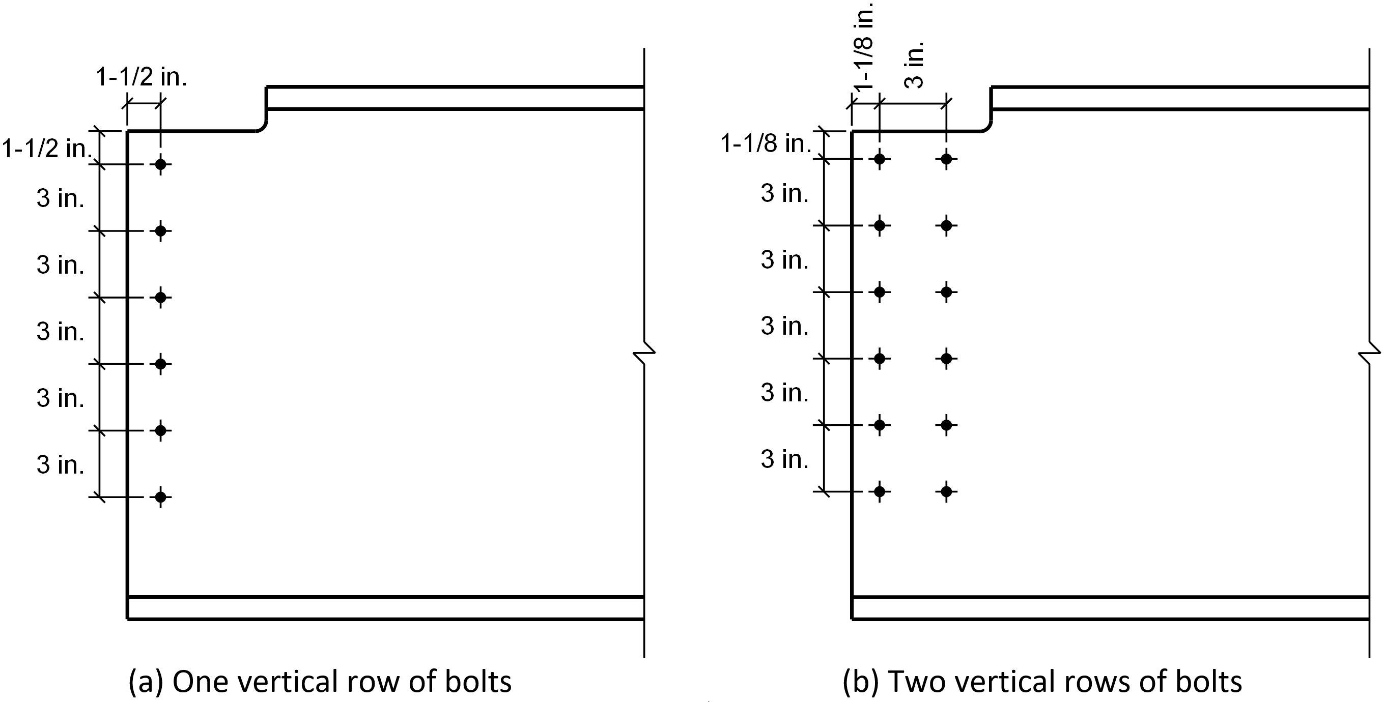
Figure 18 Bolt spacing and edge distances for the coped beam connections
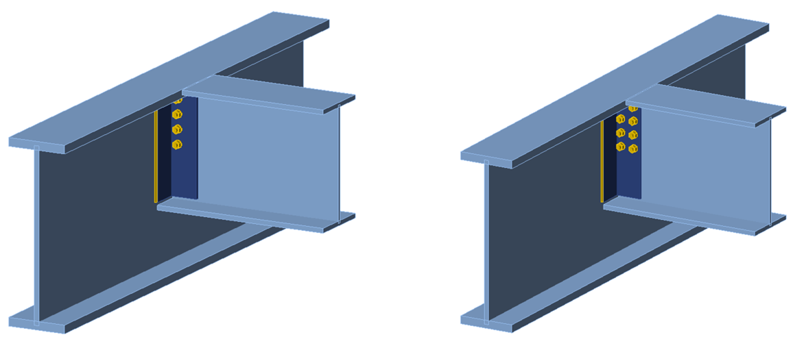
Figure 19 Three-dimensional view of the coped beam connections
As is customary in U.S. practice, the point of zero moment is assumed to be at the face of the support (i.e., the face of the girder web). This assumption was realized in IDEA StatiCa by setting the location of the force to half the girder web thickness from the node. For the traditional calculations, applicable limit states other than block shear rupture were evaluated on the coped beam but were not controlled. These limit states are flexural local buckling of the coped section, shear yielding, shear rupture, bolt shear rupture, and bearing and tearout at the bolt holes. Connection strength vs number of bolts in a vertical row is presented in Figure 20 and Figure 21 for the connections with one and two vertical rows of bolts, respectively. The plastic strain distributions for connections with 3 and 6 bolt rows are presented in Figure 22 and Figure 23 for connections with one and two vertical rows of bolts, respectively.
For both one and two vertical rows of bolts, the IDEA StatiCa strength is less than the AISC Specification strength when each vertical row has only two bolts. However, as the number of bolts in each vertical row increases, the IDEA StatiCa strength increases faster than the AISC Specification strength resulting in higher strengths from IDEA StatiCa than from the AISC Specification equations.
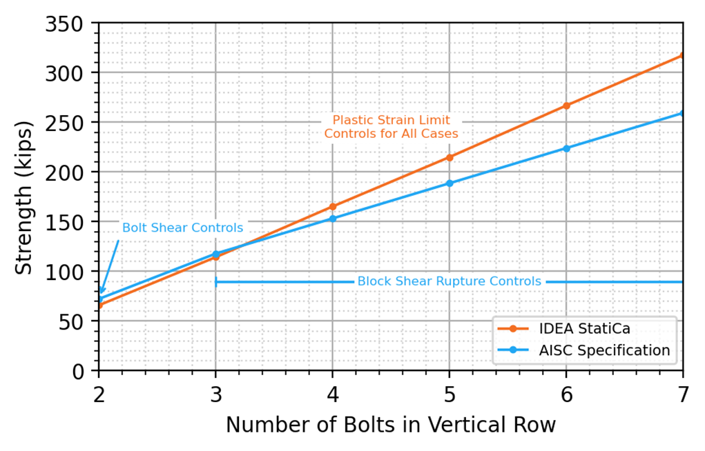
Figure 20 Strength vs number of bolt rows for a connection with one vertical row of bolts

Figure 21 Strength vs number of bolt rows for a connection with two vertical rows of bolts
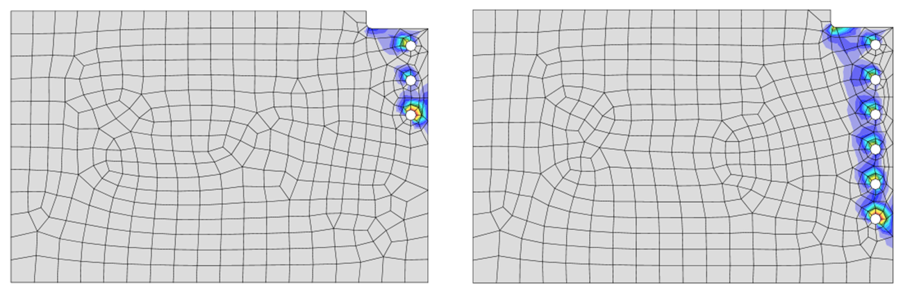
Figure 22 Plastic strain distributions for connection with one vertical row of bolts (3 and 6 bolts in each row)
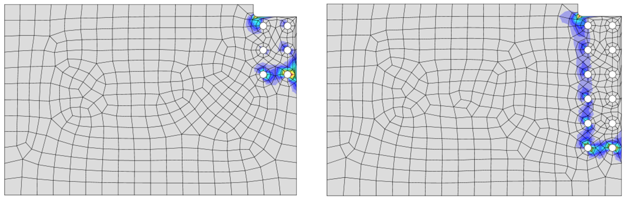
Figure 23 Plastic strain distributions for connection with two vertical rows of bolts (3 and 6 bolts in each row)
Comparison to CSA S16
As with the plates in tension, IDEA StatiCa gives higher strengths than the traditional calculations for many of the connections investigated. To further explore these differences, the results are also compared to strengths from the Canadian standard, CSA S16. The equation proposed by Teh and Deierlein (2017) is not evaluated for these coped beam equations since Teh and Deierlein proposed their equation only for plates in tension. A comparison of strengths for the connections with one and two vertical rows of bolts described above is presented in Figure 24 and Figure 25, respectively.
The strength, according to CSA S16, is greater than the strength according to IDEA StatiCa and the AISC Specification for all the connections with a single vertical row of bolts. For the connections with two vertical rows of bolts, the strength according to CSA S16 is greater than the strength according to the AISC Specification, but less than the strength according to IDEA StatiCa with 4 or more bolts in each vertical row. As with the plates in tension, these results indicate that differences between the IDEA StatiCa and the AISC Specification are primarily due to conservativeness in the AISC Specification equation for block shear rupture and not unconservativeness in the IDEA StatiCa analysis.
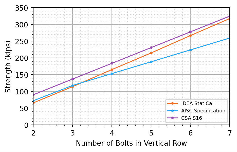
Figure 24 Comparison to CSA S16 for coped beam connection with one vertical row of bolts
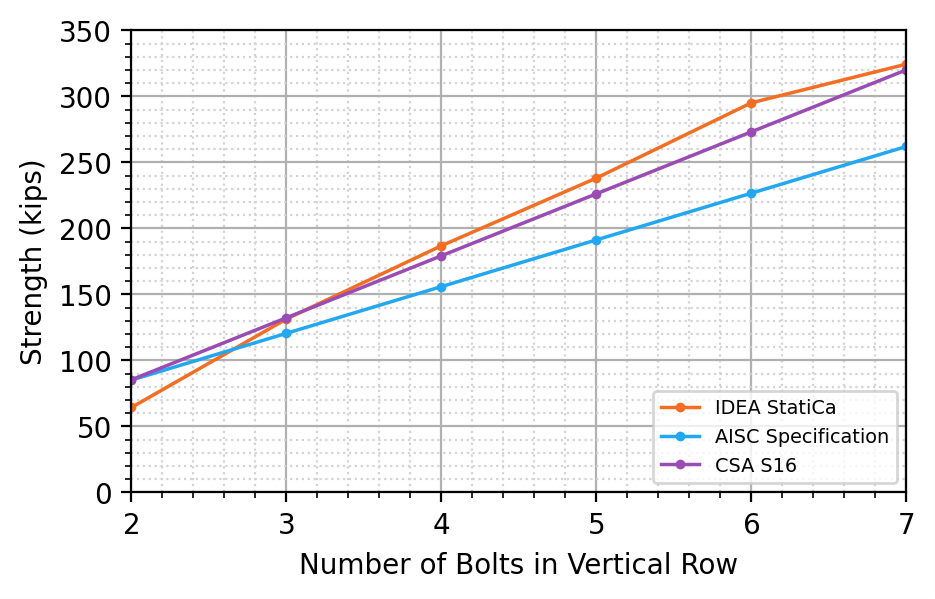
Figure 25 Comparison to CSA S16 for coped beam connection with two vertical rows of bolts
Effect of Position of Applied Force
Simple shear connections, such as the double angle cleat connection investigated here, have some rotational restraint and the location of the point of zero moment (i.e., the “pin”) will depend on the relative stiffness of the beam, connection, and support. As noted previously, it is customary in United States practice to assume the point of zero moment in a simple shear connection is at the face of the supporting member (i.e., the face of the girder web for a beam-to-girder connection). This assumption is not explicitly considered in the block shear rupture equation in the AISC Specification. In contrast, the assumption of the point of zero moment must be explicitly defined in IDEA StatiCa and the choice affects the stresses and strains in the beam web. IDEA StatiCa allows for the point of zero moment to be manually adjusted by defining the position of applied force along the longitudinal axis of the beam. The option of “Forces in Bolts” places the applied forces at the centroid of the bolt group (for this case where the only applied load is shear, the point of zero moment would also be at the centroid of the bolt group). For all coped beam analyses in this report except for those described in this section, the position of the applied force was set equal to half of the girder web thickness from the node (i.e., the face of the supporting member).
To investigate the effect of the position of applied force, additional analyses were performed on the connections with one vertical row of bolts. The additional analyses were performed with “Forces in Bolts”. The results of these analyses are compared to the previous results from analysis with forces at the face of the girder web in Figure 26.
When the point of zero moment is at the centroid of the bolt group (i.e., “Forces in Bolts”), the distribution of stresses and bolt forces is different, resulting in higher strengths and different controlling limits. With 2 through 6 bolts in the vertical row, the strengths are higher and tearout of the top bolt controls. With 7 bolts in a vertical row, the strength is higher but plastic strain limit in the beam web still controls. The increase in strength is physically realistic since the eccentricity of the load on the failure surfaces is reduced with the point of zero moment at the centroid of the bolts. The AISC Specification equation only roughly captures this effect with the term Ubs.
While the assumed location of the point of zero moment within a simple shear connection is a choice made by the engineer, it should be consistent with the choices made in the overall structural analysis of the frame to ensure equilibrium is satisfied.
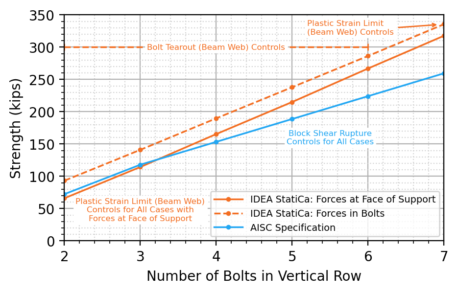
Figure 26 Comparison between position of applied force applied at centroid of bolt group vs face of support
Comparison to Experimental Results
The comparisons presented in this study have shown that the strength of connections according to IDEA StatiCa often exceeds that of the traditional calculations according to the AISC Specification when block shear rupture is the controlling limit state. To expand on the investigation, this section includes comparisons to previously published experimental results.
For these comparisons, the measured material and geometric properties reported by the experimentalists were used in the calculations and analyses. For the traditional calculations, resistance factors were not applied. For the IDEA StatiCa analyses, the resistance factors for material, bolts, and welds were set to 1.0 in the code setup.
Plates in Tension – Hardash and Bjorhovde 1984
Hardash and Bjorhovde (1984) performed tensile tests of bolted plate connections. Twenty-eight specimens were loaded in tension through two lines of bolts. The specimens all failed in block shear rupture with a U-shaped pattern like that shown in Figure 4a. Of the twenty-eight specimens tested, all except specimen No. 18 were cut from 0.237 in. thick steel plate with yield stress and ultimate stress obtained from coupon testing of 33.2 and 46.9 ksi, respectively. Specimen No. 18 was cut from a higher strength steel plate, with a yield stress of 49.5 ksi, ultimate stress of 64.5 ksi, and thickness of 0.253 in. The number of bolts in each line, other dimensions shown in Figure 4a, and the bolt hole diameter, dh, are listed for each specimen in Table 1.
The twenty-eight specimens were modeled using measured material and geometric properties and analyzed in IDEA StatiCa. The strength of each connection was also computed using the nominal strength equation for block shear rupture in the AISC Specification with measured material and geometric properties (the resistance factor was not applied). The results of the comparison between experimental strength, IDEA StatiCa strength, and AISC Specification strength are presented in Table 2 and Figure 27.
The strength according to the AISC Specification equation is less than the experimental strength for all connections in this group with an average ratio of 0.81. This result indicates that the design equation is conservative since the AISC strength uses measured material and geometric properties and does not include the resistance factor of 0.75. The strength according to IDEA StatiCa is also less than the experimental strength for all connections and the average ratio is even lower at 0.75. However, this does not indicate greater conservatism for IDEA StatiCa than for the AISC Specification since IDEA StatiCa uses a material strength reduction factor of 0.9 and not the resistance factor for block shear rupture of 0.75. Nonetheless, assuming that 0.75 is the appropriate strength reduction to achieve the target level of reliability, the IDEA StatiCa results are sufficiently conservative for these specimens given the average strength ratio, PIDEA/Pexp, of 0.75 and the 0.9 material strength reduction that would be applied in design.
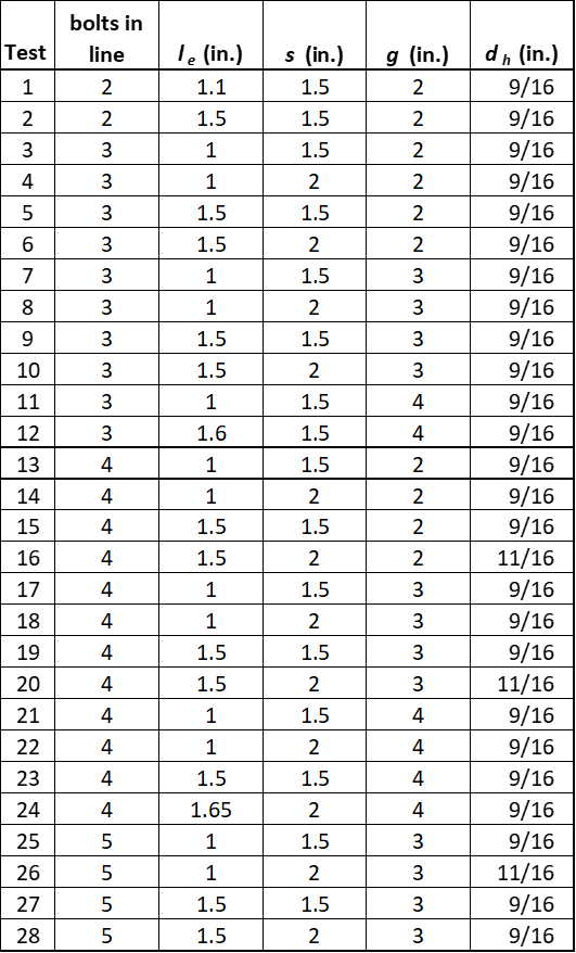
Table 1 Specimen data from the Hardash and Bjorhovde (1984) experimental investigation
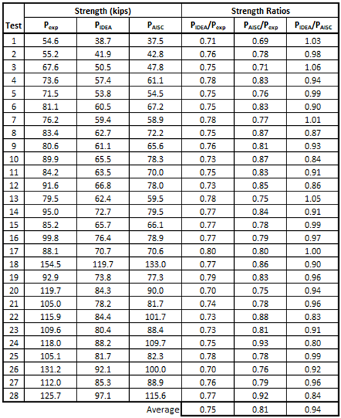
Table 2 Comparison to the Hardash and Bjorhovde (1984) experimental investigation

Figure 27 Comparison to the Hardash and Bjorhovde (1984) experimental investigation
Coped Beams – Ricles and Yura 1983
Ricles and Yura (1983) tested full-scale bolted-web connections with two vertical rows of bolts. The seven coped beam specimens and one uncoped beam specimen were connected to a column stub with a bolted double-angle connection and loaded until failure. The configurations for the eight test specimens are presented in Figure 28. The seven coped specimens (18-10, 18-11, 18-12, 18-16, 18-17, 18-18, and 18-19) were selected for comparison. They all failed in block shear rupture. Dimensions of the specimens are shown in Figure 28. Measured material properties and web thickness, tw, are listed in Table 3. All bolt holes were 13/16 in. diameter. One specimen, 18-11, had slotted holes that were 13/16 in. by 15/16 in. with the long axis perpendicular to the direction of force. The slotted holes of this specimen were modeled in IDEA StatiCa as standard holes. The results of the comparison are presented in Table 4 and Figure 29.
The strength according to the AISC Specification is, on average, equal to the experimental strength although some variation is seen among the various specimens. The strength according to IDEA StatiCa is significantly lower than the experimental strength and the strength according to the AISC Specification. The average strength ratio, PIDEA/Pexp, is 0.68, indicating that even after the different resistance factors are applied, conservatism in the IDEA StatiCa results will remain.
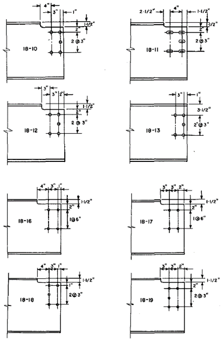
Figure 28 Configurations of test specimens for the Ricles and Yura experimental investigation (Ricles and Yura, 1983)

Table 3 Specimen data from the Ricles and Yura (1983) experimental investigation
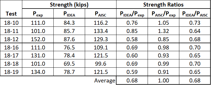
Table 4 Comparison to the Ricles and Yura (1983) experimental investigation

Figure 29 Comparison to the Ricles and Yura (1983) experimental investigation
Coped Beams – Franchuk et al. 2003
Franchuk et al. (2003) tested full-scale bolted-web connections in coped beams including 14 specimens with a single vertical row of bolts and 3 specimens with two vertical rows of bolts. All but one specimen was coped at the top flange only and failed in block shear rupture. Specimen D2 was coped at the top and bottom flanges and failed in shear rupture of the beam web. The geometric and material properties for the 17 specimens are presented in Table 5 and Figure 30.
The 17 specimens were modeled and analyzed in IDEA StatiCa for comparison to the experimental strength and to the strength computed according to the AISC Specification. The results of the comparison are presented in Table 6 and Figure 31.
The strength results for these specimens are like those from the other studies. The strength according to the AISC Specification is somewhat conservative relative to the experimental results and the IDEA StatiCa strengths are lower than those from the AISC Specification.
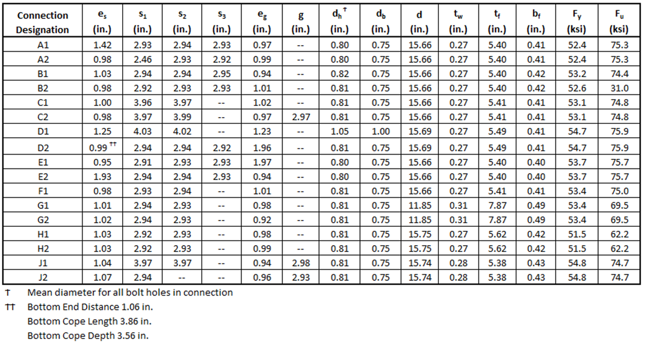
Table 5 Specimen geometric and material properties for the Franchuk et al. (2003) experimental investigation
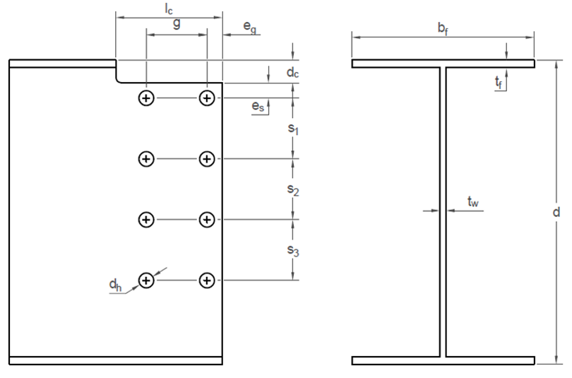
Figure 30 Specimen dimensions for the Franchuk et al. (2003) experimental investigation
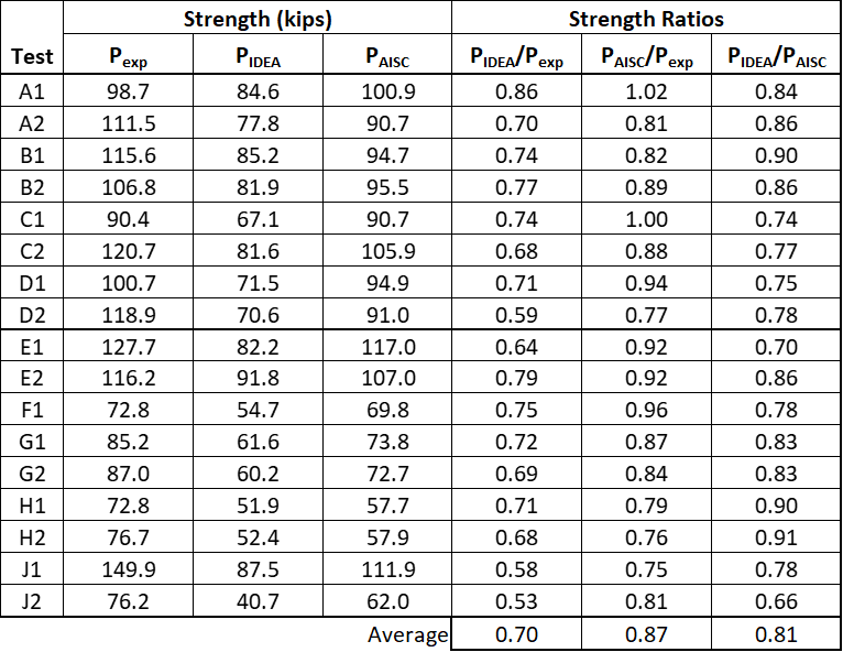
Table 6 Comparison to the Franchuk et al. (2003) experimental investigation
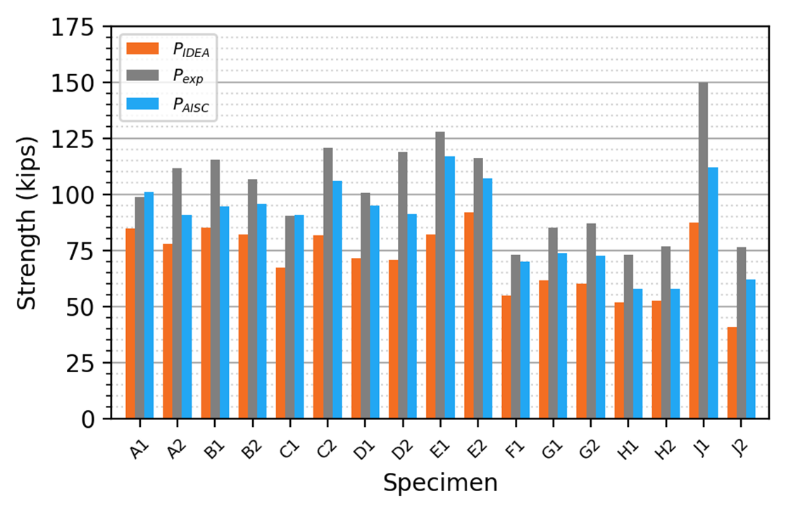
Figure 31 Comparison to the Franchuk et al. (2003) experimental investigation
Summary
This study compares the evaluation of the limit state of block shear rupture in bolted structural steel connections by traditional calculation methods used in US practice and IDEA StatiCa. Key observations from the study include:
- The block shear rupture strength of connections in IDEA StatiCa was found in several cases to be greater than the strength by traditional calculations according to the AISC Specification.
- The comparison between strengths from IDEA StatiCa and the AISC Specification is strongly dependent on the ratio of tensile strength to yield strength (Fu/Fy) of the connected material.
- Research by others, including Teh and Deierlein (2017) and Dhanuskar and Gupta (2019), has shown that the AISC Specification equations for block shear rupture can be conservative.
- Block shear rupture strength according to IDEA StatiCa is accurate or conservative in comparison to the Canadian standard and the design equation proposed by Teh and Deierlein (2017).
- In comparison to a range of physical experiments, strengths from IDEA StatiCa were found to be generally conservative even when considering the difference between the resistance factor applied to block shear rupture in the AISC Specification and the material strength reduction factor applied in IDEA StatiCa.
- IDEA StatiCa does not permit refinement of the mesh around bolt holes. Refinement of the mesh elsewhere had minimal effect on the strength of the connections investigated.
References
AISC (2022), Specification for Structural Steel Buildings, American Institute of Steel Construction, Chicago, IL.
AISC (2017), Steel Construction Manual, 15th Edition, American Institute of Steel Construction, Chicago, IL.
CSA (2019), Design of Steel Structures, Canadian Standards Association, Toronto, Ontario.
Dhanuskar, J.R., and Gupta, L.M. (2019), “Behaviour of Block Shear Failure in Different Connections,” Iranian Journal of Science and Technology, Transactions of Civil Engineering, Vol. 44, pp. 847-859
Franchuk, C.R., et al. (2003), “Experimental Investigation of Block Shear Failure in Coped Steel Beams,” Canadian Journal of Civil Engineering, Vol. 30, pp. 871-881
Hardash, S.G. and Bjorhovde, R. (1984) “Gusset Plate Design Utilizing Block-Shear Concepts,” Research Report, Dept. of Civil Engineering, Univ. of Arizona-Tucson.
Ricles, J.M., Yura, J.A. (1983), “Strength of Double-Row Bolted-Web Connections,” Journal of Structural Engineering, ASCE, Vol. 109, pp. 126-142
Teh, L.H. and Deierlein, G. (2017), “Effective Shear Plane Model for Tearout and Block Shear Failure of Bolted Connections,” Engineering Journal, AISC, Vol. 54, pp. 181 – 194.
Teh, L.H. and Uz, M.E. (2015), “Block Shear Failure Planes of Bolted Connections—Direct Experimental Verifications,” Journal of Constructional Steel Research, Vol. 111, pp. 70–74.
Teh, L.H. and Yazici, V. (2013), “Block Shear Capacity of Bolted Connections in Hot-Rolled Steel Plates,” Connection Workshop VII, European Convention for Constructional Steelwork Task Committee 10, pp. 91–100.