Structural design of a steel beam (EN)
New project
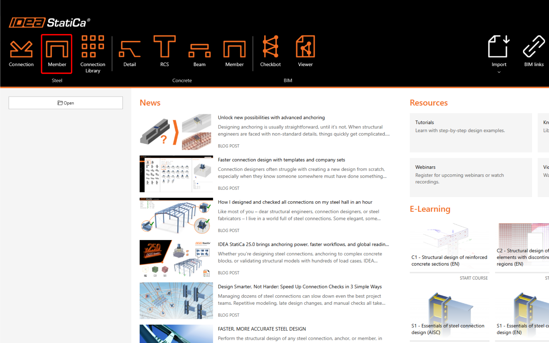
Start by launching IDEA StatiCa and selecting the Member application (download the latest version).
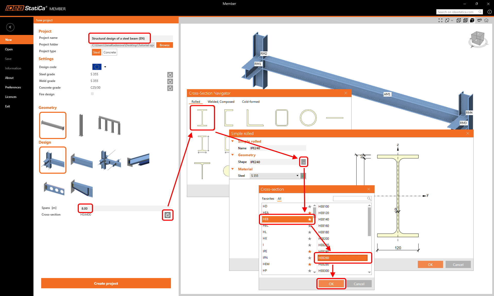
Create a New project (left side bar) and type in the name. Use the beam geometry and use the design with the related members. Set the span to 8.0 m, select the cross-section HEB 260 for the beam, and click Create project.
Analyzed member
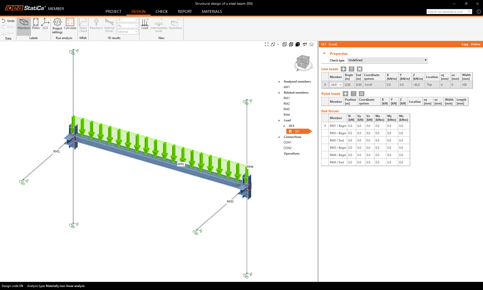
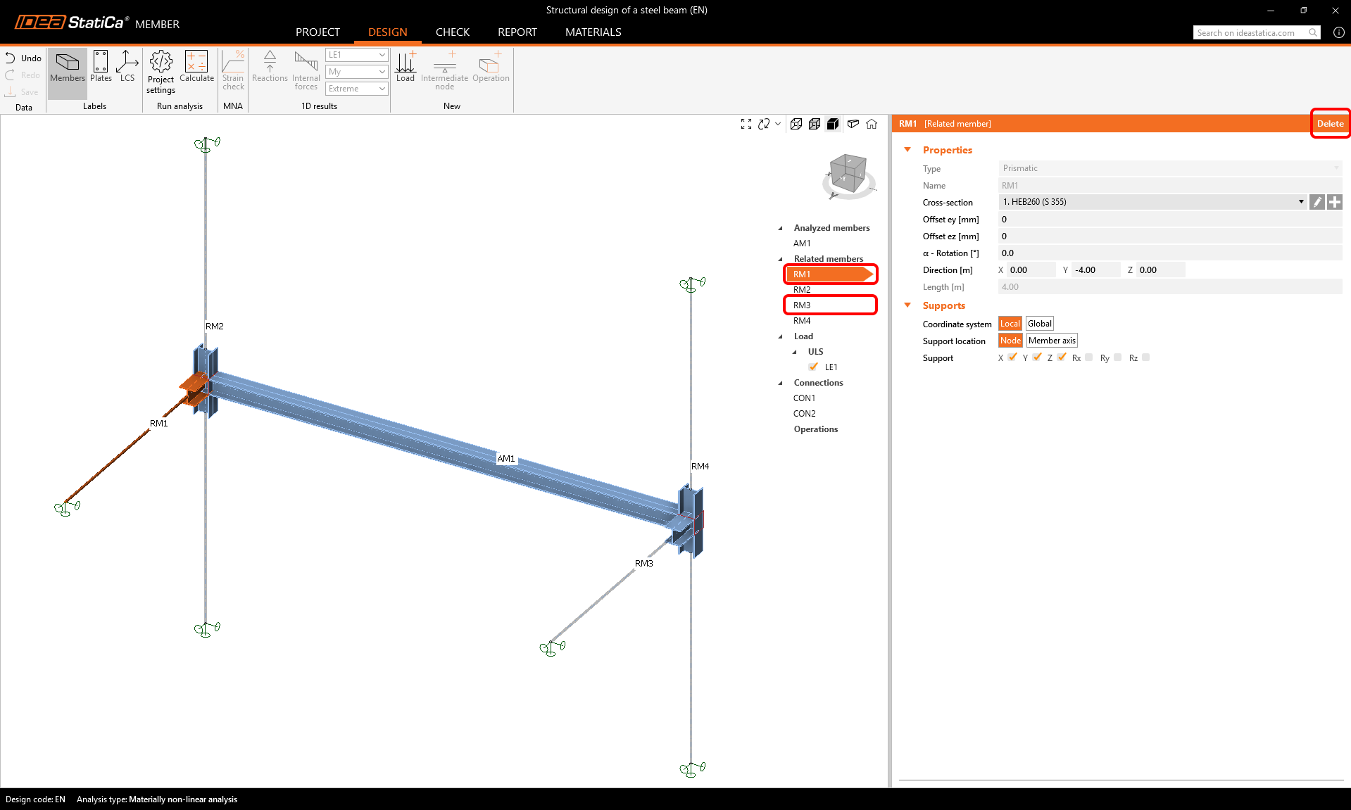
In this example, you have only one analyzed member - AM1, which was created by the template.
Related members
Four related members were also created automatically. However, we only need to keep the two columns. The other two framing beams can be deleted to finalize the arrangement.
Select and delete RM1 and RM3 members.
Loads
Define the dead load on the beam as the Line load and set its parameters.
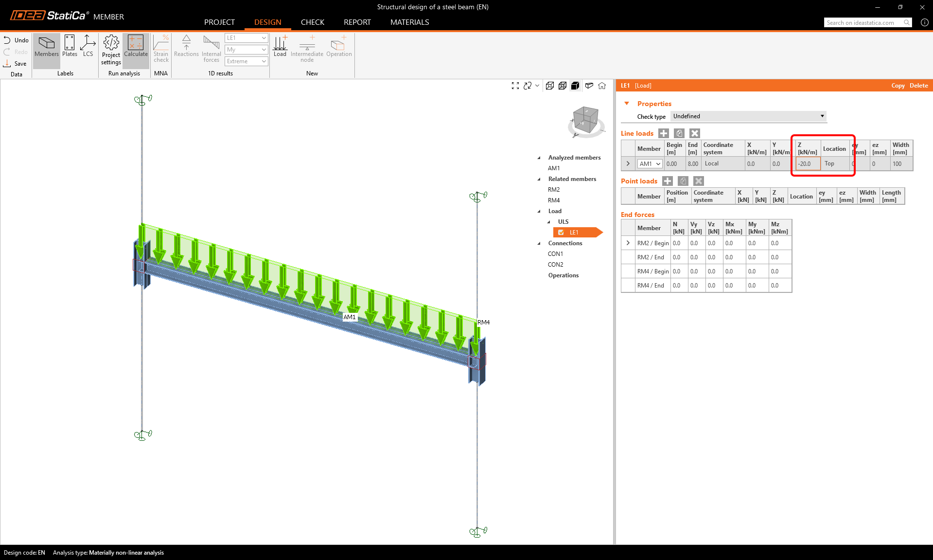
Edit the value of the ULS/LE1 load to -20 kN/m in the z direction acting on the top flange.
Connections
To define the connections, select the CON1 item and then Edit connection.
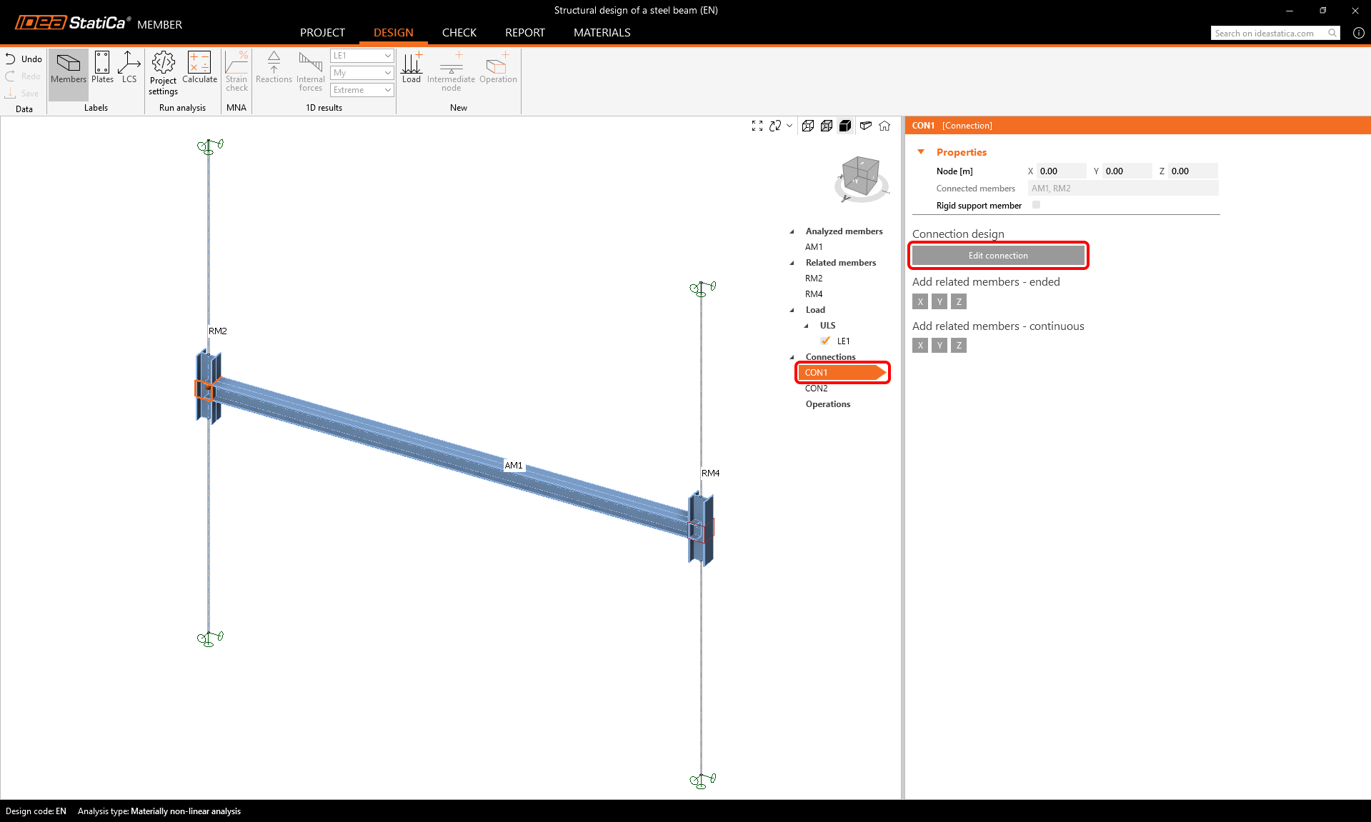
There are more ways we can model this simple connection:
- Using an endplate operation
- Using an example from the Connection Library
We will search for a suitable template in the Connection Library - select the Propose button.
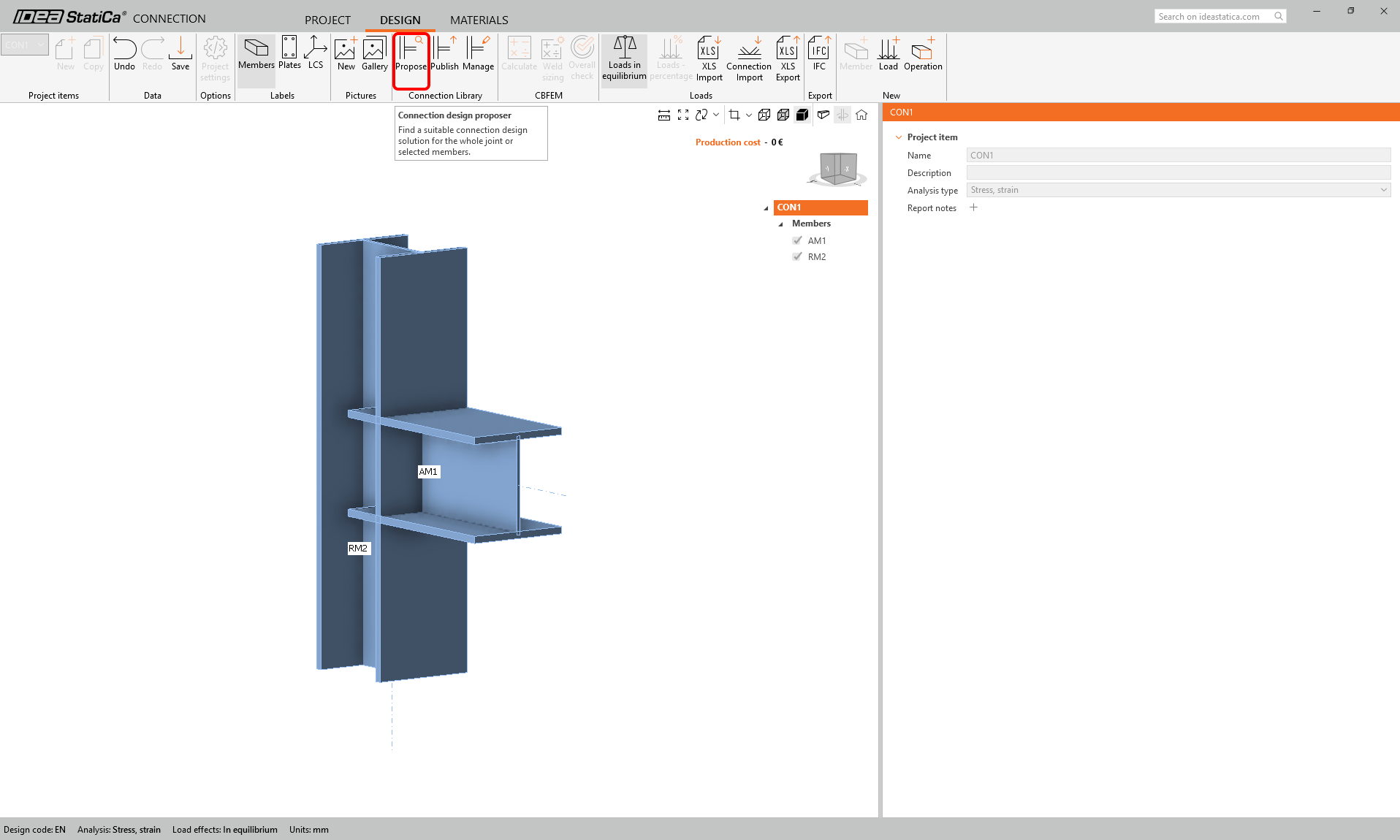
Scroll down through the library and find this design:
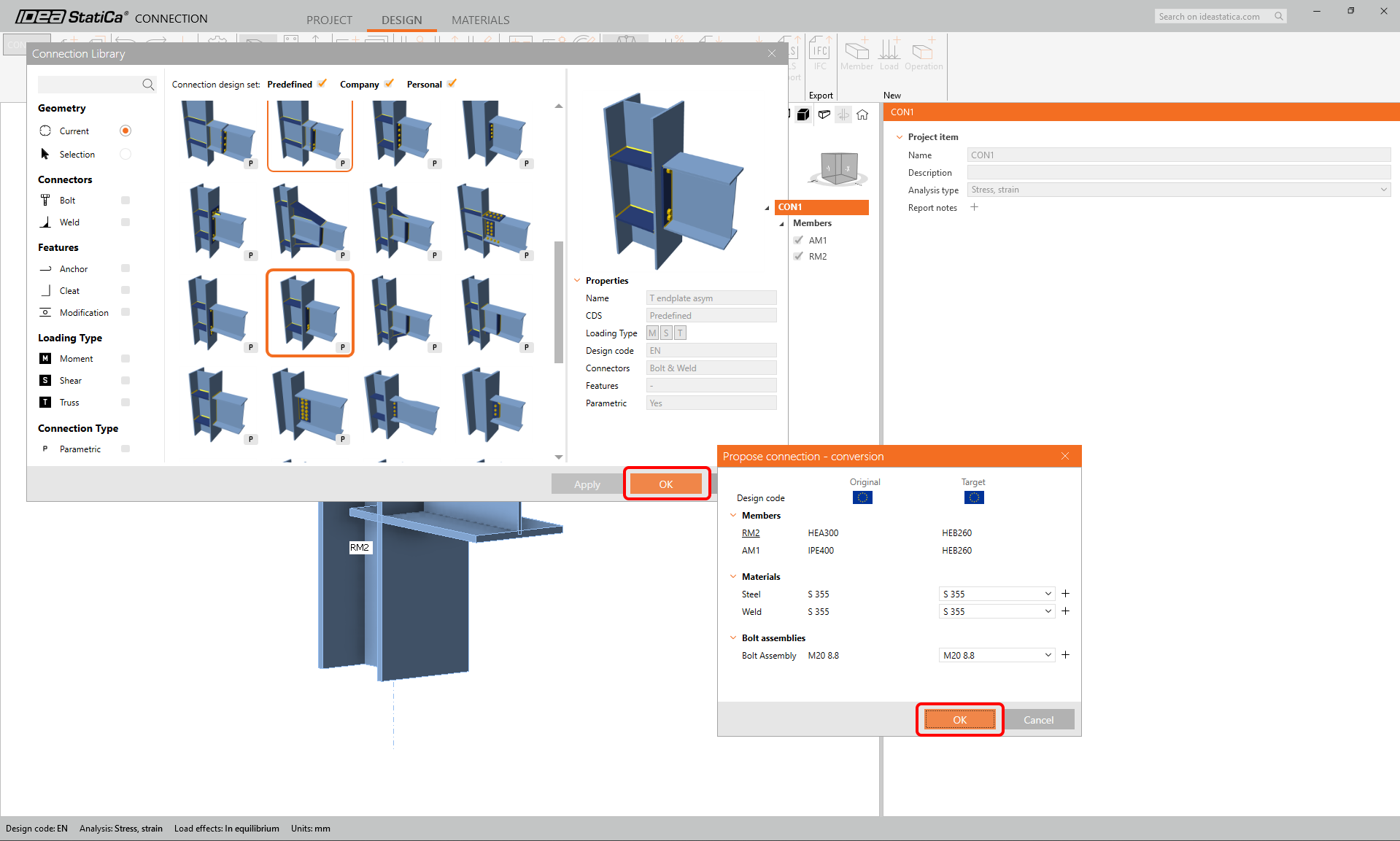
Change the parameters of the parametric template: 2 top rows, 2 bottom rows, bolt column distance 160 mm, first row, bolt spacing, and bolt edge distance - all 50 mm. The bolt type and size M16 8.8. And uncheck the stiffener option.
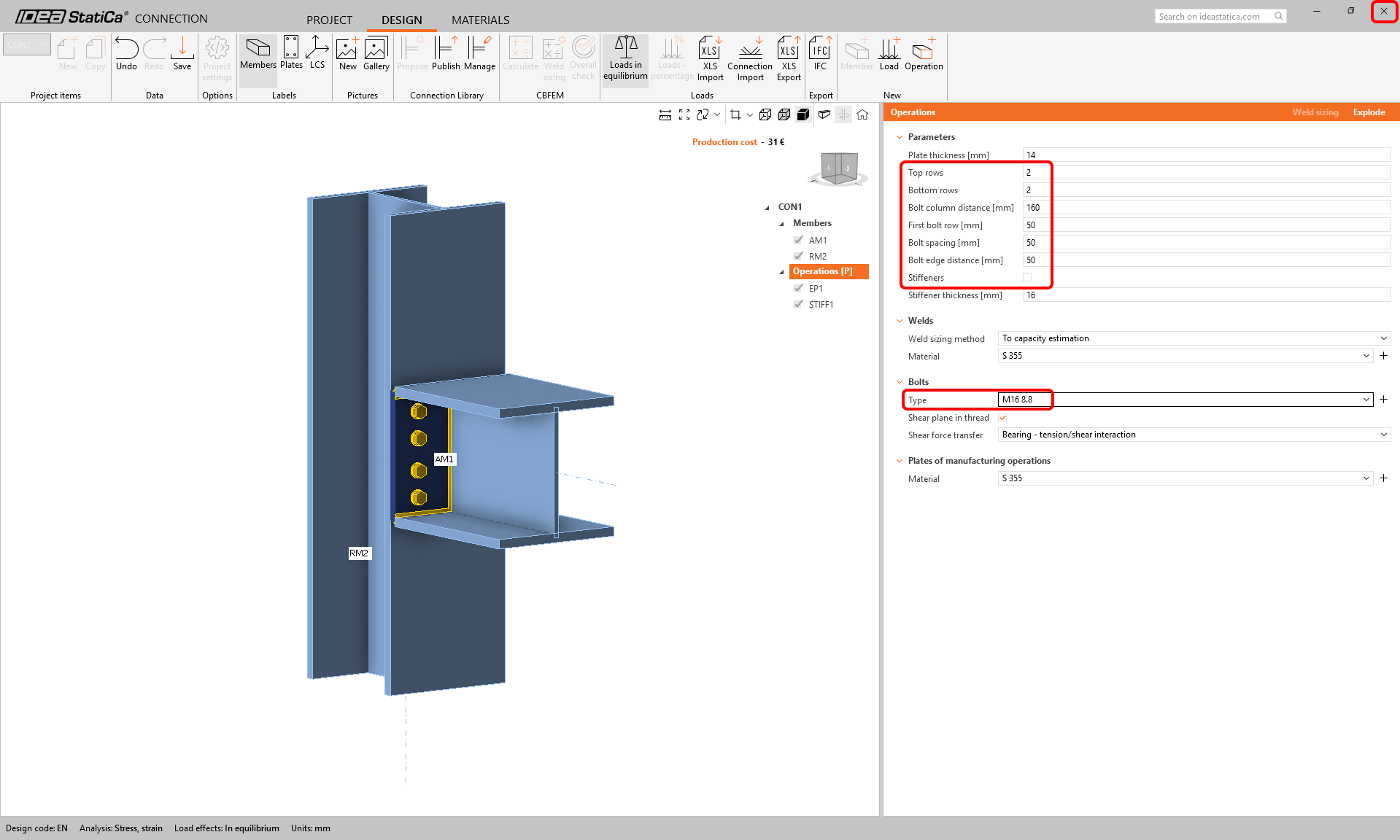
Save and close the connection design and go back to the Member project.
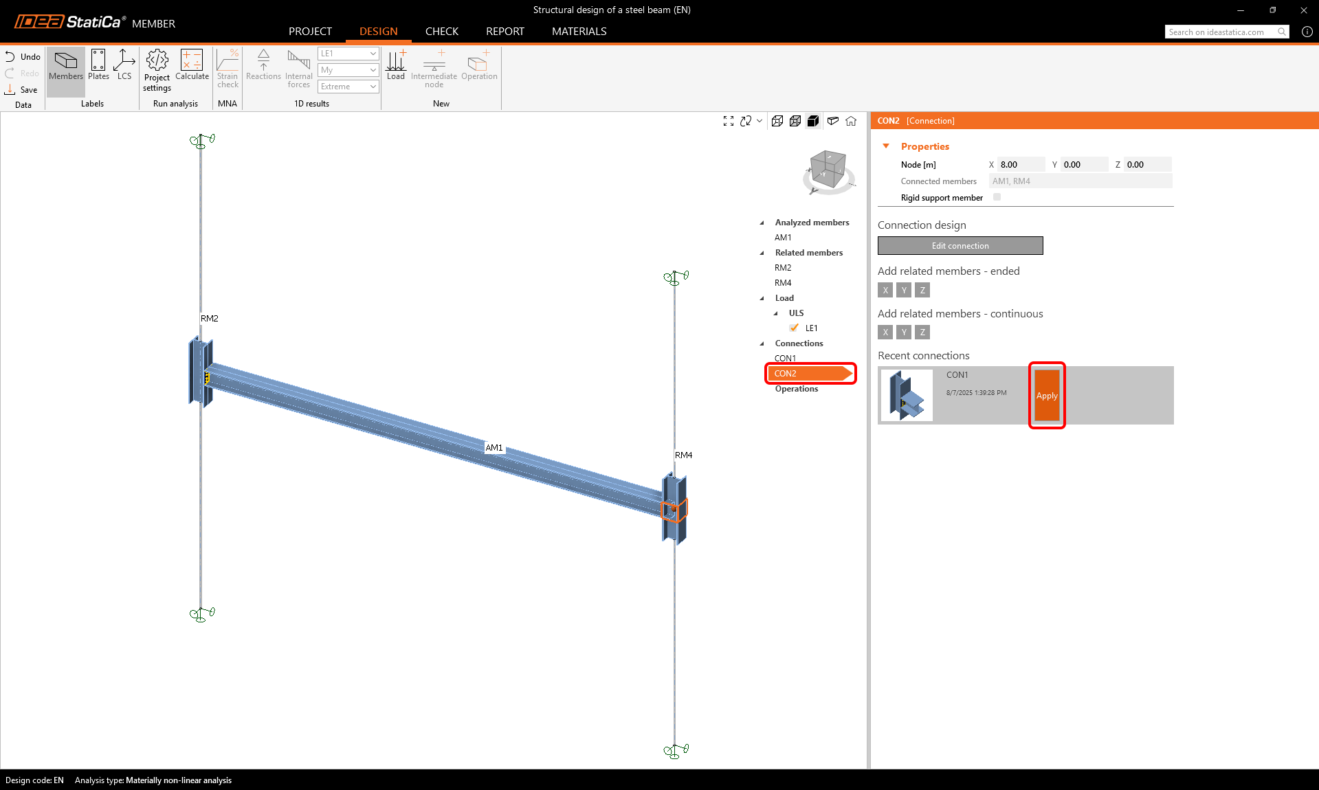
To design the second connection, select connection CON2 and click Apply to copy the offered design from connection CON1.
Check
There are three types of analyses that follow one another.
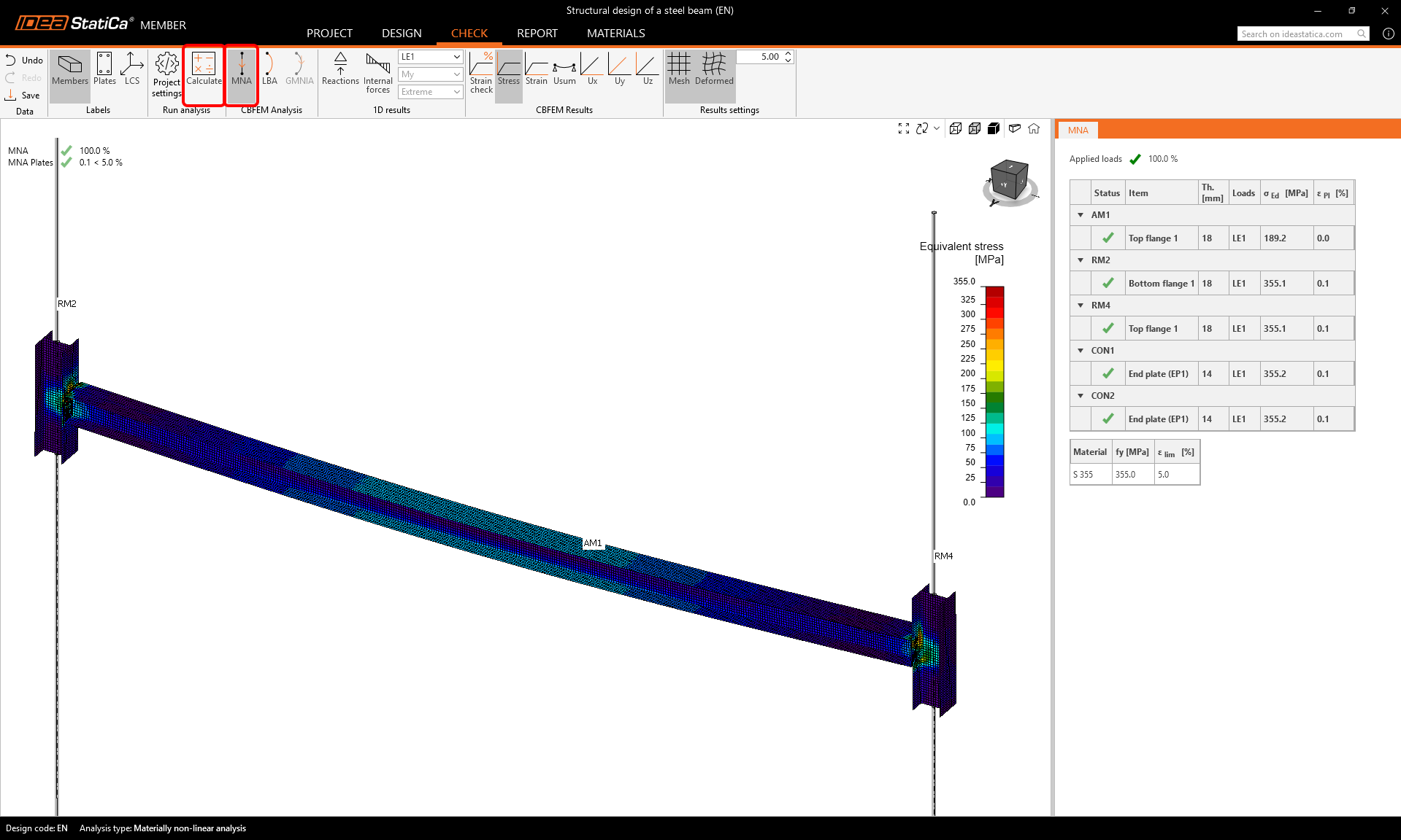
First, start the Materially non-linear analysis (MNA). Select the Tab Check, MNA, and click Calculate.
You can visually check the stress distribution over the beam by clicking on the button Stress in the upper ribbon and selecting Mesh, Deformed to display the deformed shape.
The second step is to perform the Linear Buckling Analysis (LBA) and click Calculate.
Go through the different buckling modes in the rows of the LBA table in the results.
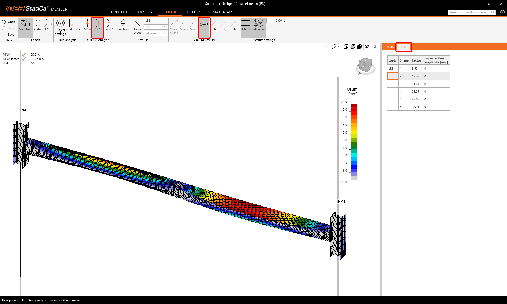
As you see, the first two buckling factors are smaller than 15, so in this case, Geometrically and materially nonlinear analysis with imperfections (GMNIA) should be performed. For more information, please see the Theoretical background.
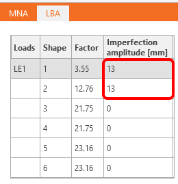
For the GMNIA, you have to set the imperfections (amplitudes of initial geometrical imperfections).
We enter the values 0.5 x L/300 = 0.5 x 8000 mm/300 = 13 mm.
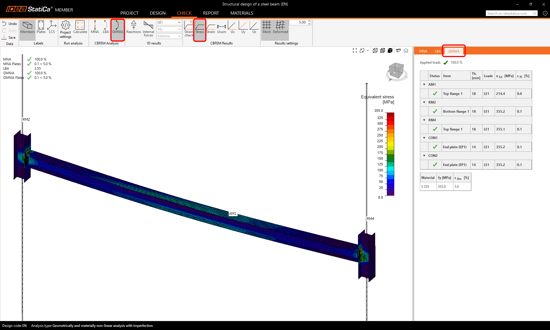
Start the Geometrically and Materially Nonlinear Analysis with Imperfection (GMNIA) calculation by selecting GMNIA and clicking Calculate.
The results show that the member's dimensions are sufficient even with the initial imperfections, and it passes the code checks, taking into account also the stability loss risk.
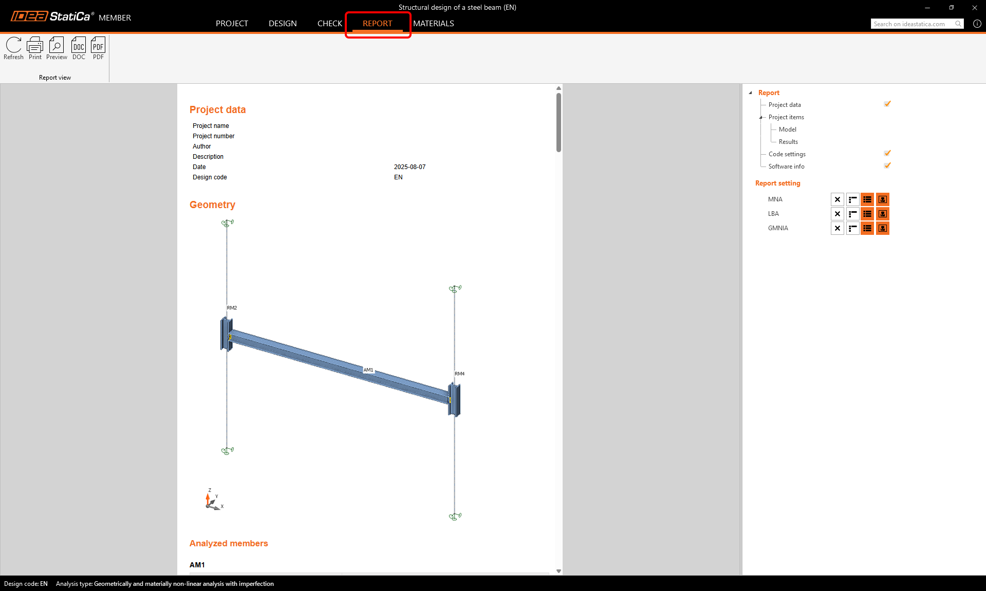
Report
At last, go to the Report tab. IDEA StatiCa offers a customizable report to print out or save in an editable format.