Calcul structurel d'une poutre en acier (EN)
Nouveau projet
Commencez par lancer IDEA StatiCa et sélectionnez l'application Member (téléchargez la dernière version).
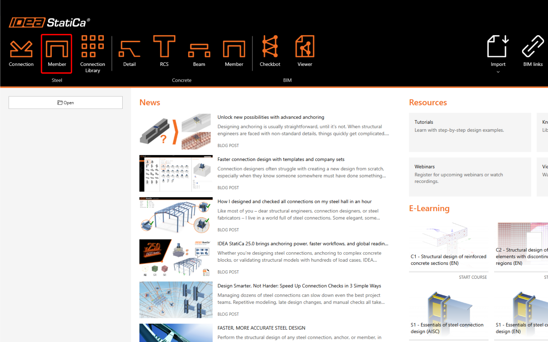
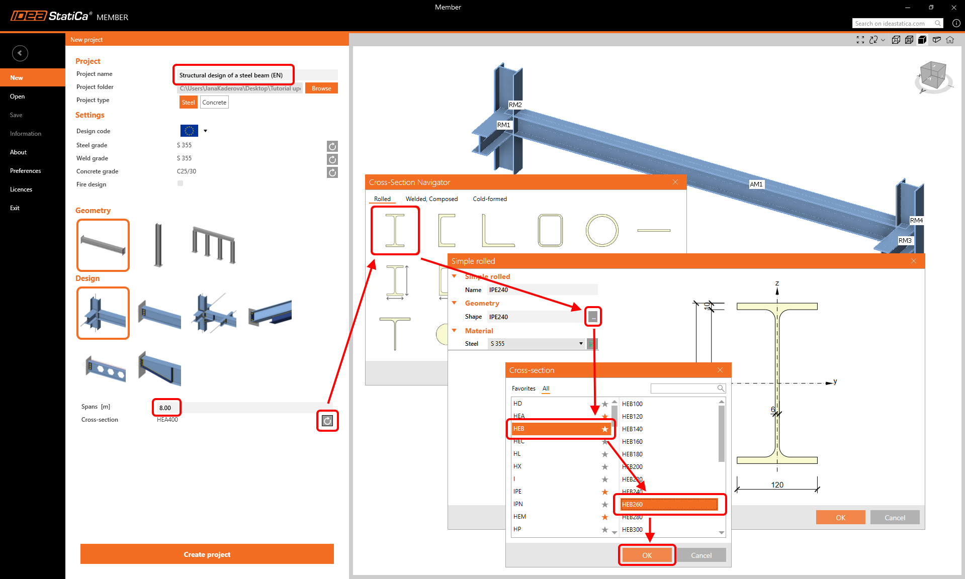
Créez un nouveau projet (barre latérale gauche) et saisissez le nom. Utilisez la géométrie de la poutre et le calcul avec les éléments associés. Définissez la portée à 8,0 m, sélectionnez la section transversale HEB 260 pour la poutre, et cliquez sur Créer le projet.
Élément analysé
Dans cet exemple, vous n'avez qu'un seul élément analysé - AM1, qui a été créé par le modèle.
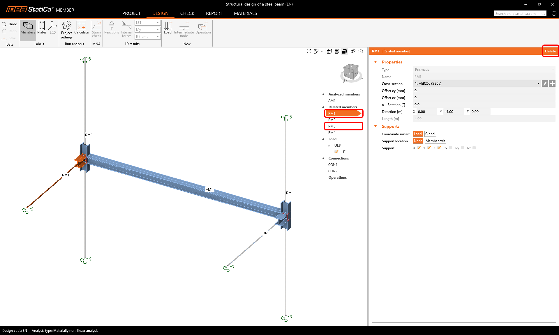
Éléments associés
Quatre éléments associés ont également été créés automatiquement. Cependant, nous n'avons besoin de conserver que les deux poteaux. Les deux autres poutres de contreventement peuvent être supprimées pour finaliser la disposition.
Sélectionnez et supprimez les éléments RM1 et RM3.
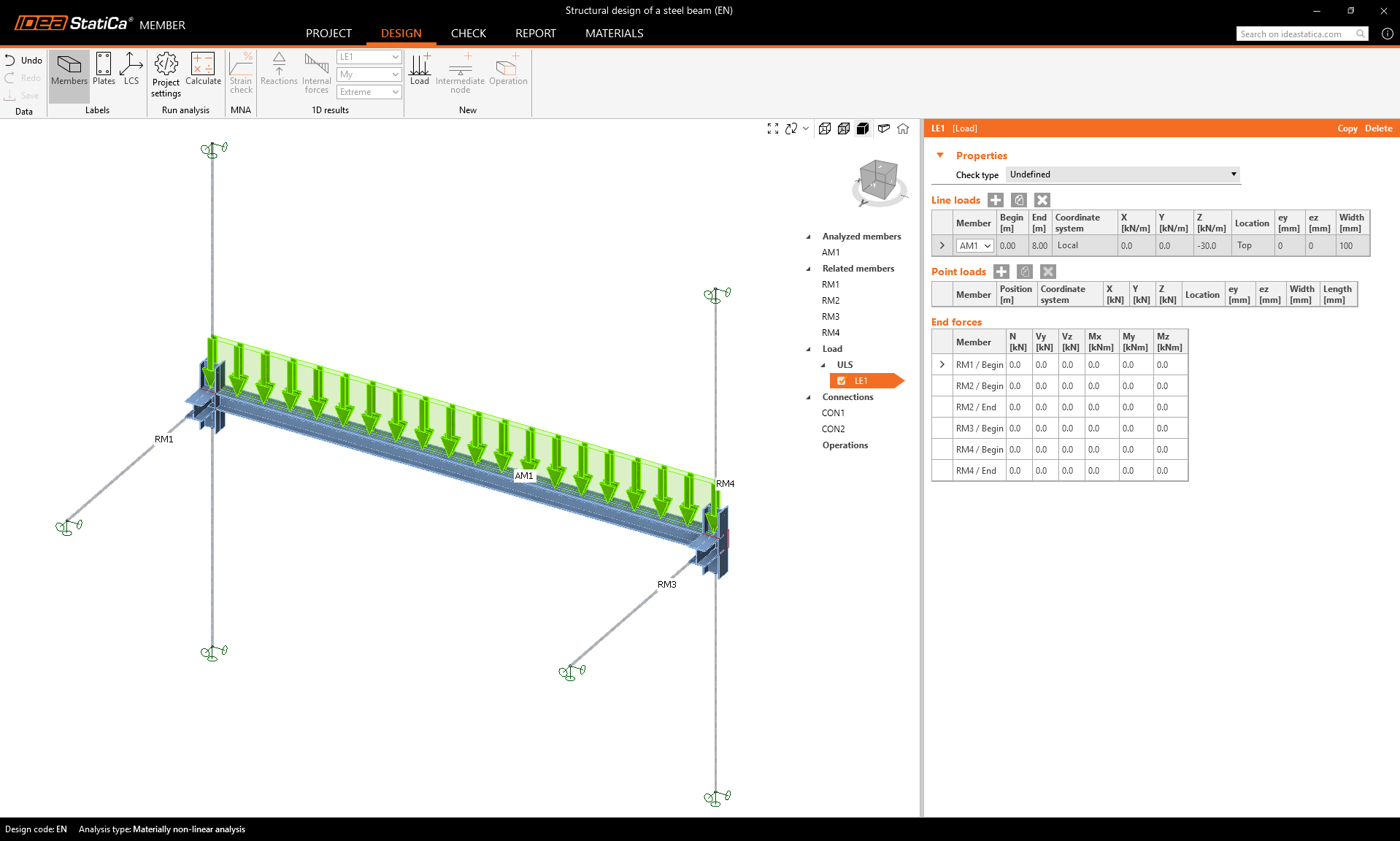
Charges
Définissez la charge permanente sur la poutre comme une charge linéaire et paramétrez ses valeurs.
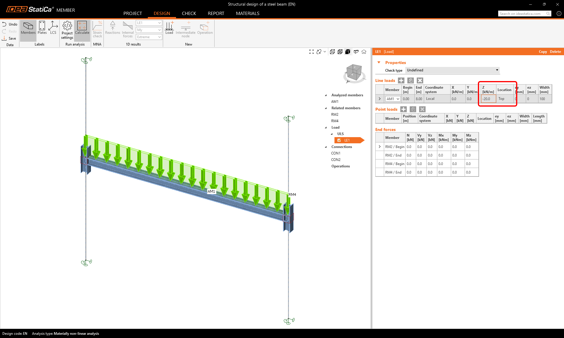
Modifiez la valeur de la charge ELU/LE1 à -20 kN/m dans la direction z agissant sur la semelle supérieure.
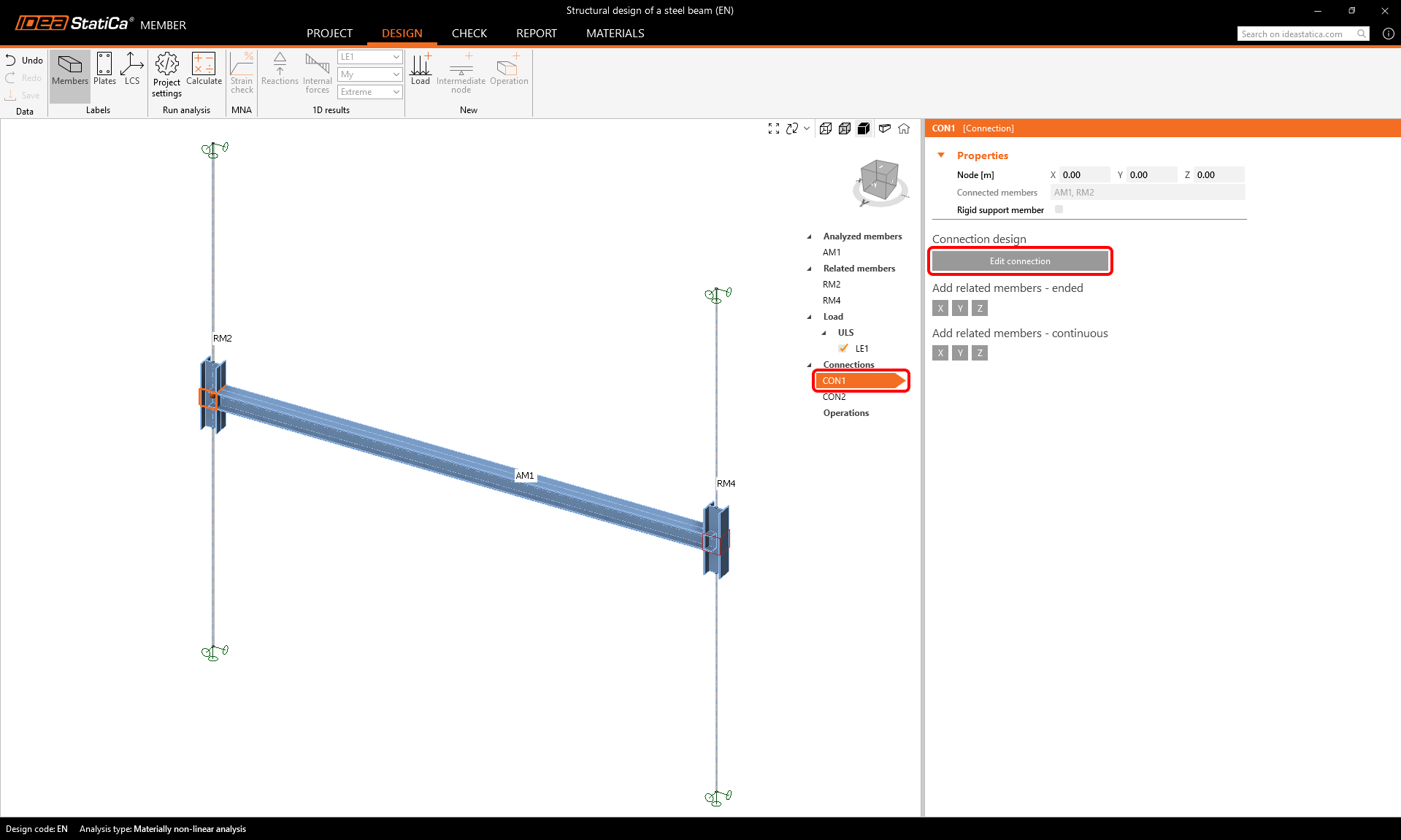
Assemblages
Pour définir les assemblages, sélectionnez l'élément CON1 puis cliquez sur Modifier l'assemblage.
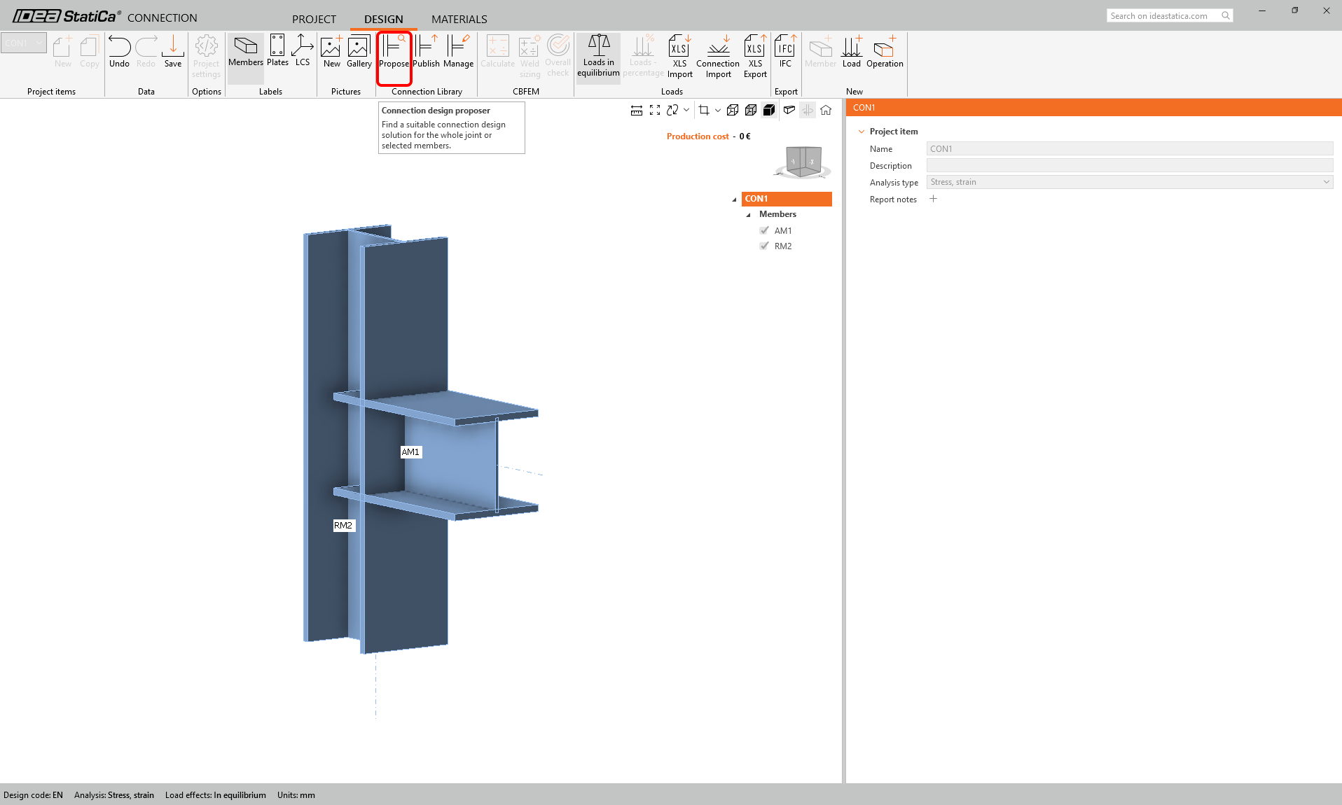
Il existe plusieurs façons de modéliser cet assemblage simple :
- En utilisant une opération de platine d'extrémité
- En utilisant un exemple de la Connection Library
Nous allons rechercher un modèle approprié dans la Connection Library - sélectionnez le bouton Proposer.
Faites défiler la bibliothèque et trouvez ce modèle :
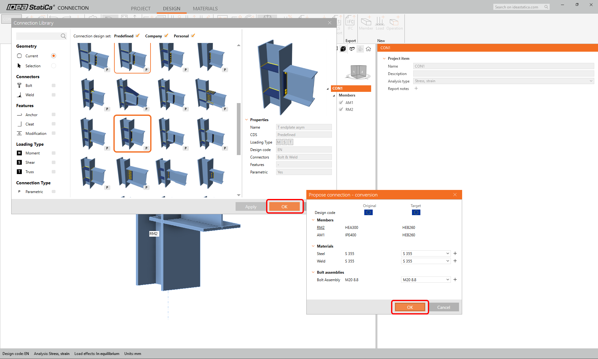
Modifiez les paramètres du modèle paramétrique : 2 rangées supérieures, 2 rangées inférieures, entraxe des colonnes de boulons 160 mm, première rangée, espacement des boulons et distance au bord - tous à 50 mm. Type et taille de boulon M16 8.8. Et décochez l'option raidisseur.
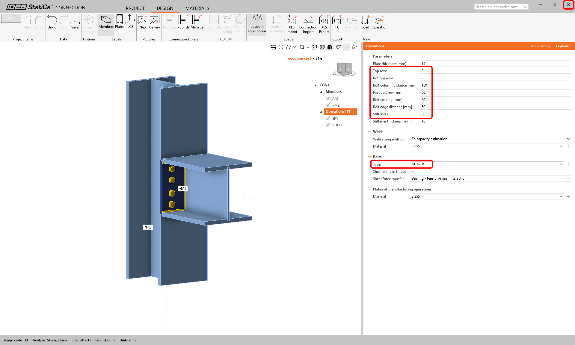
Enregistrez et fermez le calcul de l'assemblage et revenez au projet Member.
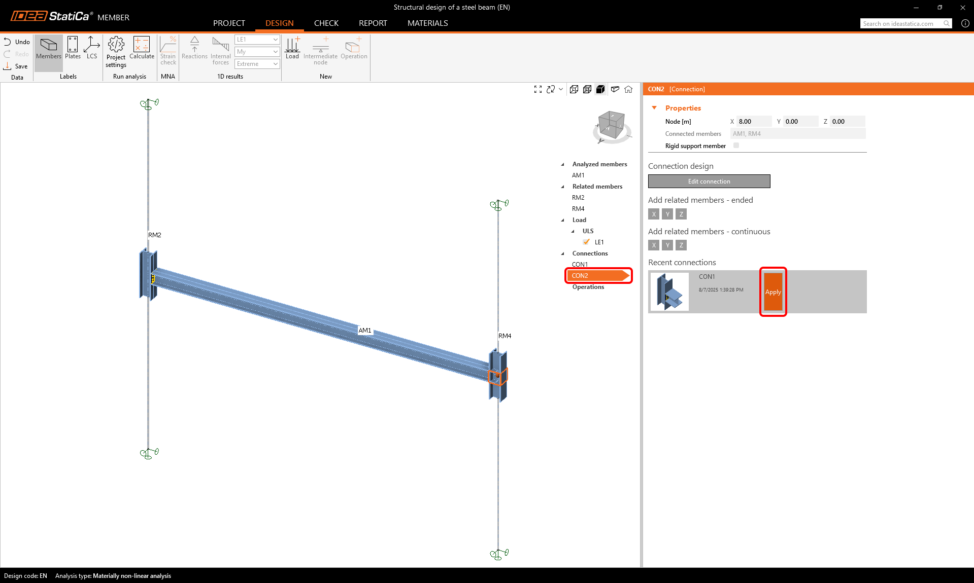
Pour calculer le second assemblage, sélectionnez l'assemblage CON2 et cliquez sur Appliquer pour copier le modèle proposé depuis l'assemblage CON1.
Vérification
Il existe trois types d'analyses qui se succèdent.
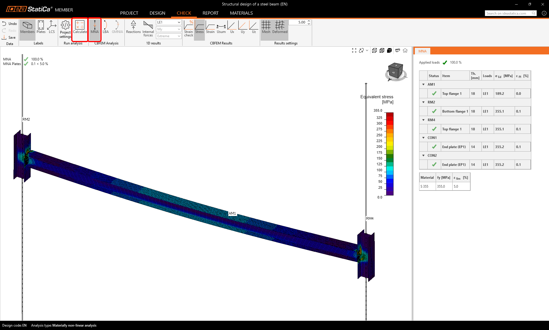
Commencez d'abord par l'Analyse non linéaire matérielle (MNA). Sélectionnez l'onglet Vérification, MNA, et cliquez sur Calculer.
Vous pouvez vérifier visuellement la distribution des contraintes sur la poutre en cliquant sur le bouton Contrainte dans le ruban supérieur et en sélectionnant Maillage, Déformé pour afficher la forme déformée.
La deuxième étape consiste à effectuer l'Analyse linéaire de flambement (LBA) et à cliquer sur Calculer.
Parcourez les différents modes de flambement dans les lignes du tableau LBA dans les résultats.
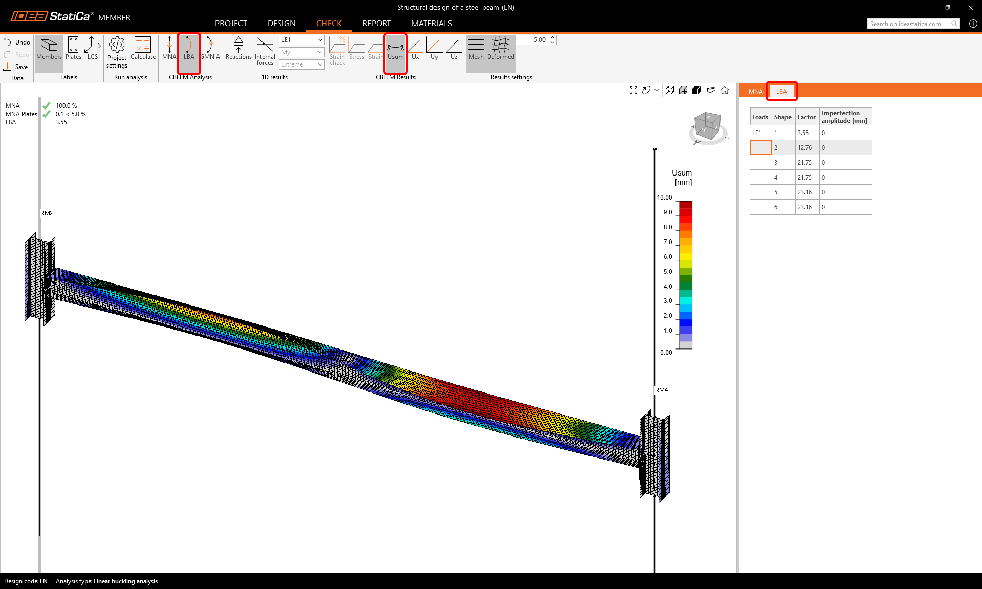
Comme vous pouvez le constater, les deux premiers facteurs de flambement sont inférieurs à 15, donc dans ce cas, une analyse géométriquement et matériellement non linéaire avec imperfections (GMNIA) doit être effectuée. Pour plus d'informations, veuillez consulter le fond théorique.
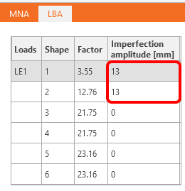
Pour la GMNIA, vous devez définir les imperfections (amplitudes des imperfections géométriques initiales).
Nous saisissons les valeurs 0,5 x L/300 = 0,5 x 8000 mm/300 = 13 mm.
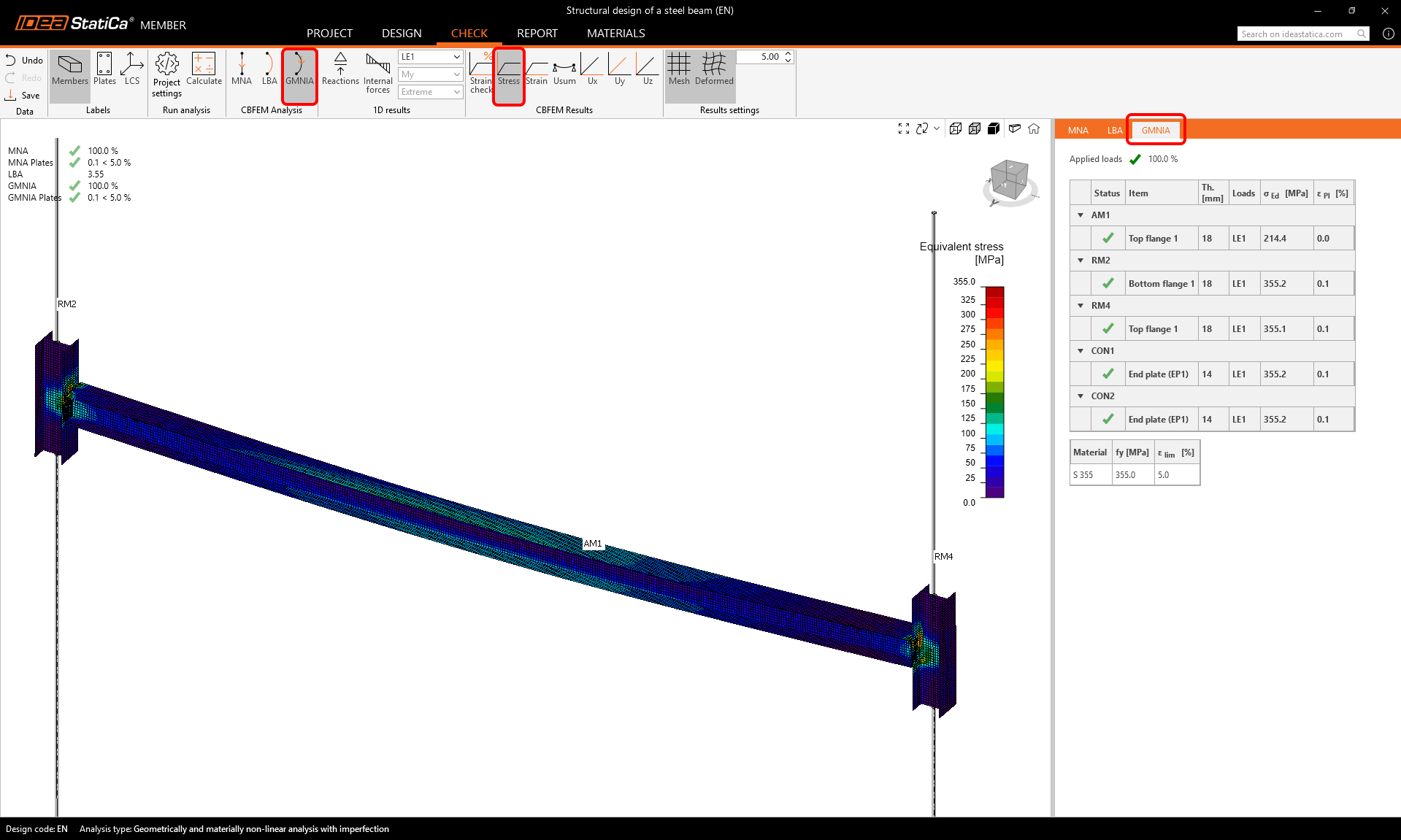
Lancez le calcul de l'Analyse géométriquement et matériellement non linéaire avec imperfections (GMNIA) en sélectionnant GMNIA et en cliquant sur Calculer.
Les résultats montrent que les dimensions de l'élément sont suffisantes même avec les imperfections initiales, et il satisfait aux vérifications normatives, en tenant compte également du risque de perte de stabilité.
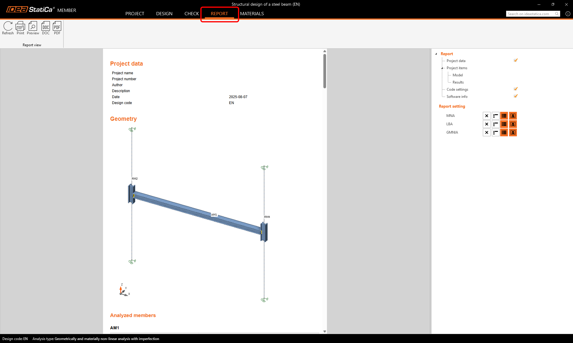
Rapport
Enfin, accédez à l'onglet Rapport. IDEA StatiCa propose un rapport personnalisable à imprimer ou à enregistrer dans un format modifiable.