
Shear wall with staggered openings
The primary function of shear walls is to resist lateral loads that occur during earthquakes, windstorms, or other dynamic events. By transferring the forces to the building's foundation, shear walls help to minimize structural damage and maintain the integrity of the structure. Shear walls are strategically placed within a building's floor plan to ensure the effective distribution of lateral loads. They are commonly located at the building's perimeter or near the building's core. In high-rise buildings, shear walls are often situated around the elevator and stairwell shafts to provide additional stiffness and stability. Shear walls offer several advantages, including increased structural stability, improved resistance to lateral loads, and enhanced overall safety during seismic events. Additionally, shear walls can contribute to architectural design by providing opportunities for creative expression while serving their structural function.
Model description
Four verification models have been established for evaluating results. Two of these models consider the characteristic material properties, while the other two are based on design values according to Eurocode 1992-1-1[3]. These verification models are based on the Compatible Stress Field Theory (CSFM)[1] and the Drucker-Prager Plasticity Model[2].
Please note the following provided model identification for better comprehension:
- Detail – Characteristic
- Detail – Design
- ABAQUS – Characteristic
- ABAQUS – Design
Geometry and materials
The testing model has been scaled down by a factor of four compared to the actual size. The foundation of the structure measures 1750 mm x 400 mm x 350 mm, while the walls have dimensions of 1250 mm x 2600 mm x 80 mm. The walls are divided into four levels with staggered openings, each measuring 250 mm x 500 mm. The concrete used is of C35/45 grade and is reinforced with B500B and a diameter of 6 mm. The loads are transferred using additional plates made of structural steel S235.
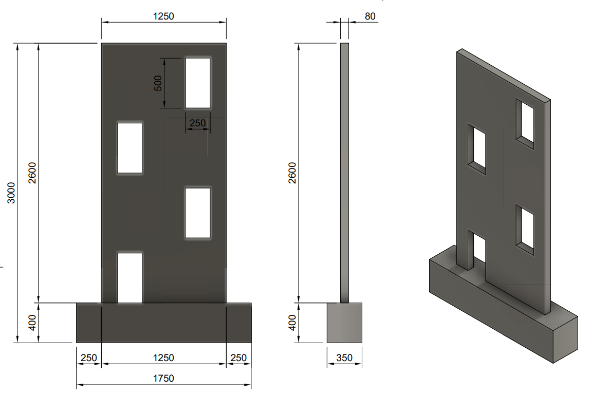
Fig. 1) Geometry
Compatible Stress Field Method
Assumptions
CSFM considers maximum principal concrete stress in compression (σc2r) and reinforcement stresses (σsr) at the cracks while neglecting the concrete tensile strength (σc1r = 0), except for its stiffening effect on the reinforcement. The consideration of tension stiffening allows the average reinforcement strains (εm) to be simulated. More information about the theory can be found in Theoretical Background.
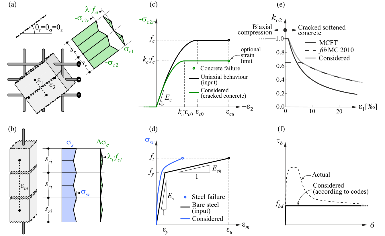
Fig. 2) Compatible Stress Field Method – Assumptions
Drucker-Prager Plasticity Model (DPPM)
Assumptions
Concrete Damage Plasticity (hereafter CDP) is based on the Drucker-Prager plasticity condition. This model is suitable for materials with internal friction, such as soil or concrete. The tensile strength is less than the compressive strength and the hydrostatic part of the stress tensor plays a role in the evolution of the plasticity surface. Under general stress, the plasticity condition has the surface of a rotating cone. The material model for compressive and tensile stresses also considers post-critical behavior, which is controlled by the so-called damage parameters, taking values from zero to one (for near-zero elastic stiffness of concrete in compression or tension in the post-critical condition). The larger the damage parameter number, the more the element is violated and does not contribute to the stiffness contribution.
The uniaxial material model in compression and tension for concrete is based on Thorenfeldt's theory[4]. All inputs are design values that follow the reliability approach of EN 1992-1-1[3]. The material model of reinforcement B500B is taken into consideration with tension stiffening. More information about theory.
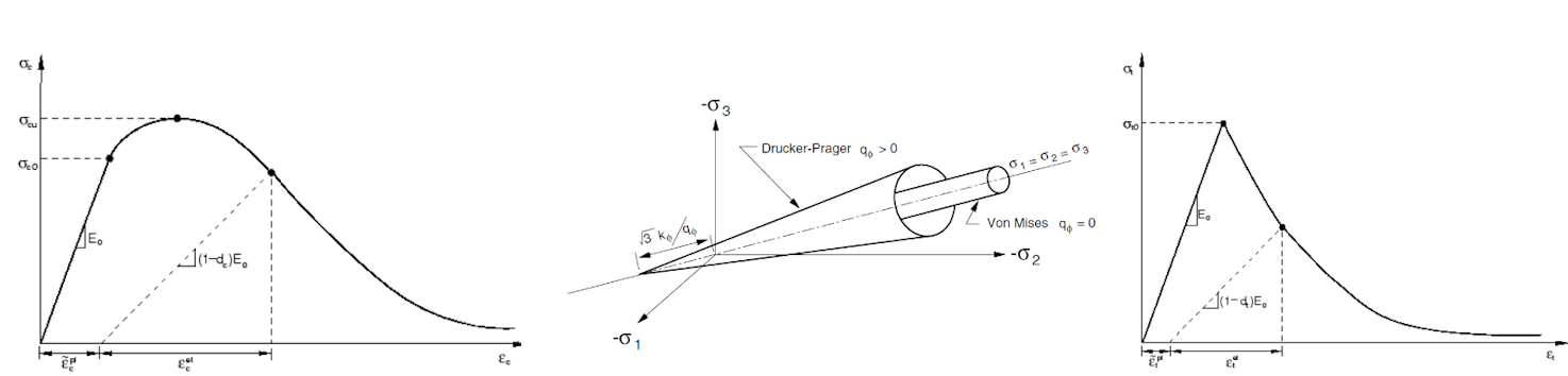
Fig. 3) Material model in compression (left), Drucker-Prager plasticity surface (middle), material model in tension (right)
Numerical models
Compatible Stress Field Method – IDEA StatiCa Detail
The numerical model is composed of 2D concrete planar elements and interconnected 1D reinforcement bars via MPC and bond elements to the concrete parts. The model incorporates two bearing devices in the form of steel plates. The top plate, measuring 350 x 80 x 20 mm, sustains a vertical load of 50 kN as the initial step of the loading process. The second plate, measuring 350 x 80 x 50 mm, is utilized as the second step for lateral loading in the wall plane, ensuring the uniform distribution of concentrated force during wall loading. The model is encastered, restraining the Tx, Tz, and Ry degrees of freedom, and assumes 2D plane stress conditions.
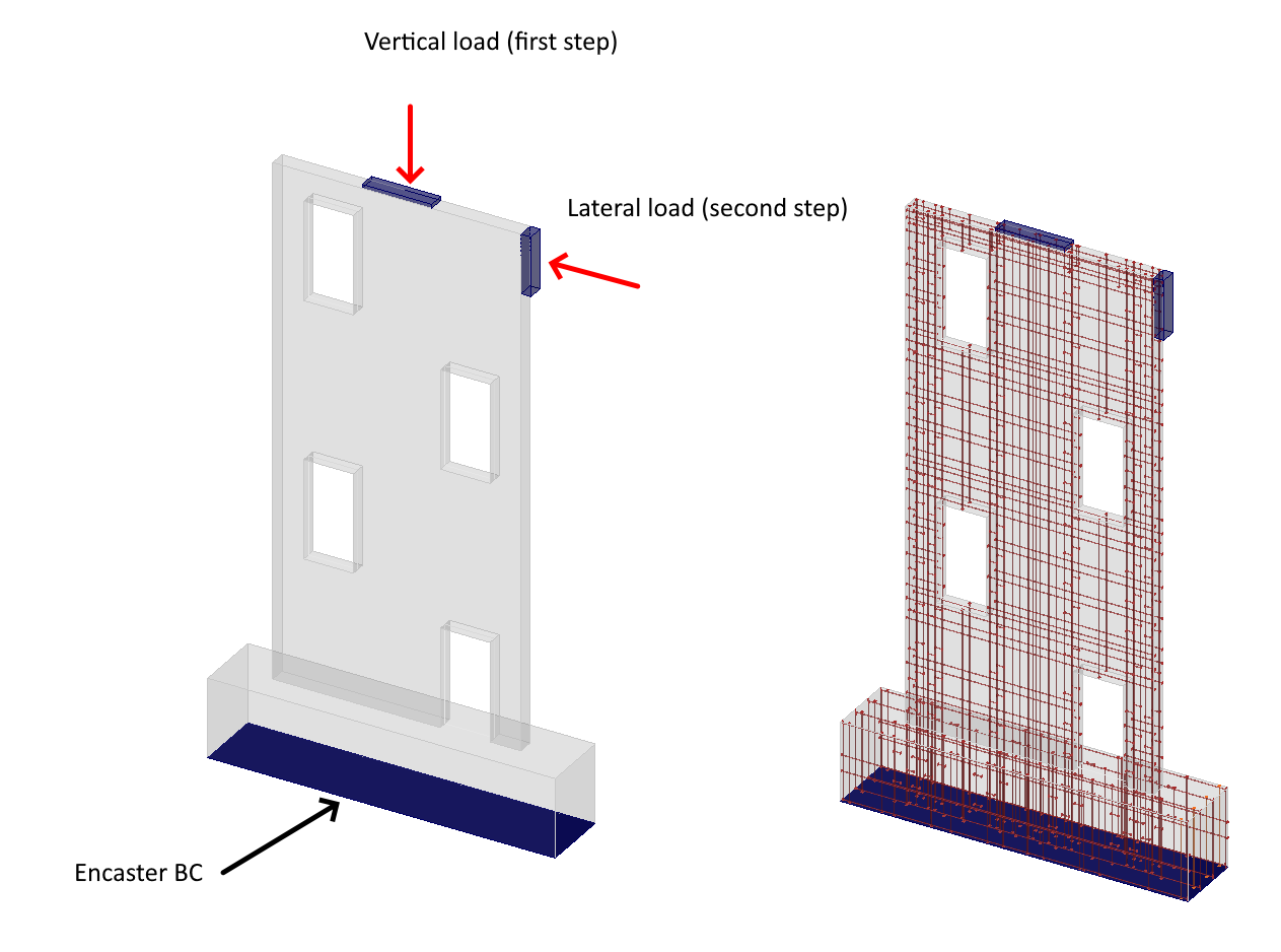
Fig. 4) Numerical model in IDEA StatiCa Detail (loading process)
Drucker-Prager Plasticity Model
The numerical model comprises 3D hexahedral elements reinforced with bars that are rigidly constrained within the host concrete region. The concrete and prestressing reinforcement consist of T3D2 elements transmitting solely axial effects. The occurrence of slip between concrete and reinforcement components is completely restrained by rigid constraints. The slip is simulated through tension softening in concrete, leading to element deletion upon reaching 70% damage in the post-critical state. This approach, to some extent, accounts for the cohesion model or dowel effect. The model attributes for model and plates align precisely with CSFM assumptions.
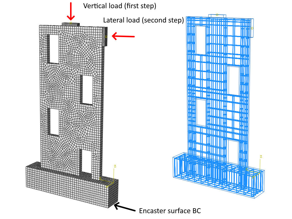
Fig. 5) Numerical model in ABAQUS (loading process)
Analysis
The loading process entails the incremental increase of deformations in the lateral directions as part of the monotonic loading process. Cyclic loading has not been taken into account in this analysis.
The numerical approaches vary slightly between the solutions from the point of view of the analysis. CSFM employs small deformation theory and incorporates material nonlinear analysis. In contrast, the Drucker-Prager and ABAQUS model employs geometrically and materially nonlinear analysis, providing a more precise solution when addressing large deformations.
Mesh Sensitivity
The sensitivity analysis provides insight into the discrepancies arising from discretization. The default configuration for CSFM involves a mesh multiplier of one, which adheres to the rule of incorporating a minimum of four elements on the smallest edge within the model. Subsequently, the entire model is meshed in accordance with this rule. The same strategy has been used for the model in ABAQUS.
Compatible Stress Field Method – IDEA StatiCa Detail
The data demonstrates that the average error between mesh multipliers of 0.5 and 2.0 is 7%. This lead to a low-sensitivity numerical approach.
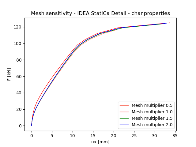
Fig. 6 Mesh sensitivity IDEA StatiCa Detail
Drucker-Prager Plasticity Model
The utilization of 3D hexahedral elements results in a nearly identical maximum force when employing a mesh multiplier of 1.0 and 2.0. The discrepancy in the maximum allowable force amounts to 1.3%, suggesting a mesh-insensitive solution. The model considers the dilatation angle of 30 degrees for analysis purposes.
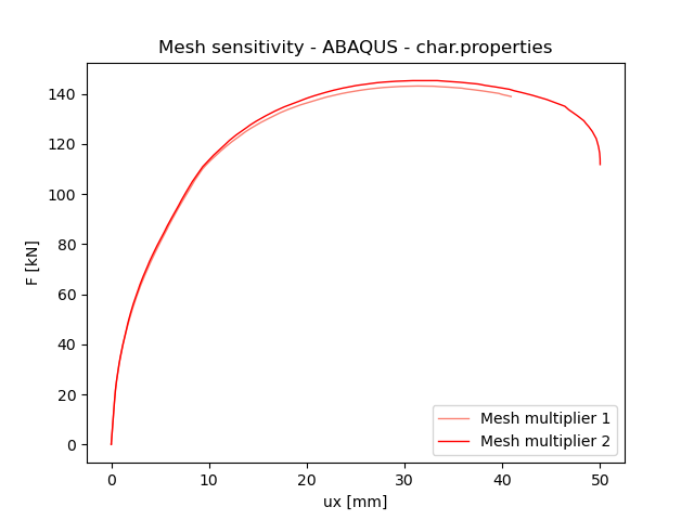
Fig. 7) Mesh sensitivity ABAQUS
Results
The following information should be noted: The provided values, such as principal stress in compression, deformations, maximum stress in compression and tension on the reinforcement bar, and the location of damage, are illustrated in the subsequent figures. All values are presented for a mesh multiplier of 1.0, which has been utilized as a verification parameter in CSFM[1] and is subsequently applied to the Drucker-Prager solution in ABAQUS[2]. The dilation angle used on the Drucker-Prager plasticity surface has been set at 30 degrees. The results will be presented for characteristic and design material properties that are evaluated based on the Eurocode 1992-1[3].
Principal stresses in compression
The primary distinction between the CSFM solution and the Drucker-Prager solution pertains to their treatment of stress. The Drucker-Prager solution incorporates confinement pressure, which has the capacity to significantly elevate the minimal principal stress under compression, thereby enabling the material to withstand high stress levels. Conversely, the CSFM solution determines the maximum characteristic or design uniaxial strength of the material, facilitating easy comparison with standard material libraries. The stress distributions across the solutions exhibit notable variations in regions where the confinement effect is pronounced.
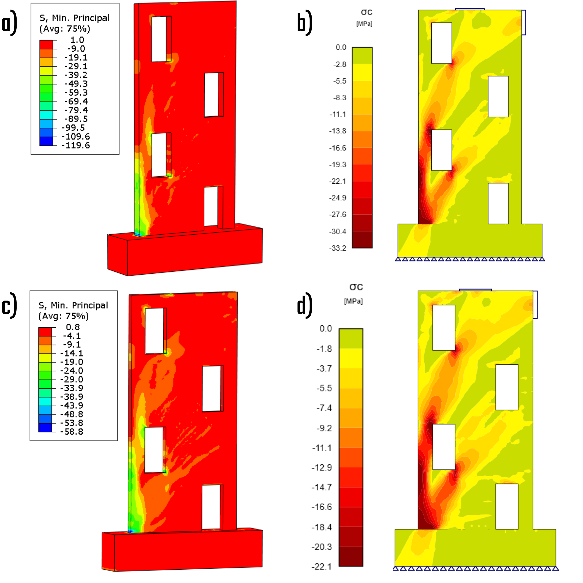
Fig. 8) a) Principal stress in compression – characteristic (ABAQUS); b) Principal stress in compression – characteristic (IDEA StatiCa); c) Principal stress in compression – design (ABAQUS); d) Principal stress in compression – design (IDEA StatiCa)
Stresses in reinforcements
The stress experienced by the reinforcement bars offers valuable information about the consistency of the results and the specific areas where high stresses are concentrated.
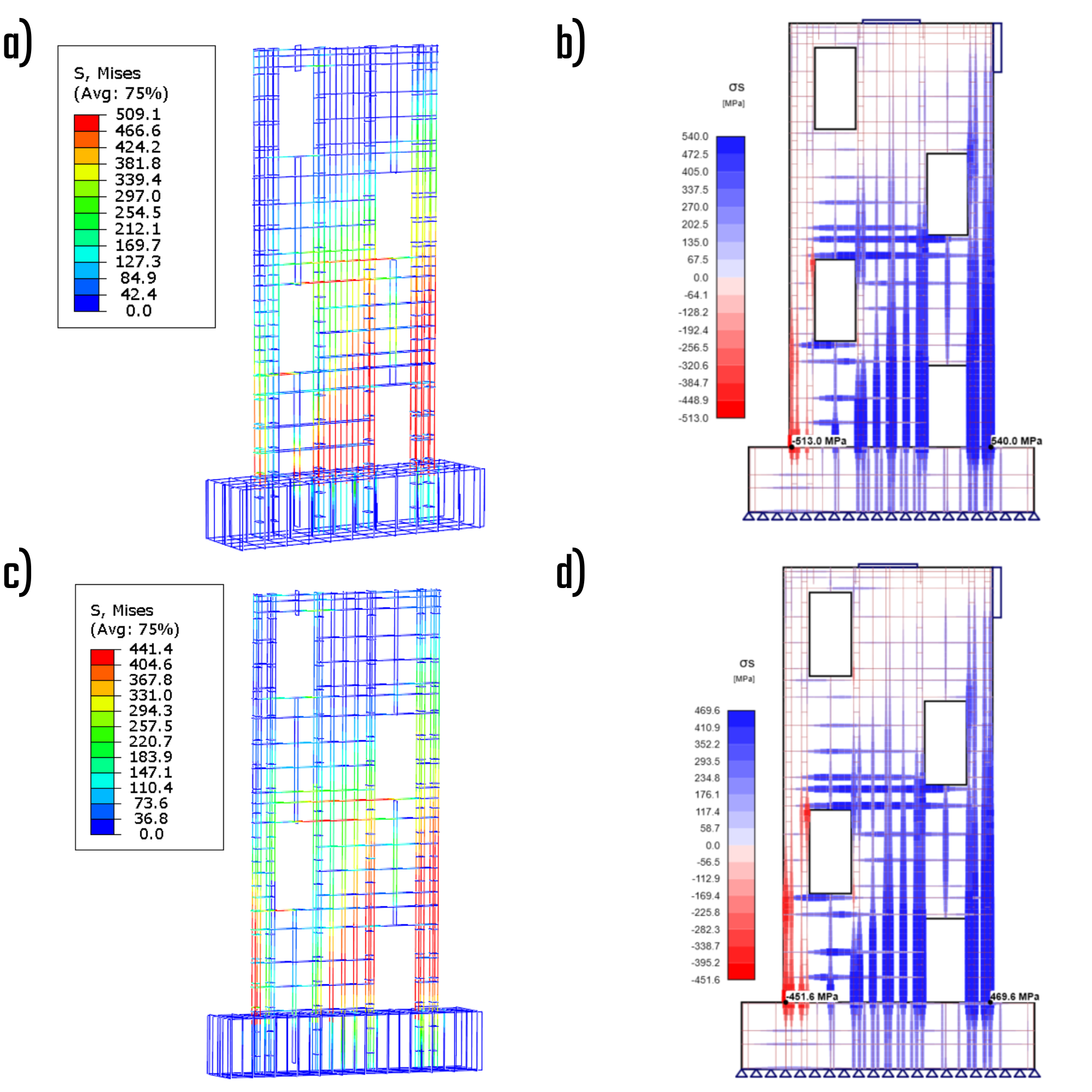
Fig. 9) a) Stress in bars – characteristic (ABAQUS); b) Stress in bars – characteristic (IDEA StatiCa); c) Stress in bars – design (ABAQUS); d) Stress in bars – design (IDEA StatiCa)
Deformations
The deformations serve as evidence that the geometrical nonlinearity has negligible implications, given the consistency ensured by the CSFM solution and material nonlinear analysis. This suggests that, for the specific wall specimen in question, the second-order effect will not exert an influence on the structural behavior.
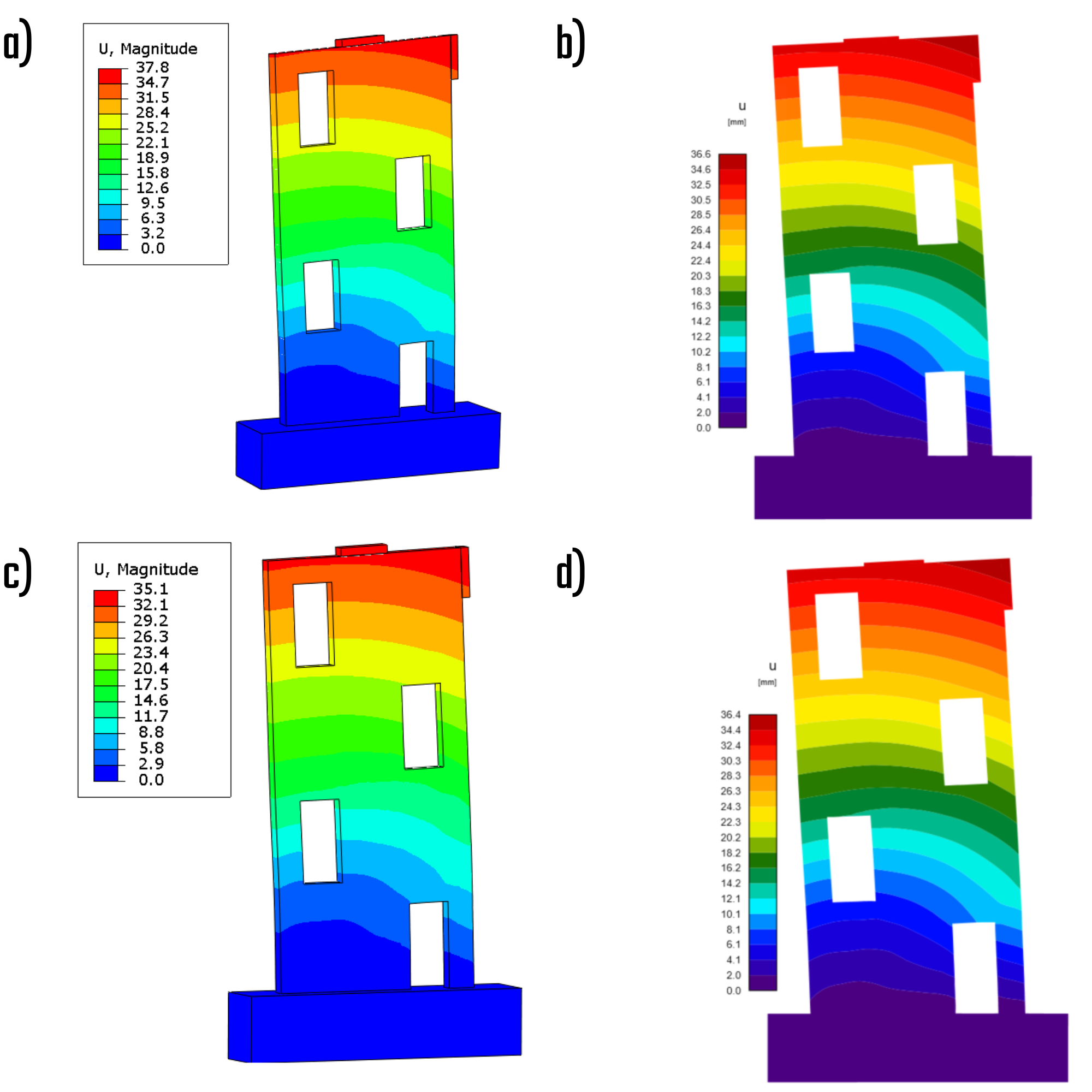
Fig. 10) a) Total deformations – characteristic (ABAQUS); b) Total deformations – characteristic (IDEA StatiCa); c) Total deformations – design (ABAQUS); d) Total deformations – design (IDEA StatiCa)
Force-deformations graph
The graphical representation effectively elucidates the intricate response of the wall to lateral load. The CSFM solution indicates a reduction in bearing capacity of approximately 16% for characteristic material properties and 7% for design material properties. These disparities stem from the incorporation of tension behavior in concrete within the Drucker-Prager Plasticity Model. The 16% and 7% deviations observed in the CSFM solution fall within an acceptable margin of safety.
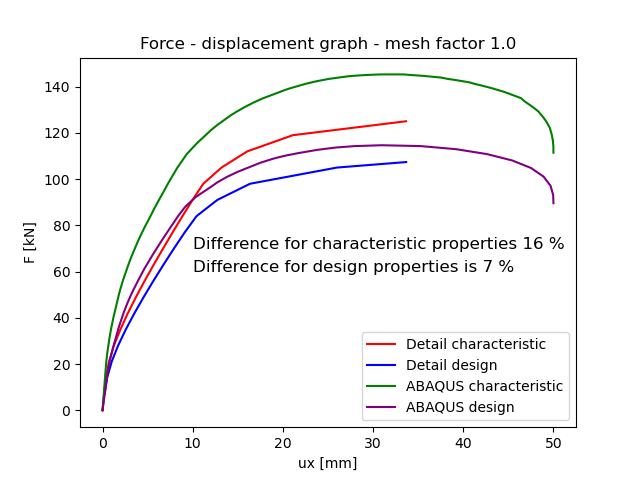
Fig. 11) Force deformation graph
Conclusion
The study emphasizes the critical role of shear walls in resisting lateral loads from dynamic events like earthquakes and windstorms, thereby ensuring structural stability and safety. Shear walls, strategically placed within building designs, help distribute lateral forces, particularly in high-rise structures, by often being located around elevator and stairwell shafts.
The analysis utilized four verification models based on both characteristic and design values according to Eurocode 1992-1-1, employing the Compatible Stress Field Method (CSFM)[1] and the Drucker-Prager Plasticity Model (DPPM)[2]. The study involved scaled-down models and detailed geometric and material specifications, with assumptions tailored for each analysis method.
CSFM focused on maximum principal concrete stress and reinforcement stresses, neglecting concrete tensile strength except for tension stiffening effects. In contrast, DPPM considered internal friction, tensile and compressive strengths, and post-critical behavior through damage parameters. Numerical models for both methods were created, with distinct approaches to loading and constraints.
Mesh sensitivity analysis indicated low sensitivity for both methods, with minor discrepancies observed in stress distributions and deformations. The results highlighted the differences in stress handling, particularly with confinement pressure in DPPM, and showed that geometrical nonlinearity had negligible effects on deformations.
Overall, the force-deformation graphs demonstrated the wall's response to lateral loads, with CSFM solutions indicating acceptable deviations from DPPM, affirming the robustness of both approaches in ensuring structural integrity under lateral forces.
References
[1] IDEA StatiCa. (n.d.). Theoretical background for IDEA StatiCa Detail. Retrieved May 30, 2024, from https://www.ideastatica.com/support-center/theoretical-background-for-idea-statica-detail
[2] Abaqus analysis user's manual. Abaqus analysis user's manual [online] www: https://classes.engineering.wustl.edu/2009/spring/mase5513/abaqus/docs/v6.6/books/usb/default.htm?startat=pt05ch18s05abm36.html
[3] EN 1992-1-1 Eurocode 2: Design of Concrete Structures—Part I: General Rules and Rules for Buildings. European Committee for Standardization, 2002.
[4] Massone, L. M.; et al. Shear-Flexure Interaction for Structural Walls, 2006. ResearchGate. https://www.researchgate.net/publication/284079633_Shear-flexure_interaction_for_structural_walls (accessed Jan 01, 2006).