3D CSFM defines the concrete behavior based on the Modified Mohr-Coulomb plasticity theory for monotonic loading. The method considers principal concrete stresses in compression and reinforcement stresses (σsr) at the cracks while neglecting the concrete tensile strength (tension cut-off), except for its stiffening effect on the reinforcement (Tension stiffening).
σc1r, σc2r, σc3r ≤ 0 MPa
The reinforcement bars are linked to concrete volume finite elements through bond elements, allowing for slip between the concrete and reinforcement. It should be noted that 3D CSFM is not suitable for simulating plain concrete due to the absence of tension, which may result in misleading deformation and model divergence. Generally, the Mohr-Coulomb theory includes two fundamental properties governing the evolution of the plasticity surface in compression and partially in tension: the internal friction angle φ and cohesion parameter c. 3D CSFM assumes a zero angle of internal friction (Fig. 1e), leading to a conservative design due to the plasticity surface resembling the Tresca model, which is independent of the first stress invariant.
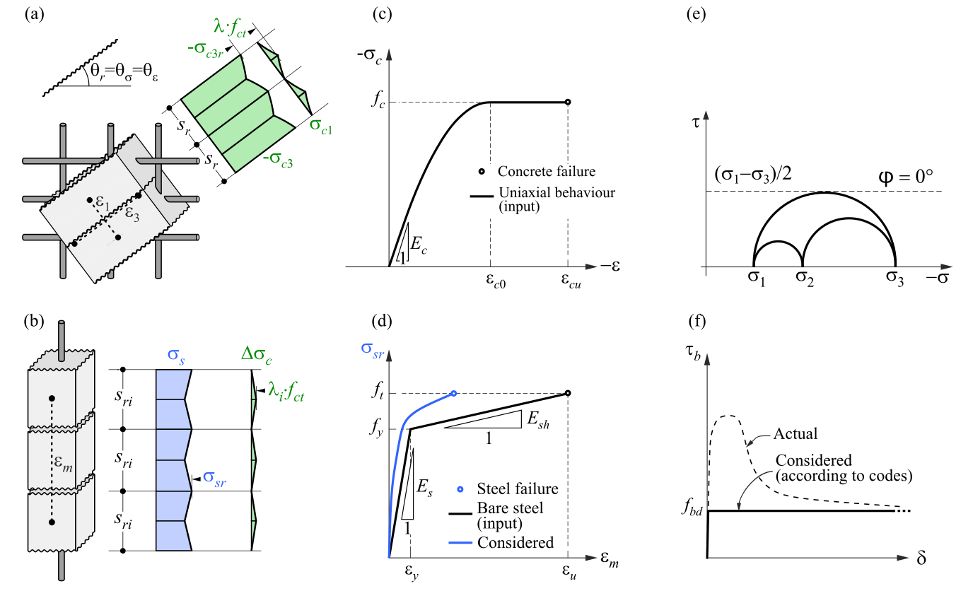
\( \textsf{\textit{\footnotesize{Fig. 1\qquad Basic assumptions of the 3D CSFM: (a) principal stresses in concrete; (b) stresses in the reinforcement direction;}}}\) \( \textsf{\textit{\footnotesize{(c) stress-strain diagram of concrete in terms of maximum stresses; (d) stress-strain diagram of reinforcement}}}\) \( \textsf{\textit{\footnotesize{in terms of stresses at cracks and average strains; (e) Mohr's circles for concrete model in 3D CSFM; (f) bond shear stress-slip}}}\) \( \textsf{\textit{\footnotesize{relationship for anchorage length verifications.}}}\)
Concrete
The presented material model is a multisurface plasticity model given by the combination of the Mohr-Coulomb and Rankine models for monotonic loading. It’s important to note that this model does not address unloading, therefore, state variables are not stored, as they would be in classical plasticity models used for cyclic loading.
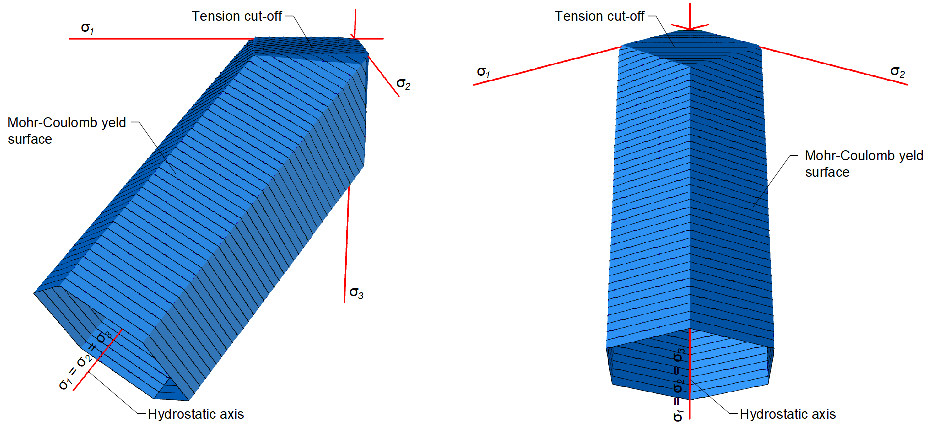
\[ \textsf{\textit{\footnotesize{Fig. 2\qquad Mohr-Coulomb multi-surface plasticity model for friction angle 0 degree}}}\]
As already mentioned, the material model is intended for use in applications that calculate the response of reinforced concrete (not suitable for plain concrete). This is due to the exclusion of concrete in tension. Therefore, the model is not even suitable for structural elements where the design rules for reinforced concrete such as minimum reinforcement ratio, maximum bar spacing, etc., are not fulfilled. It should also be added that, for numerical stability reasons, a very small tensile capacity is defined in the model. The tensile part is restricted by planes corresponding to the Rankine model.
3D CSFM in IDEA StatiCa Detail does not consider an explicit failure criterion in terms of strains for concrete in compression (i.e., it considers an infinitely plastic branch after the peak stress is reached). This simplification does not allow the deformation capacity of structures failing in compression to be verified. However, their ultimate capacity is properly predicted when the increase in the brittleness of concrete as its strength rises is considered by means of the 𝜂𝑓𝑐 reduction factor defined in fib Model Code 2010 as follows:
\[f_{c,red} = \eta _{fc} \cdot f_{c}\]
\[{\eta _{fc}} = {\left( {\frac{{30}}{{{f_{c}}}}} \right)^{\frac{1}{3}}} \le 1\]
where:
fc is the concrete cylinder characteristic strength (in MPa for the definition of \( \eta_{fc} \)).
The fc,red is then compared with the Equivalent Principal Stress σc,eq in concrete, which will be defined further, of course, with consideration of all safety factors prescribed by code.
A detailed description of the concrete model can be found at the following link:
Reinforcement
The bilinear stress-strain diagram for reinforcement bars, as defined by design codes (Fig. 1d), represents an idealized model. This model necessitates knowledge of the basic properties of the reinforcement during the design phase, specifically the strength and ductility class. Alternatively, users have the option to define a customized stress-strain relationship.
Tension stiffening is considered by modifying the stress-strain relationship of the bare reinforcing bar to capture the average stiffness of the bars embedded in the concrete (εm) (Fig 1b).
Anchorage
Bond-slip between reinforcement and concrete is introduced in the finite element model by considering the simplified rigid-perfectly plastic constitutive relationship presented in (Fig. 1f), with fbd being the design value (factored value) of the ultimate bond stress specified by the design code for the specific bond conditions.
This is a simplified model with the sole purpose of verifying bond prescriptions according to design codes (i.e., anchorage of reinforcement). The reduction of the anchorage length when using hooks, loops, and similar bar shapes can be considered by defining a certain capacity at the end of the reinforcement, as will be described further.
Anchors
The element of the anchor is defined as being able to transfer normal tensile or compression forces, as well as shear forces, considering the bending stiffness.
The following types of anchors are available:
- Cast-in-place anchors
- Reinforcement
- Washer plate
- Headed stud
- Cast-in-place reinforcement
- Reinforcement
- Threaded rods
Cast-in-place - Reinforcement
Modeled as ribbed reinforcement embedded in concrete. Bond strength is calculated according to selected code rules in the same way as for standard reinforcement. At the anchor end, an Anchorage type can be defined, working identically to reinforcement - an anchorage spring is applied with the β-factor set according to the chosen code. Three geometric shapes are available: Straight, L-shape, U-shape.
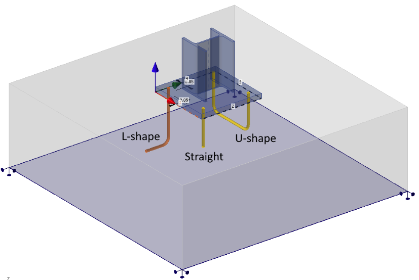
\[ \textsf{\textit{\footnotesize{Fig. 3\qquad Cast-in reinforcement anchor - shapes}}}\]
Cast-in-place - Washer plate and Headed stud
The washer plate and the head of the headed stud are modeled as a plate-shell element from the corresponding material attached directly to the anchor shank. It transfers load to the concrete through compression-only contact. Available shapes: circular and square (only circular for headed stud), with customizable dimensions. The washer plate and head model is elastic and is not checked for resistance.
At the finite element model level, the pull-out of the anchor is directly checked. The compression contact has stop criteria set so that it is not able to transfer greater contact stress to the concrete than prescribed by the selected standard. In practical terms, this means that if the anchor were to be loaded with a force that does not comply with the pull-out assessment, the result would be premature termination of the calculation because this stop criterion would be exceeded during further loading.
The anchor shank has zero bond strength – all load is transferred to the concrete through the plate or head into the concrete.
Post-installed - Reinforcement and Threaded rod
Designed as bars installed into drilled holes and bonded with adhesive. The engineer specifies the design bond strength directly from the technical specification of the adhesive product.
More information about connecting individual anchor types to the base plate or cast-in plate can be found in the chapter Finite elements types - Load transferring devices.