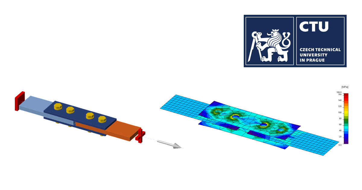
Fire design: Bolted lap joint
Analytical Model
The numerical model is verified by analytical model proposed by Eurocodes. EN 1993-1-8 provides design equations for calculating the shear resistance of a bolt per shear plane as follows:
\[F_{v,Rd}=\frac{\alpha_v f_{ub} A}{\gamma_{M2}}\]
where fub is the ultimate bolt material strengths, A is the nominal unthreaded or threaded body areas of the bolt and \(\alpha_v\) is a coefficient dependent on bolt class – for classes 4.6, 5.6 and 8.8 it is equal to 0.6, and for classes 4.8, 5.8, 6.8 and 10.9 it is equal to 0.5.
EN 1993-1-8 defines the bearing resistance per bolt as follows:
\[F_{b,Rd}=\frac{k_1 \alpha_b f_u dt}{\gamma_{M2}}\]
where d is the nominal bolt diameter, fu is nominal ultimate tensile strength of the plate, t is the thickness of connected material and \(\gamma_{M2}\) is the partial factor with the recommended value of 1.25. Parameters \(\alpha_b\) and k1 are determined considering mainly geometrical parameters as given below:
- perpendicular to the direction of load transfer for edge and inner bolts, respectively
\[k_1=\min \left ( 2.8\frac{e_2}{d_0} -1.7, \, 1.4 \frac{p_2}{d_0} -1.7, \, 2.5 \right )\]
\[k_1=\min \left ( 1.4 \frac{p_2}{d_0} -1.7, \, 2.5 \right )\]
- in the direction of load transfer
\[\alpha_b=\min \left ( \alpha_d, \, \frac{f_{ub}}{f_u}, \, 1.0 \right ) \]
\[ \alpha_d = \min \left ( \frac{e_1}{3d_0}, \, \frac{p_1}{3d_0}- 0.25 \right )\]
where d0 is the diameter of the bolt hole, fub is the ultimate strength of the bolt, fu is the ultimate strength of the plate, e1 is end distance, e2 is edge distance.
The fire design resistance of bolts loaded in shear should be determined from:
\[F_{v,t,Rd}=F_{v,Rd}k_{b,\theta} \frac{\gamma_{M2}}{\gamma_{M,fi}}\]
where \(k_{b,\theta}\) is the reduction factor determined for the appropriate bolt temperature from Table D.1; \(\gamma_{M,fi}\) is the partial factor for fire conditions.
The design bearing resistance of bolts in fire should be determined from:
\[F_{b,t,Rd} = F_{b,Rd} k_{b,\theta} \frac{\gamma_{M2}}{\gamma_{M,fi}} \]
Verification of resistance
Design resistances calculated by CBFEM were compared with the results of analytical model (AM). Results are summarized in Tab. 1. Steel grade was in all cases S355. The parameters are temperature, bolt material, splice thickness, bolt diameter and bolt distances.
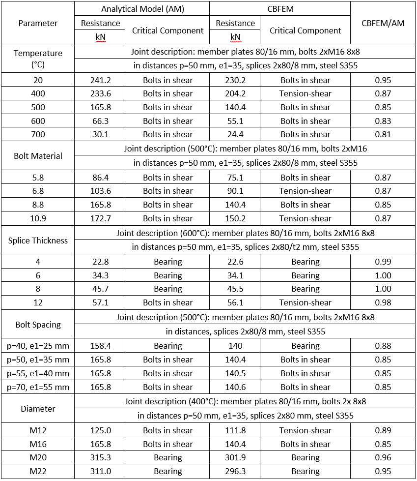
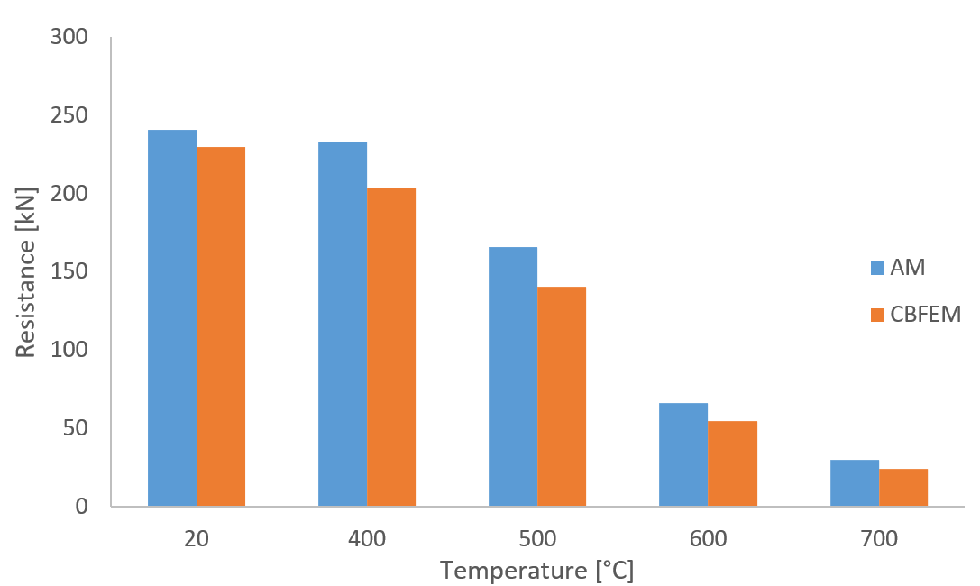
Fig. 1 Sensitivity study for temperature
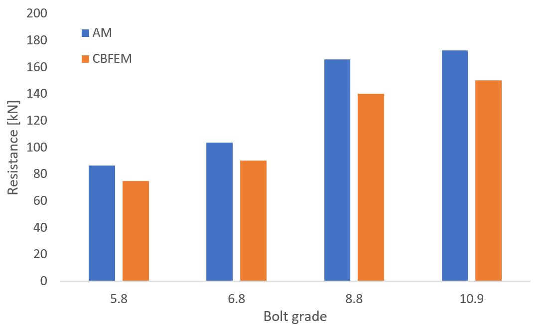
Fig. 2 Sensitivity study for the bolt grade (500 °C)
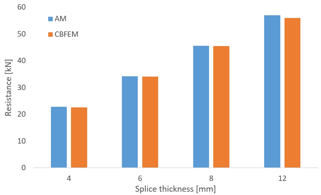
Fig. 3 Sensitivity study for the splice thickness (600 °C)
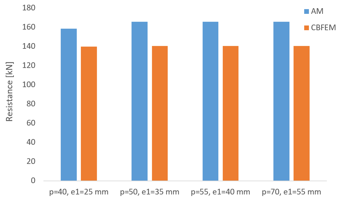
Fig. 4 Sensitivity study for the bolt spacing (500 °C)
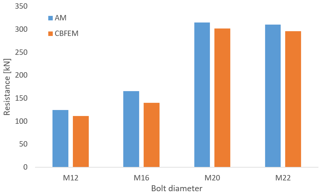
Fig. 5 Sensitivity study for the bolt size (400 °C)
Conclusion
IDEA StatiCa Connection provides the same or safer load resistances for all investigated cases of bolted lap joints at elevated temperatures. The reason is primarily the loading of bolts. Bolts in the analytical model are loaded purely by shear force, and any tensile forces due to plate deformations are neglected.
Benchmark example
Inputs
2xM16 8.8
Member plates 80/16 mm
Splices 2x80/8 mm
S355
Bolt distances p1 = 50 mm, e1 = 35 mm
Temperature 600°C
The model was created in IDEA StatiCa Connection application.
Outputs
The resistance of bolted lap joint at 600°C is 61 kN.
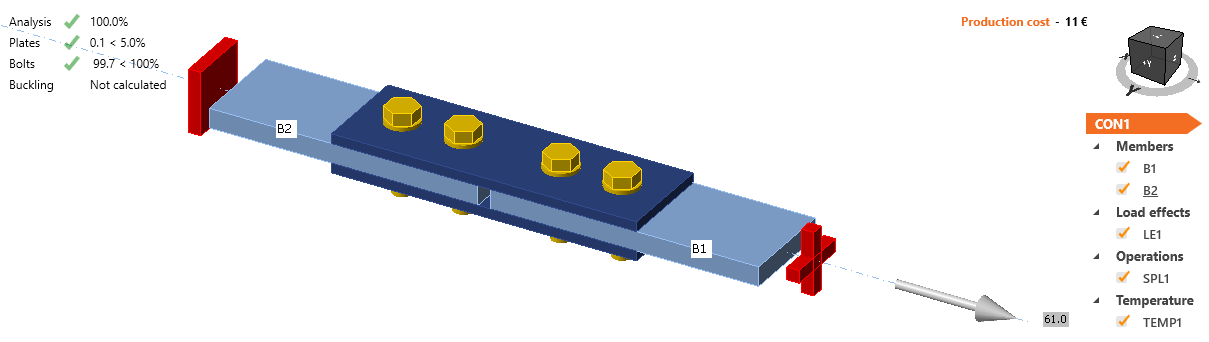
Fig. 6 Benchmark example of the bolted splices in shear
For other verification studies, visit our Support Center - Verifications.