Fire design: Welded lap joint
Description
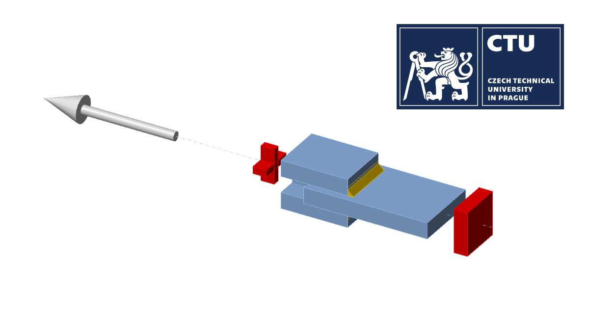
Three plates are connected in two configurations, namely with a transverse weld and with a longitudinal weld. The steel grade, length, and throat thickness of the weld are the variable parameters in the study. The joint is loaded by a normal force.
The model was created in IDEA StatiCa Connection application.
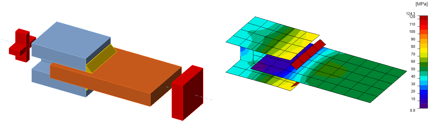
Fig. 1: Geometry of welded lap joint with transverse weld
Analytical Model
The design resistance per unit length of a fillet weld in fire should be determined from:
\[ F_{w,t,Rd}=F_{w,Rd}k_{w,\theta}\frac{\gamma_{M2}}{\gamma_{M,fi}}\]
where \(k_{w,\theta}\) is obtained from EN 1993-1-2, Table D.1 for the appropriate weld temperature; \(F_{w,Rd}\) is determined from EN 1993-1-8, Cl. 4.5.3.
Verification
Tab. 1: Transverse fillet welds
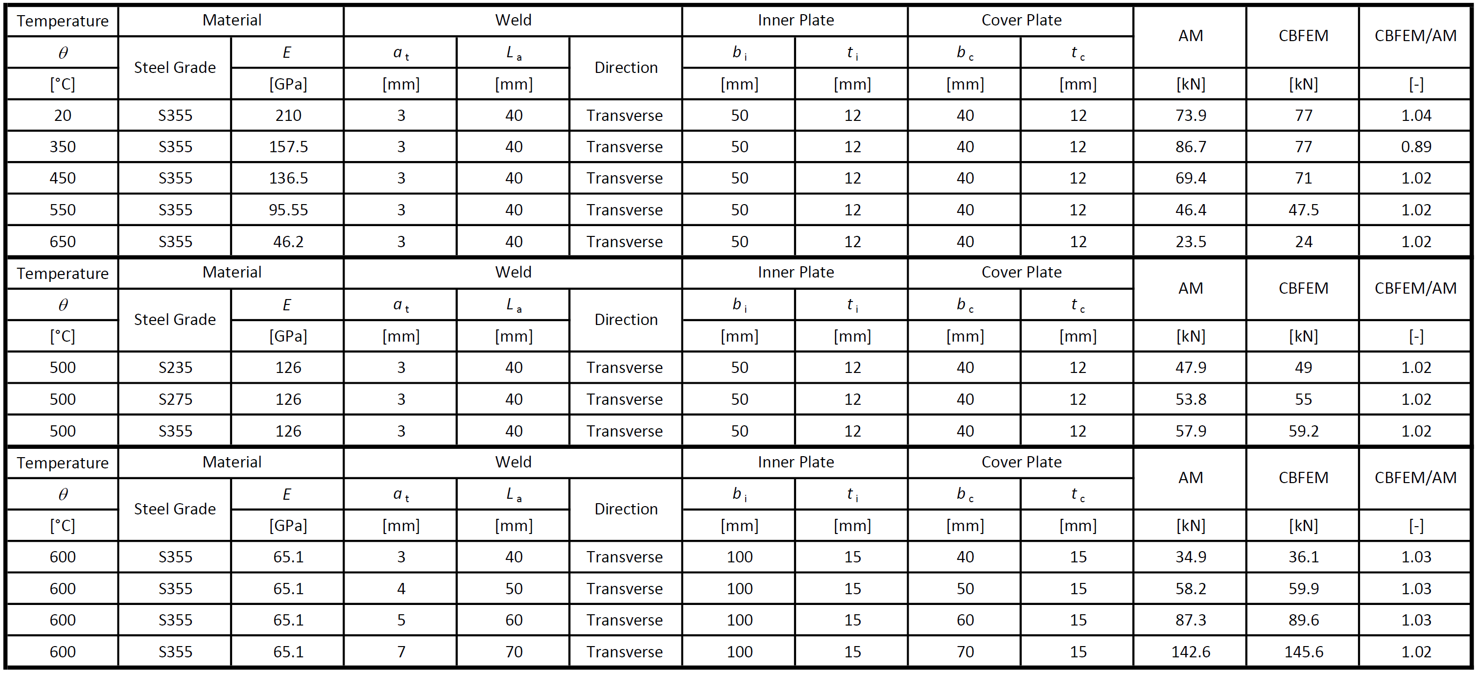
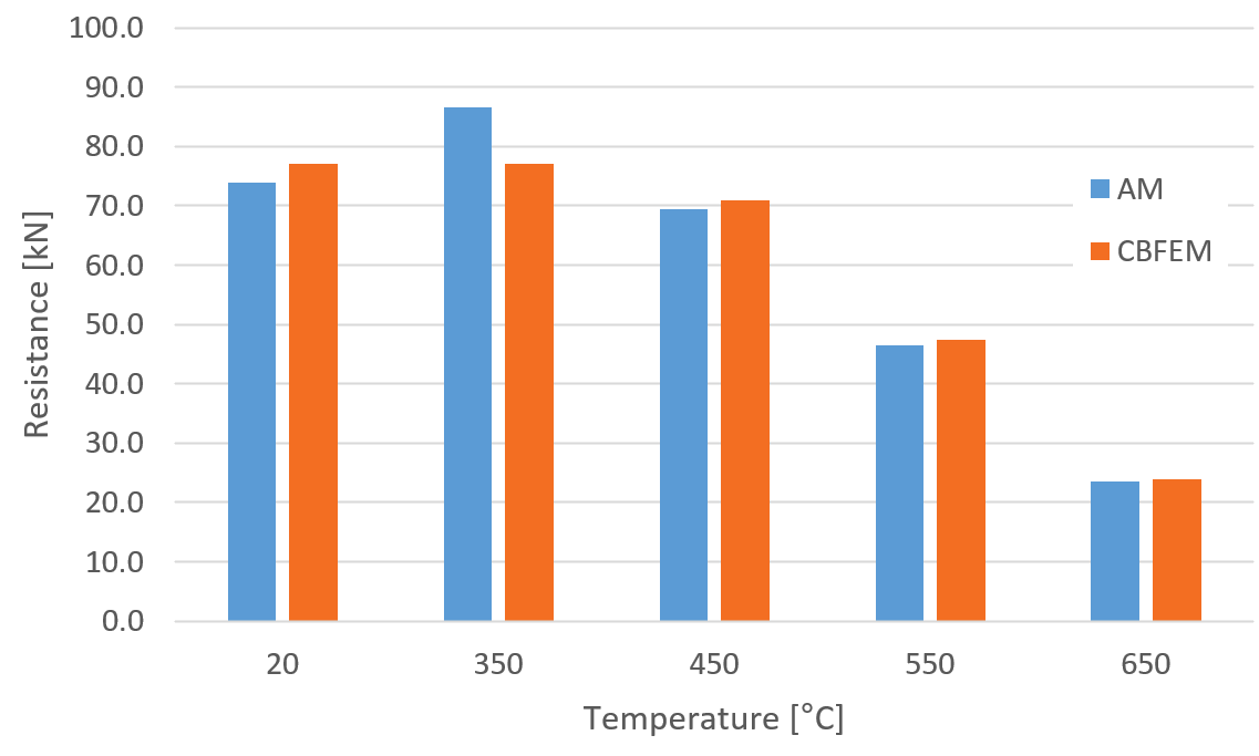
Fig. 2: Parametric study of temperature for transverse weld
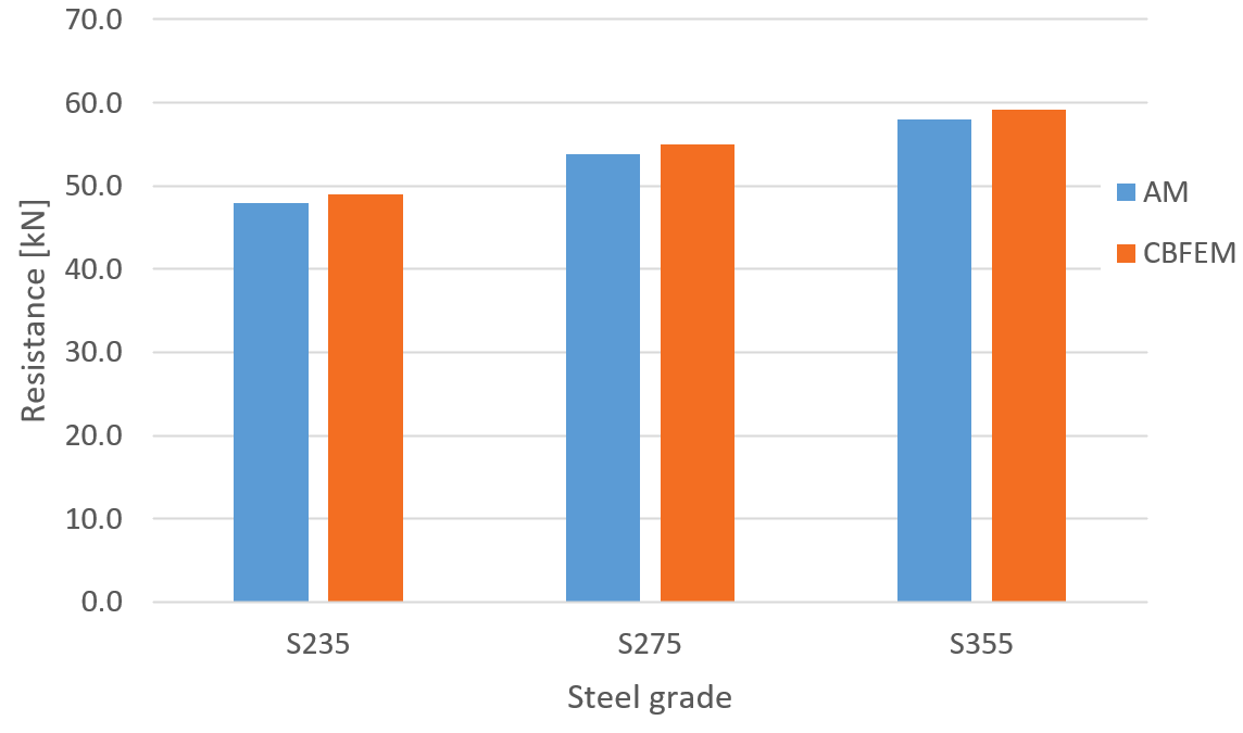
Fig. 3: Parametric study of steel grade for transverse weld
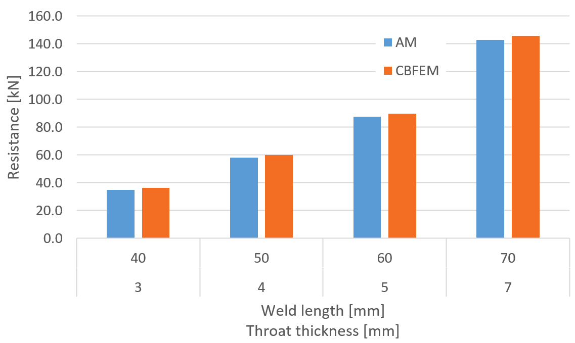
Fig. 4: Parametric study of weld length throat thickness for transverse weld
The resistance of transverse fillet welds is in most cases slightly higher (on average by 3 %) in CBFEM than in AM. The exception is the temperature of 350 °C. At this temperature, the resistance of welds is affected only slightly by fire, and the difference between partial safety factors \(\gamma_{M,fi}=1.0\) and \(\gamma_{M2}=1.25\) overweight the decrease due to fire. IDEA StatiCa does not allow the bolt or weld resistance to be higher in fire than at room temperature and assumes the minimum of:
- Load resistance multiplied by reduction factor for temperature, \(k_{\theta}\), and divided by safety factor for fire design situation, \(\gamma_{M,fi}\)
- Load resistance divided by safety factor for bolts and welds, \(\gamma_{M2}\)
Tab. 2: Longitudinal fillet welds
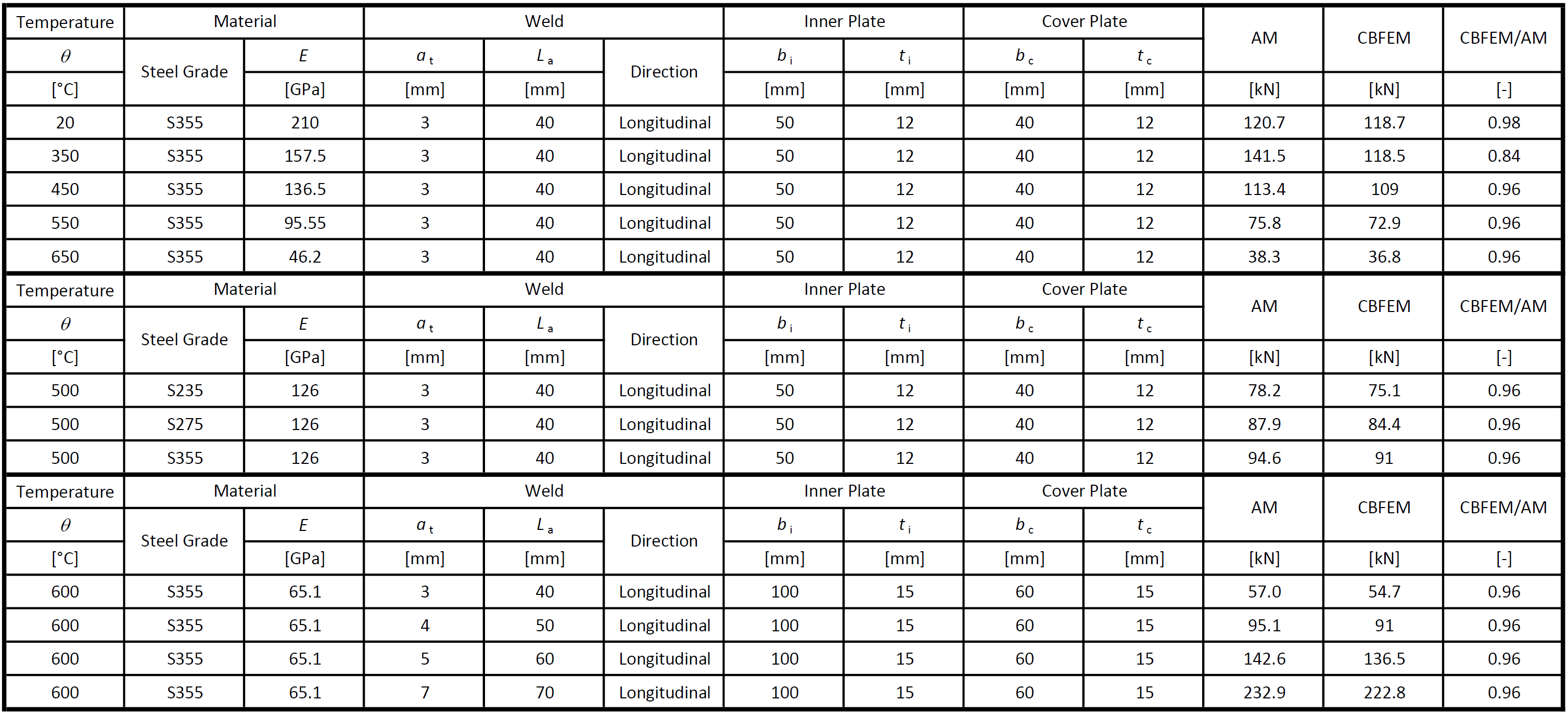
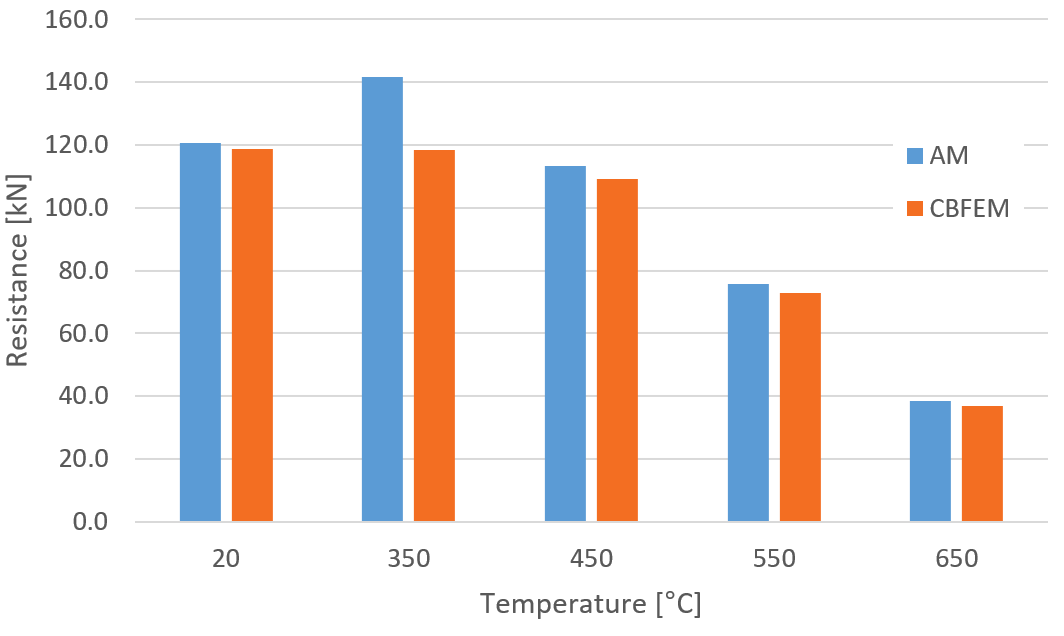
Fig. 5: Parametric study of temperature for longitudinal weld
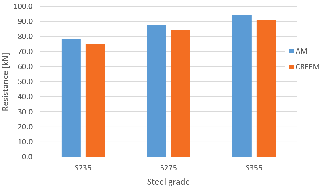
Fig. 6: Parametric study of steel grade for longitudinal weld
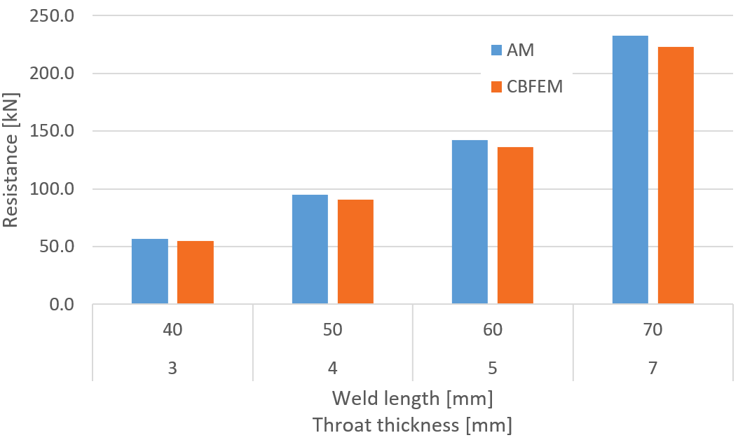
Fig. 7: Parametric study of weld length throat thickness for longitudinal weld
The resistance of longitudinal fillet welds is in most cases slightly lower (on average by 4 %) in CBFEM than in AM. The exception is the temperature of 350 °C for the same reason as for transverse welds.
Benchmark example
Inputs
Plate 2-3: Custom I-profile
- Thickness t2-3 = 12 mm
- Width b2-3 = 40 mm
- Steel S355
Plate 1
- Thickness t1 = 12 mm
- Width b1 = 50 mm
- Steel S355
- Model type N-Vy-Vz
Weld, transverse fillet welds
- Throat thickness ab = 3 mm
- Weld length Lb = 40 mm
Temperature: Both members
- \(\theta=550\,^\circ C\)
Output
- Design resistance in tension FRd = 48 kN
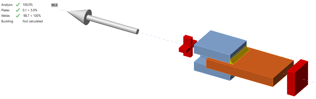
Fig. 8: Benchmark example for the welded lap joint
For other verification studies, visit our Support Center - Verifications.