End plate minor axis connection
Description
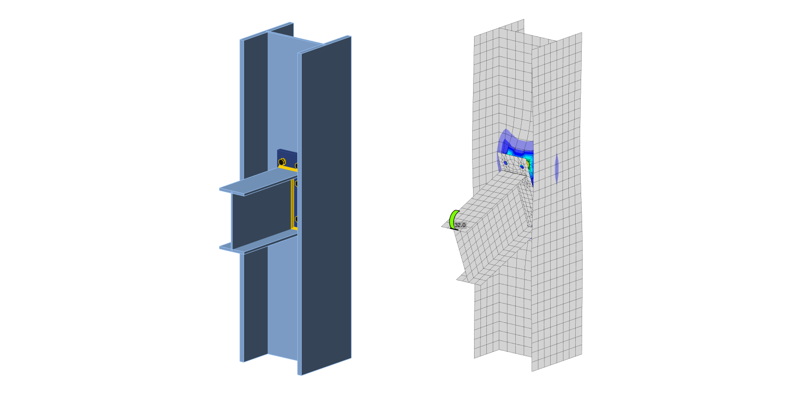
Component-based finite element method (CBFEM) model of the beam to column joint is verified on Component method (CM). The extended end plate with three bolt rows is connected to column web and loaded by bending moment; see Fig. 5.3.1.

\[ \textsf{\textit{\footnotesize{Fig. 5.3.1 Joint geometry - all dimensions in mm}}}\]
Analytical model
Three components, which are guiding the behavior, are the end plate in bending, the beam flange in tension and in compression, and the column web in bending. The end plate and the beam flange in tension and in compression are designed according to EN 1993-1-8:2005. The behavior of the column web in bending is predicted according to (Steenhuis et al. 1998). The results of experiments of the beam to column minor axis joints, e.g. (Lima et al. 2009), show good prediction of this type of joint loaded in-plane of a connected beam.
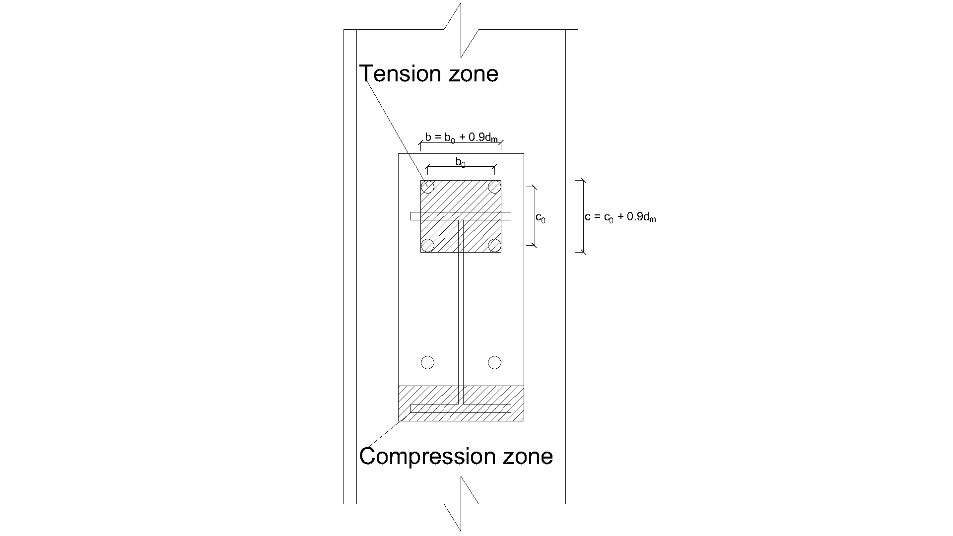
\[ \textsf{\textit{\footnotesize{Fig. 5.3.2 Definition of the tension zone}}}\]
\[F_\mathrm{{local.Rd }}=\min \left(F_\mathrm{{punch.Rd }} ; F_\mathrm{{comb.Rd }}\right)\]
\[F_\mathrm{ {punch.Rd }} = n \cdot \pi\cdot d_\mathrm{m} \cdot t_\mathrm{w c} \cdot f_\mathrm{y} /\left(\sqrt{3} \cdot \gamma_\mathrm{M 0}\right) \quad \text{bolted end plate }\]
\[b = b_0 + 0.9 \cdot d_\mathrm{m}\]
\[c = c_0 + 0.9 \cdot d_\mathrm{m}\]
\[a = L - b\]
\[k= 1 \quad \text{ if }\quad(b+c) / L>0.5\]
\[k=0.7+0.6(b+c) / L \quad \text{ if }\quad(b+c) / L \leq 0.5\]
\[b_\mathrm{m}=L\left[1-0.82 \frac{t_\mathrm{w c}^2}{c^2}\left(1+\sqrt{1+2.8 \frac{c^2}{t_\mathrm{w c} L}}\right)^2\right], \quad \text{ but } \quad b_\mathrm{m} \geq 0\]
\[x_0=L\cdot\left[\left(\frac{t_\mathrm{w c}}{L}\right)^{\frac{2}{3}}+0.23 \frac{c}{L}\left(\frac{t_\mathrm{w c}}{L}\right)^{\frac{1}{3}}\right] \cdot\left(\frac{b-b_\mathrm{m}}{L-b_\mathrm{m}}\right)\]
\[x = 0 \quad b \leq b_\mathrm{m}\]
\[x=-a+\sqrt{a^2-1.5 a c+\frac{\sqrt{3}}{2} t_\mathrm{w c}\left[\pi \sqrt{L\left(a+x_0\right)}+4 c\right]} \quad \text{ if }\quad b>b_\mathrm{m}\]
\[F_\mathrm{c o m b . R d}=k\cdot t_\mathrm{w c}^2 \cdot f_\mathrm{y}\left[\frac{\pi \sqrt{L(a+x)}+2 c}{a+x}+\frac{1.5 c x+x^2}{\sqrt{3} t_\mathrm{w c}(a+x)}\right] / \gamma_\mathrm{M 0}\]
\[\rho = 1 \quad \text{ if }\quad z / (L-b) \leq 1\]
\[\rho = z / (L-b) \quad \text{ if }\quad 1<z / (L-b) \leq 10\]
\[F_\mathrm{g l o b a l . R d}=\frac{F_\mathrm{c o m b . R d}}{2}+\frac{t_\mathrm{w c}^2 f_\mathrm{y}}{4}\left(\frac{2 b}{z}+\pi+2 \rho\right) / \gamma_\mathrm{M 0}\]
\[F_\mathrm{Rd} = \min \left(F_\mathrm{{local.Rd }} ; F_\mathrm{g l o b a l . R d}\right)\]
\[M_\mathrm{Rd} = z \cdot F_\mathrm{Rd}\]
Where:
- \(t_\mathrm{w c} \quad\) is the thickness of the column web
- \(f_\mathrm{y} \quad\) is the yield strength of the column web
- \(\gamma_{\mathrm{M} 0}\) is the partial safety factor of steel
- \(\gamma_{\mathrm{M} 0}\) is the partial safety factor of steel
- \(n\) number bolt rows in tension
- \(d_\mathrm{m}\) bolt head diagonal diameter
- \(b_0\) horizontal distance between bolts
- \(c_0\) vertical distance between bolts
- \(z\) lever arm of the joint
- \(F_\mathrm{ {punch.Rd }} \quad\) is the resistance to punching shear
- \(F_\mathrm{ {comb.Rd }} \quad\) is the resistance to combined punching, shear and bending
Numerical model
Assessment is based on the maximum strain given according to EN 1993-1-5:2006 by the value of 5 %. Detailed information about CBFEM model is summarized in Chapter 3.
Verification of resistance
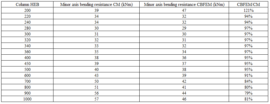
The sensitivity study of the joint resistance was prepared for column cross-sections. Joint geometry is shown in Fig. 5.3.1. In Tab. 5.3.1 and in Fig. 5.3.3, the results of calculations in case of enlarging end plate P18 relatively with the column section are summarized.
Tab. 5.3.1 Results of prediction of the of end plate minor axis connection for different rafters
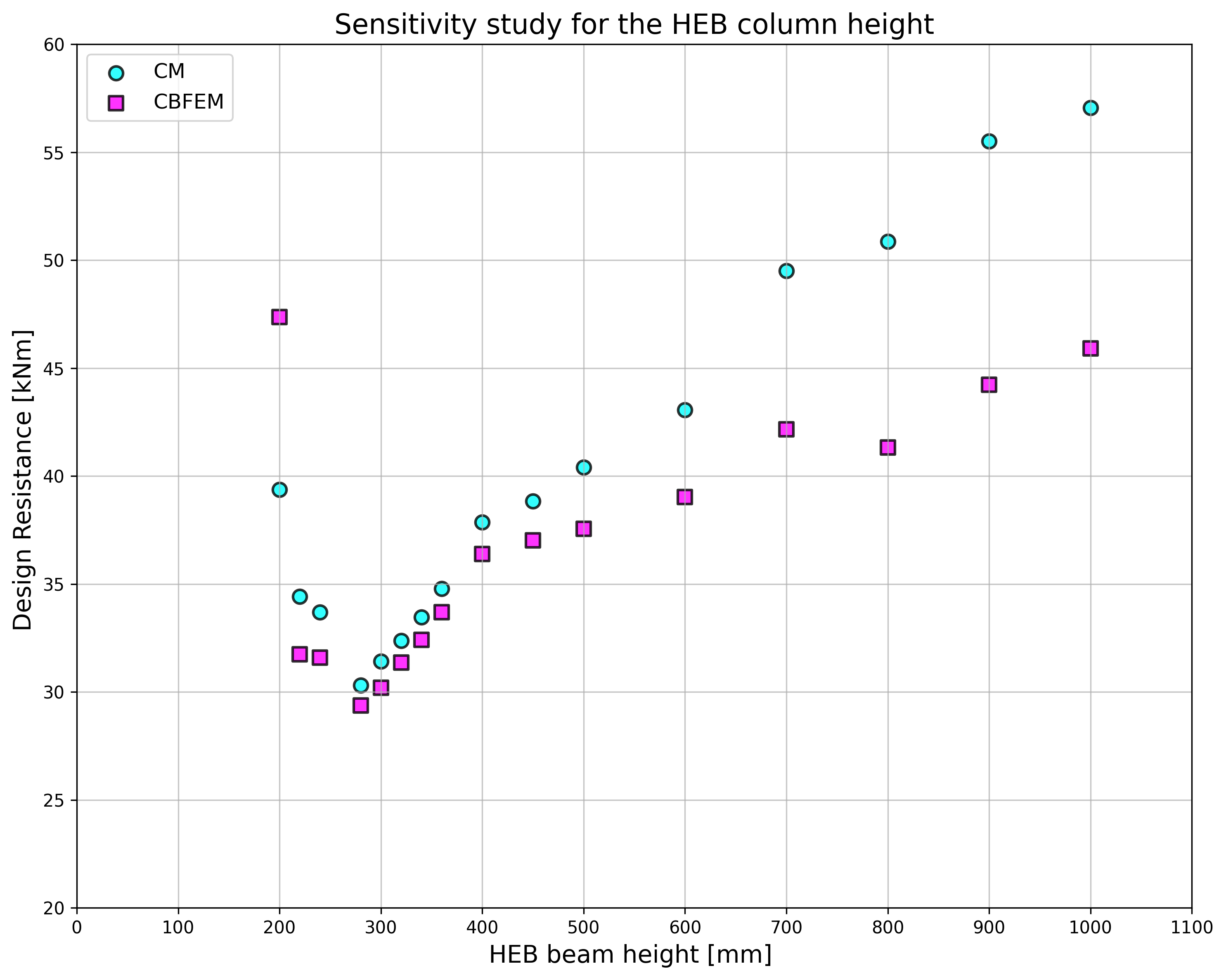
\[ \textsf{\textit{\footnotesize{Fig. 5.3.3 Comparison resistance of end plate minor axis connection predicted by CBFEM and CM}}}\]
Global behavior
Global behavior is presented on force-deformation curve. Beam IPE 240 is connected to column HEB 300 with six bolts M16 8.8. End plate geometry is shown in Fig. 5.3.1 and in Tab. 5.3.1. Comparison of both methods results is presented in Fig. 5.3.4 and in Tab.5.3.2. Both methods predict similar design resistance. CBFEM generally gives lower initial stiffness compared to CM.
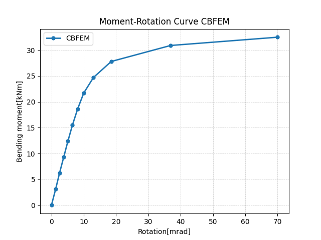
\[ \textsf{\textit{\footnotesize{Fig. 5.3.4 Prediction of behavior of end plate minor axis connection on moment rotational curve CBFEM}}}\]
Tab. 5.3.2 Main characteristics for global behavior
| CM | CBFEM | CM/CBFEM | ||
| Initial stiffness | [kNm/rad] | 16130 | 2232 | 7.23 |
| Design resistance | [kNm] | 31 | 30 | 1,03 |
The results of studies are summarized in the graph comparing resistances by CBFEM and component method; see Fig. 5.3.5. The results show that the difference between methods is up to 14 %. CBFEM predicts in all cases lower resistance compared to CM, which is based on simplification in (Steenhuis et al. 1998). Similar results may be observed in work by (Wang and Wang, 2012).
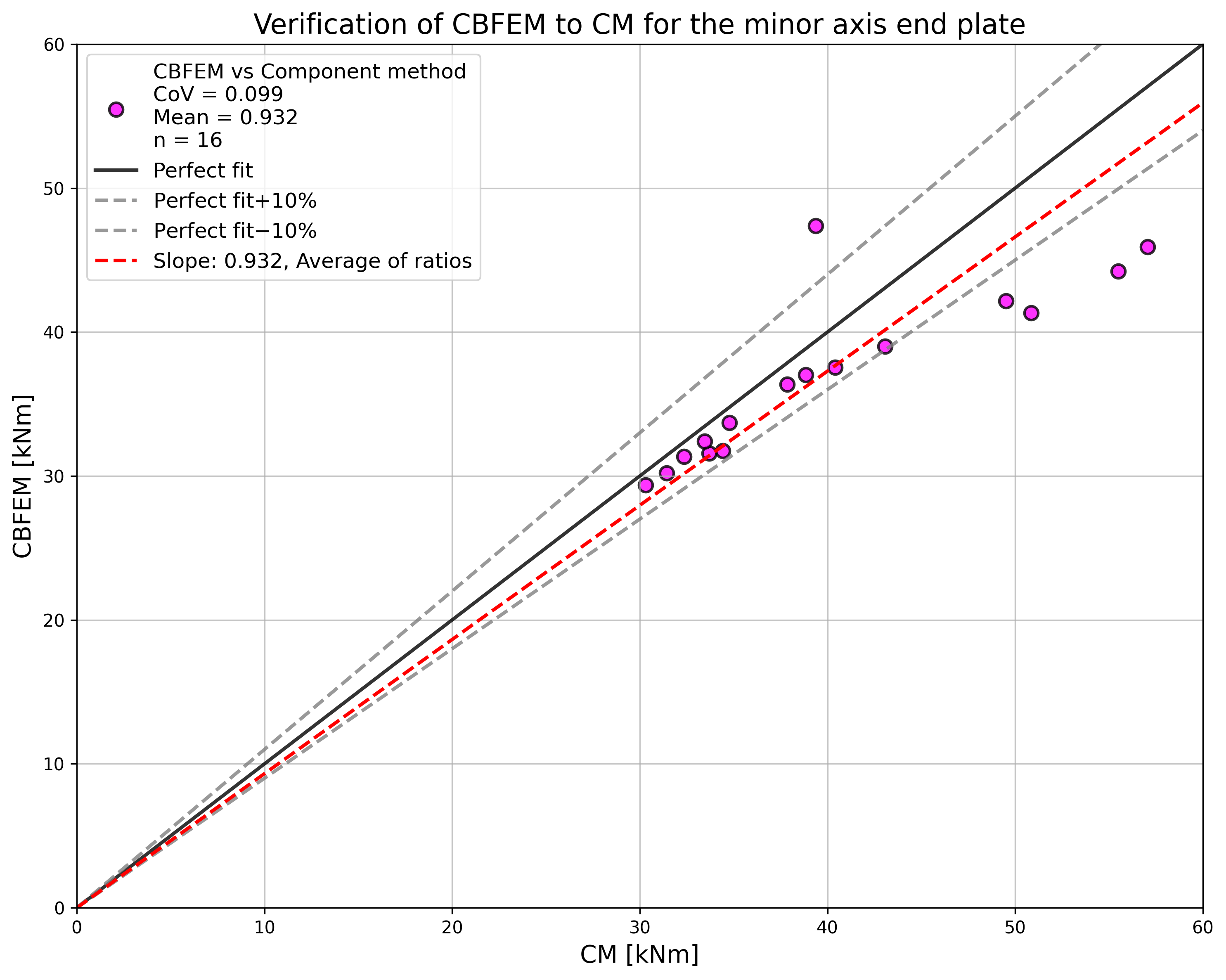
\[ \textsf{\textit{\footnotesize{Fig. 5.3.5 Summary of verification of CBFEM to CM for the end plate minor axis connection}}}\]
Benchmark example
The benchmark case is prepared for the end plate minor axis connection according to Fig. 5.3.1 with modified geometry as summarized below.
Inputs
- Steel S235
- Column HEB 300
- Beam IPE 240
- Bolts 6×M16 8.8
- Welds thickness 5 mm
- End-plate thickness tp = 18 mm
Outputs
- Design resistance in bending MRd = 30 kNm
- Governing component – column web in bending
References
EN 1993-1-5, Eurocode 3, Design of steel structures – Part 1-5: Plated Structural Elements, CEN, Brussels, 2005.
Steenhuis M., Jaspart J. P., Gomes F., Leino T. Application of the component method to steel joints, in Control of the Semi-rigid Behaviour of Civil Engineering Structural Connections Conference, COST C1, Liege, Belgium, 1998, 125-143.
Wang Z., Wang T. Experiment and finite element analysis for the end plate minor axis connection of semi-rigid steel frames, Tumu Gongcheng Xuebao/China Civil Engineering Journal, 45 (8), 2012, 83-89.