Stirnplattenverbindung an der schwachen Achse
Beschreibung
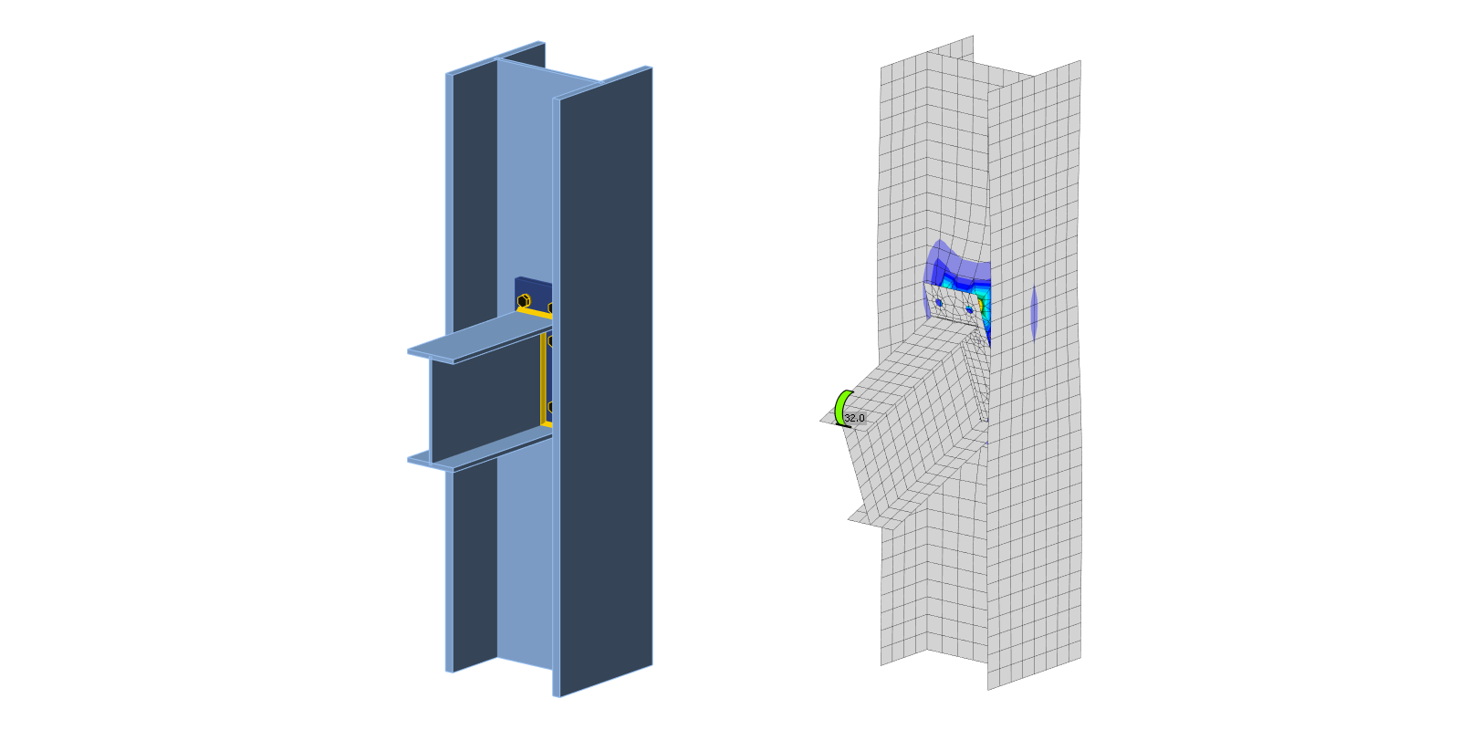
Das CBFEM-Modell (Component-Based Finite Element Method) des Träger-Stützen-Knotens wird anhand der Komponentenmethode (CM) verifiziert. Die verlängerte Stirnplatte mit drei Schraubenreihen ist mit dem Stützensteg verbunden und wird durch ein Biegemoment belastet; siehe Abb. 5.3.1.

\[ \textsf{\textit{\footnotesize{Fig. 5.3.1 Joint geometry - all dimensions in mm}}}\]
Analytisches Modell
Drei Komponenten, die das Verhalten maßgeblich bestimmen, sind die Stirnplatte auf Biegung, der Trägerflansch auf Zug und Druck sowie der Stützensteg auf Biegung. Die Stirnplatte und der Trägerflansch auf Zug und Druck werden gemäß EN 1993-1-8:2005 bemessen. Das Verhalten des Stützenstegs auf Biegung wird nach (Steenhuis et al. 1998) vorhergesagt. Die Ergebnisse von Versuchen an Träger-Stützen-Verbindungen an der schwachen Achse, z. B. (Lima et al. 2009), zeigen eine gute Vorhersage dieser Verbindungsart unter Belastung in der Ebene des angeschlossenen Trägers.
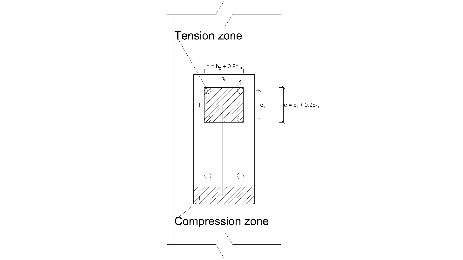
\[ \textsf{\textit{\footnotesize{Fig. 5.3.2 Definition of the tension zone}}}\]
\[F_\mathrm{{local.Rd }}=\min \left(F_\mathrm{{punch.Rd }} ; F_\mathrm{{comb.Rd }}\right)\]
\[F_\mathrm{ {punch.Rd }} = n \cdot \pi\cdot d_\mathrm{m} \cdot t_\mathrm{w c} \cdot f_\mathrm{y} /\left(\sqrt{3} \cdot \gamma_\mathrm{M 0}\right) \quad \text{bolted end plate }\]
\[b = b_0 + 0.9 \cdot d_\mathrm{m}\]
\[c = c_0 + 0.9 \cdot d_\mathrm{m}\]
\[a = L - b\]
\[k= 1 \quad \text{ if }\quad(b+c) / L>0.5\]
\[k=0.7+0.6(b+c) / L \quad \text{ if }\quad(b+c) / L \leq 0.5\]
\[b_\mathrm{m}=L\left[1-0.82 \frac{t_\mathrm{w c}^2}{c^2}\left(1+\sqrt{1+2.8 \frac{c^2}{t_\mathrm{w c} L}}\right)^2\right], \quad \text{ but } \quad b_\mathrm{m} \geq 0\]
\[x_0=L\cdot\left[\left(\frac{t_\mathrm{w c}}{L}\right)^{\frac{2}{3}}+0.23 \frac{c}{L}\left(\frac{t_\mathrm{w c}}{L}\right)^{\frac{1}{3}}\right] \cdot\left(\frac{b-b_\mathrm{m}}{L-b_\mathrm{m}}\right)\]
\[x = 0 \quad b \leq b_\mathrm{m}\]
\[x=-a+\sqrt{a^2-1.5 a c+\frac{\sqrt{3}}{2} t_\mathrm{w c}\left[\pi \sqrt{L\left(a+x_0\right)}+4 c\right]} \quad \text{ if }\quad b>b_\mathrm{m}\]
\[F_\mathrm{c o m b . R d}=k\cdot t_\mathrm{w c}^2 \cdot f_\mathrm{y}\left[\frac{\pi \sqrt{L(a+x)}+2 c}{a+x}+\frac{1.5 c x+x^2}{\sqrt{3} t_\mathrm{w c}(a+x)}\right] / \gamma_\mathrm{M 0}\]
\[\rho = 1 \quad \text{ if }\quad z / (L-b) \leq 1\]
\[\rho = z / (L-b) \quad \text{ if }\quad 1<z / (L-b) \leq 10\]
\[F_\mathrm{g l o b a l . R d}=\frac{F_\mathrm{c o m b . R d}}{2}+\frac{t_\mathrm{w c}^2 f_\mathrm{y}}{4}\left(\frac{2 b}{z}+\pi+2 \rho\right) / \gamma_\mathrm{M 0}\]
\[F_\mathrm{Rd} = \min \left(F_\mathrm{{local.Rd }} ; F_\mathrm{g l o b a l . R d}\right)\]
\[M_\mathrm{Rd} = z \cdot F_\mathrm{Rd}\]
Dabei gilt:
- \(t_\mathrm{w c} \quad\) ist die Dicke des Stützenstegs
- \(f_\mathrm{y} \quad\) ist die Streckgrenze des Stützenstegs
- \(\gamma_{\mathrm{M} 0}\) ist der Teilsicherheitsbeiwert für Stahl
- \(\gamma_{\mathrm{M} 0}\) ist der Teilsicherheitsbeiwert für Stahl
- \(n\) Anzahl der Schraubenreihen in der Zugzone
- \(d_\mathrm{m}\) Diagonaldurchmesser des Schraubenkopfes
- \(b_0\) horizontaler Abstand zwischen den Schrauben
- \(c_0\) vertikaler Abstand zwischen den Schrauben
- \(z\) Hebelarm der Verbindung
- \(F_\mathrm{ {punch.Rd }} \quad\) ist der Widerstand gegen Durchstanzen
- \(F_\mathrm{ {comb.Rd }} \quad\) ist der Widerstand gegen kombiniertes Durchstanzen, Querkraft und Biegung
Numerisches Modell
Die Bewertung basiert auf der maximalen Dehnung gemäß EN 1993-1-5:2006 mit einem Wert von 5 %. Detaillierte Informationen zum CBFEM-Modell sind in Kapitel 3 zusammengefasst.
Verifikation der Tragfähigkeit
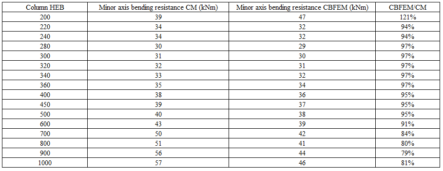
Die Sensitivitätsstudie der Knotentragfähigkeit wurde für Stützenquerschnitte durchgeführt. Die Knotengeometrie ist in Abb. 5.3.1 dargestellt. In Tab. 5.3.1 und in Abb. 5.3.3 sind die Ergebnisse der Berechnungen für den Fall einer vergrößerten Stirnplatte P18 im Verhältnis zum Stützenquerschnitt zusammengefasst.
Tab. 5.3.1 Ergebnisse der Vorhersage der Stirnplattenverbindung an der schwachen Achse für verschiedene Dachbinder
\[ \textsf{\textit{\footnotesize{Fig. 5.3.3 Comparison resistance of end plate minor axis connection predicted by CBFEM and CM}}}\]
Globales Verhalten
Das globale Verhalten wird anhand der Kraft-Verformungskurve dargestellt. Träger IPE 240 ist mit sechs Schrauben M16 8.8 an Stütze HEB 300 angeschlossen. Die Stirnplattengeometrie ist in Abb. 5.3.1 und in Tab. 5.3.1 dargestellt. Der Vergleich der Ergebnisse beider Methoden ist in Abb. 5.3.4 und in Tab. 5.3.2 dargestellt. Beide Methoden liefern ähnliche Bemessungswiderstände. CBFEM ergibt im Allgemeinen eine geringere Anfangssteifigkeit im Vergleich zur CM.
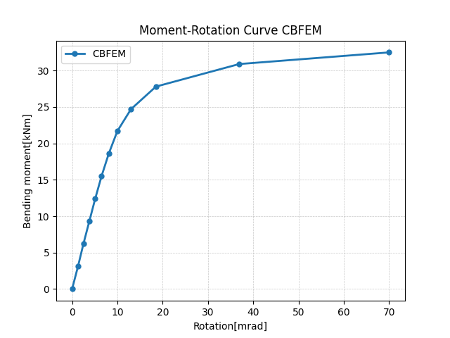
\[ \textsf{\textit{\footnotesize{Fig. 5.3.4 Prediction of behavior of end plate minor axis connection on moment rotational curve CBFEM}}}\]
Tab. 5.3.2 Hauptkennwerte für das globale Verhalten
| CM | CBFEM | CM/CBFEM | ||
| Anfangssteifigkeit | [kNm/rad] | 16130 | 2232 | 7,23 |
| Bemessungswiderstand | [kNm] | 31 | 30 | 1,03 |
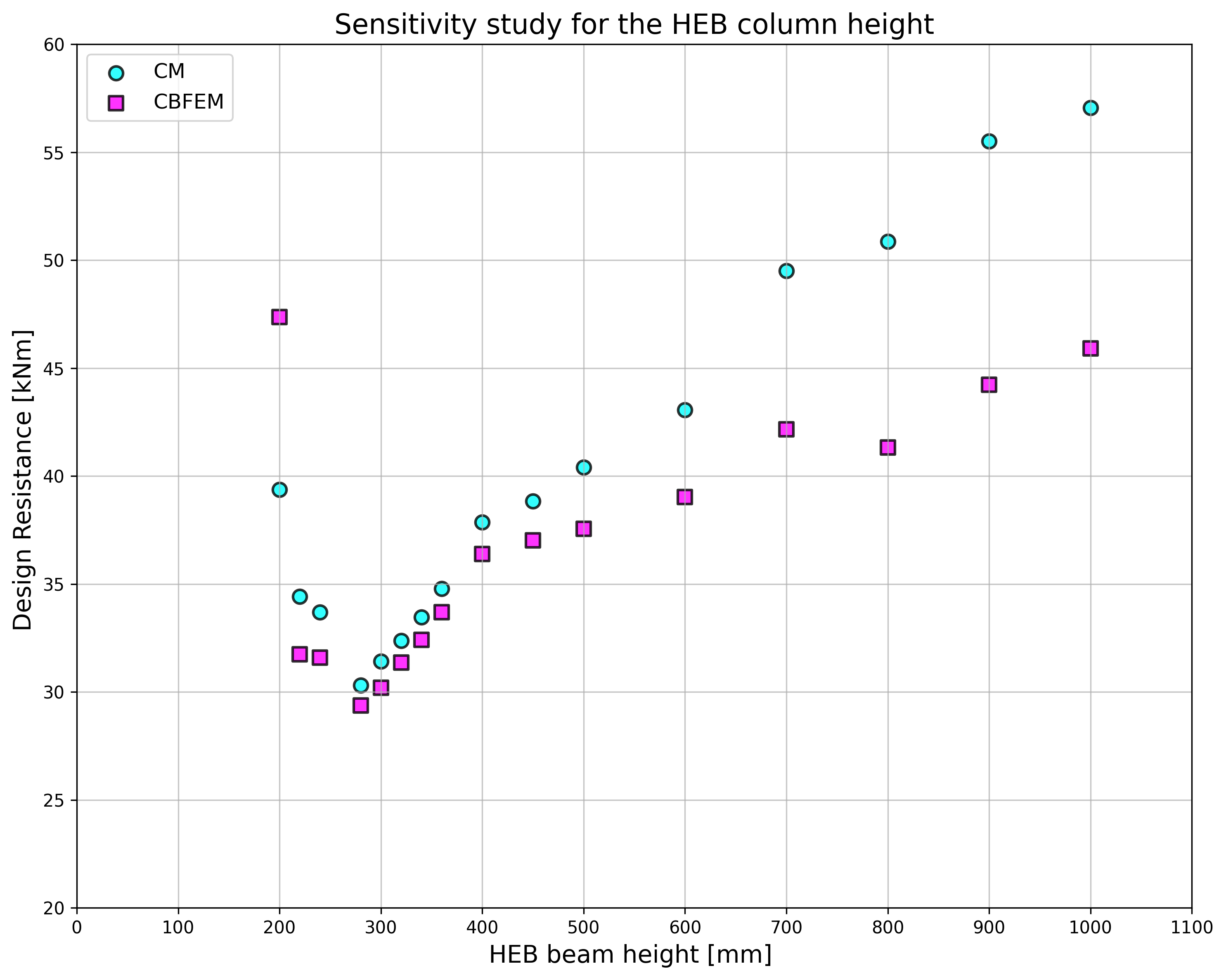
Die Ergebnisse der Studien sind in einem Diagramm zusammengefasst, das die Tragfähigkeiten nach CBFEM und Komponentenmethode vergleicht; siehe Abb. 5.3.5. Die Ergebnisse zeigen, dass die Abweichung zwischen den Methoden bis zu 14 % beträgt. CBFEM liefert in allen Fällen einen geringeren Widerstand im Vergleich zur CM, was auf der Vereinfachung in (Steenhuis et al. 1998) basiert. Ähnliche Ergebnisse sind in der Arbeit von (Wang und Wang, 2012) zu beobachten.
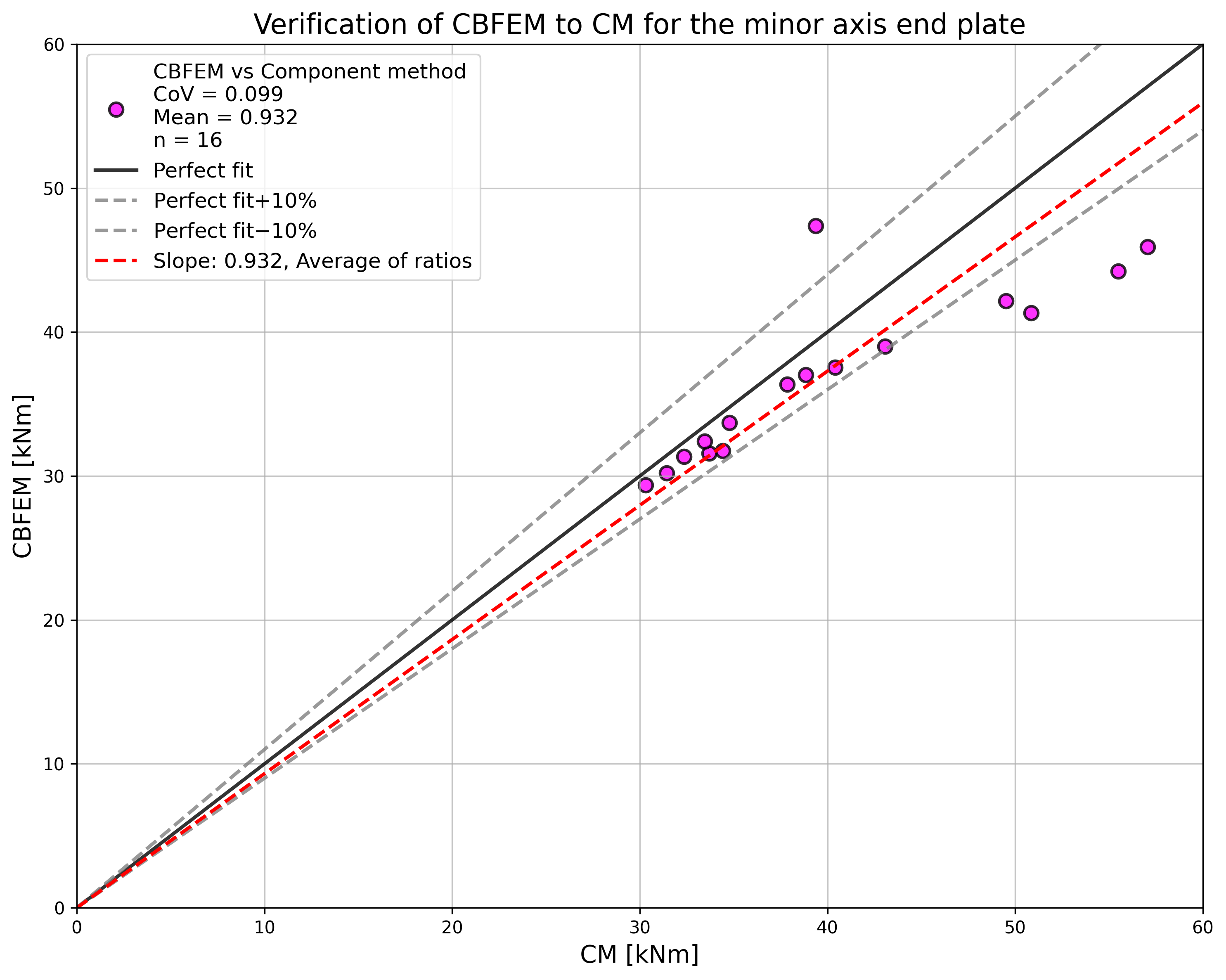
\[ \textsf{\textit{\footnotesize{Fig. 5.3.5 Summary of verification of CBFEM to CM for the end plate minor axis connection}}}\]
Benchmark-Beispiel
Das Benchmark-Beispiel ist für die Stirnplattenverbindung an der schwachen Achse gemäß Abb. 5.3.1 mit modifizierter Geometrie, wie nachfolgend zusammengefasst, vorbereitet.
Eingaben
- Stahl S235
- Stütze HEB 300
- Träger IPE 240
- Schrauben 6×M16 8.8
- Nahtdicke 5 mm
- Stirnplattendicke tp = 18 mm
Ausgaben
- Bemessungswiderstand auf Biegung MRd = 30 kNm
- Maßgebende Komponente – Stützensteg auf Biegung
Literatur
EN 1993-1-5, Eurocode 3, Bemessung und Konstruktion von Stahlbauten – Teil 1-5: Plattenförmige Bauteile, CEN, Brüssel, 2005.
Steenhuis M., Jaspart J. P., Gomes F., Leino T. Application of the component method to steel joints, in Control of the Semi-rigid Behaviour of Civil Engineering Structural Connections Conference, COST C1, Liege, Belgien, 1998, 125–143.
Wang Z., Wang T. Experiment and finite element analysis for the end plate minor axis connection of semi-rigid steel frames, Tumu Gongcheng Xuebao/China Civil Engineering Journal, 45 (8), 2012, 83–89.