The formation of cracks
A characteristic feature of reinforced concrete structures under bending or tensile stress is the occurrence of cracking failure at points where the tensile stress in the concrete exceeds the tensile strength of the concrete. For the durability of the structure and also for the aesthetics of the structure, it is important to ensure that the resulting cracks are as small as possible. The calculation of the crack widths as well as the maximum widths allowed for the different exposure classes are given in EN 1992-1-1, Chapter 7.3.
In the first step of the calculation, it is determined whether the cross-section is cracked or not. The crack width itself is always calculated from the quasi-permanent or frequent load combination (depending on the national annex), but the crack formation has to be checked from all specified SLS combinations. Thus, two cases can occur:
- The maximum tensile stress in the concrete fibers will not exceed the tensile strength of the concrete from any load combination (quasi-permanent ME,qp, frequent ME,fr, or characteristic ME,k), and hence we consider the cross-section without cracks.
\[{{M}_{E,i}}\le {{M}_{cr}}={{f}_{ct,ef}}\frac{{I}_{I}}{h-{{a}_{I}}}\]
- If cracks develop for any of the combinations (quasi-permanent, frequent, or characteristic), i.e. the bending moment developed from the considered load combination is greater than the critical moment Mcr, the cross-section is cracked from that load combination, and the characteristics of the cracked cross-section and the crack width have to be calculated.
\[{{M}_{E,i}}>{{M}_{cr}}={{f}_{ct,ef}}\frac{{I}_{I}}{h-{{a}_{I}}}\]
ME,i . . the bending moment obtained from some SLS load comb. Thus, it can be ME,qp, ME,fr, or ME,k.
fct,ef . . the tensile strength of the concrete at the considered time. If the concrete is older than 28 days, we consider a strength equal to fctm.
Crack width calculation
In a bending-loaded element, the crack formation is divided into 2 phenomena:
- Crack formation phase (stage number 2 in Fig. 1)
- Stabilized crack development (stage number 3 in Fig. 1)
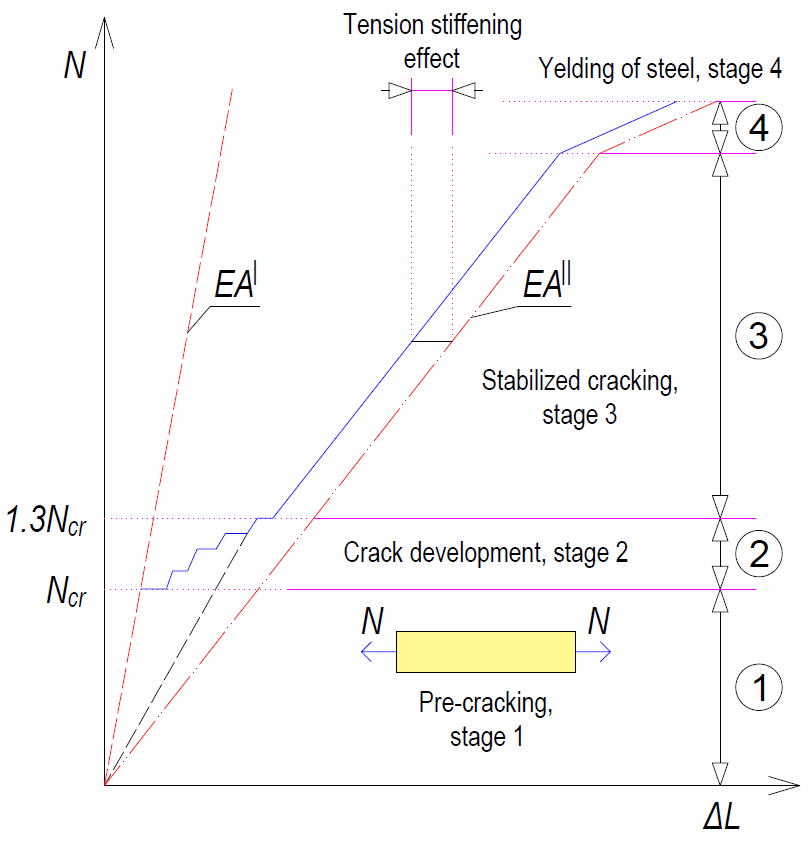
\[ \textsf{\textit{\footnotesize{Fig. 1 Stages of the behavior of the reinforced concrete cross-section during loading}}}\]
Crack development stage
This is the initial part of the process when individual cracks are still gradually appearing until the entire tensile part of the member is affected by cracks that are approximately equally distributed along the length of the member. The first crack is formed when the force in the tensioned strip exceeds the value of the critical force Nr (Critical tensile force, see below), and further cracks develop up to a level of load exerting a force in the tensioned strip equal to approximately 1.3Ncr (phase number 2 in Fig. 1).
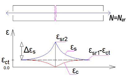
\[ \textsf{\textit{\footnotesize{Fig. 2 Strains of concrete and reinforcement at the moment of the first crack}}}\]
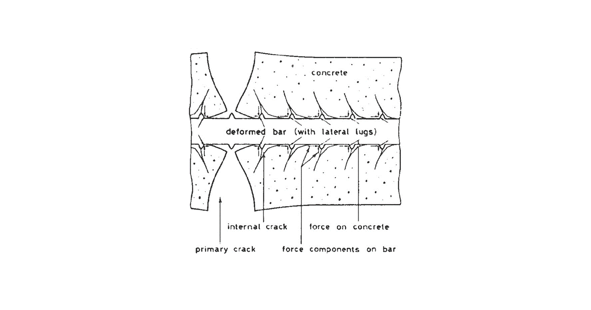
The developing cracks are divided into 2 types - primary and secondary cracks. Primary cracks occur in the tensile fibers when the effective tensile strength of the concrete (fct,eff) is reached. Primary cracks represent the first pattern of cracks (Fig. 2). Shorter secondary cracks are then formed between the primary cracks (Fig. 3). At stresses corresponding to about 1.2 to 1.5 σsr (usually a mean value of 1.3 σsr is considered, where σsr is the stress in the reinforcement at the formation of primary cracks in the tensile zone of the concrete), the development of secondary cracks is also completed.
\[ \textsf{\textit{\footnotesize{Fig. 3 Primary and secondary cracks}}}\]
The crack width at the crack formation stage can be calculated as follows:
\[{{w}_{k}}=2{{l}_{s,\max }}\left( {{\varepsilon }_{sm}}-{{\varepsilon }_{cm}} \right)\]
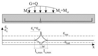
\[ \textsf{\textit{\footnotesize{Fig. 4 Characteristics of the transmission length for the first crack}}}\]
Stabilized cracking stage
After exceeding approximately 1.3 times the critical force in the tensile zone, no new cracks are formed, the number of cracks in the element is stabilized, and only the width of the existing cracks increase with further loading (stage number 3 in Fig. 1).
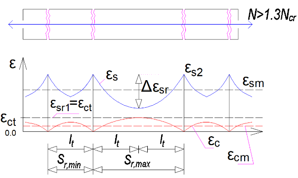
\[ \textsf{\textit{\footnotesize{Fig. 5 Strains of concrete and reinforcement at the stabilized cracking stage}}}\]
The crack width during stable development can be calculated as:
\[{{w}_{k}}={{s}_{r,\max }}\left( {{\varepsilon }_{sm}}-{{\varepsilon }_{cm}} \right)\]
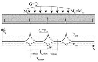
\[ \textsf{\textit{\footnotesize{Fig. 6 Stabilized cracking}}}\]
Critical tensile force
The calculation is based on the Tension Chord Model (TCM). The basic consideration is to calculate the ultimate capacity of a reinforced concrete strip formed by a reinforcing bar of area As,eff surrounded by an effective area of tensile concrete Ac,eff, which is able to resist the tensile stress until the tensile strength fct,eff is exceeded (normally we consider fctm). Assuming a perfect bond between the reinforcement and the concrete, we can consider that until the first crack occurs, the remodeling of the reinforcement and the surrounding concrete is identical. Then the maximum force in the tensile strip just before the first crack Nr can be determined:
\[{{N}_{r}}={{A}_{c,eff}}\cdot {{f}_{ctm}}+{{A}_{s,eff}}\cdot {{\sigma }_{s}}\]
By introducing the substitution
\[{{\alpha }_{e}}={}^{{{E}_{s}}}/{}_{{{E}_{cm}}};{{\rho }_{p,eff}}={}^{{{A}_{s,eff}}}/{}_{{{A}_{c,eff}}}\]
we get:
\[{{N}_{r}}={{A}_{c,eff}}\cdot {{f}_{ctm}}\cdot \left( 1+{{\alpha }_{e}}\cdot {{\rho }_{p,eff}} \right)\]
Just after the formation of the first crack, the entire force Nr is transferred by the reinforcement and thus the stress in the reinforcement passing through the just-formed crack can be calculated as:
\[{{\sigma }_{sr}}=\frac{{{f}_{ctm}}}{{{\rho }_{p,eff}}}\cdot \left( 1+{{\alpha }_{e}}\cdot {{\rho }_{p,eff}} \right)\Rightarrow {{\varepsilon }_{sr}}=\frac{{{f}_{ctm}}}{{{E}_{s}}\cdot {{\rho }_{p,eff}}}\cdot \left( 1+{{\alpha }_{e}}\cdot {{\rho }_{p,eff}} \right)\]
Crack width calculation according to EC 1992-1-1
The following equation is used to calculate the width of cracks on reinforced concrete elements:
\[{{w}_{k}}={{s}_{r,\max }}\left( {{\varepsilon }_{sm}}-{{\varepsilon }_{cm}} \right)\]
sr,max . . . maximum crack spacing
εsm . . . . the average strain of the reinforcement from the load combination, including the effects of tension stiffening.
εcm . . . . average strain of concrete between cracks
Calculation of the strain difference
The difference in the strain of reinforcement and concrete between cracks can be obtained from the equation:
\[{{\varepsilon }_{sm}}-{{\varepsilon }_{cm}}=\frac{{{\sigma }_{s}}-{{k}_{t}}\cdot \frac{{{f}_{ct,eff}}}{{{\rho }_{p,eff}}}\cdot \left( 1+{{\alpha }_{e}}\cdot {{\rho }_{p,eff}} \right)\,}{{{E}_{s}}}\ge 0,6\frac{{{\sigma }_{s}}}{{{E}_{s}}}\]
σs . . . . the stress in the reinforcement in the crack from the load combination under consideration
kt . . . . an empirical coefficient taking into account the average strain, depended on the duration of the load. It can take values of 0.6 for short-term analysis. For the long-term analysis, the reduction of the stiffness of the composite to about 70% is taken into account, so its value is 0.4, which includes the rate of degradation of the cohesion between the reinforcement and the concrete due to time.
αe . . . . the effective ratio of elastic moduli
\[{{\alpha }_{e}}={}^{{{E}_{s}}}/{}_{{{E}_{cm}}}\]
ςp,eff . . . . effective level of reinforcement
\[{{\rho }_{p,eff}}={}^{\left( {{A}_{s,eff}}+{{\xi }^{2}_{1}}A_{p}^{\acute{\ }} \right)}/{}_{{{A}_{c,eff}}}\]
Ac,eff . . . . the effective area of the concrete in tension surrounding the reinforcement (determination of Ac,eff below)
As,eff . . . . the area of bonded reinforcement located in the area of Ac,eff
Ap´ . . . . is the area of pre- or post-tensioned tendons within Ac,eff
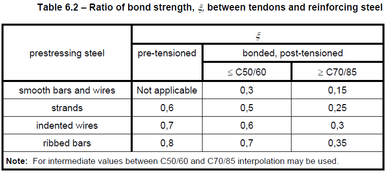
ξ1 . . . . . is the adjusted ratio of bond strength, taking into account the different diameters of prestressing and reinforcing steel:
\[{{\xi }_{1}}=\sqrt{\xi \,\cdot \,\frac{{{\phi }_{s}}}{{{\phi }_{p}}}}\]
ξ . . . the ratio of bond strength of prestressing and reinforcing steel (Table 6.2)
ϕs . . largest bar diameter of reinforcing steel
ϕp . . the diameter or equivalent diameter of prestressing steel
For bundles, Ap is the area of reinforcement in the tendon
\[{{\phi }_{p}}=1,6\sqrt{{{A}_{p}}}\]
For single seven-wire strands where φwire is the wire diameter
\[{{\phi }_{p}}=1,75\,\,{{\phi }_{wire}}\]
For single three-wire strands where φwire is the wire diameter
\[{{\phi }_{p}}=1,20\,\,{{\phi }_{wire}}\]
If only prestressing reinforcement is used to prevent cracking, then the following must be considered.
\[{{\xi }_{1}}=\sqrt{\xi \,}\]
In prestressed members, a minimum area of bonded reinforcement is not required as long as, under the characteristic combination of loading and the characteristic value of prestressing force the tensile stress in any fiber is not greater than the tensile strength of the concrete, fct,eff. (see EN 1992-1-1 ch. 7.3.2 for more details)
The effective area of concrete in tension
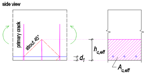
An important but simultaneously the most complicated step of the calculation is determining the effective area of the tensile concrete surrounding the reinforcement. Both the Eurocode and the Model Code consider simple modes of loading, where the reinforced concrete element is loaded by uniaxial bending or tension. The value of the effective height is determined as:
\[{{h}_{c,eff}}=\min \left\{ 2,5\left( h-d \right);\frac{\left( h-x \right)}{3};{}^{h}/{}_{2} \right\}\]
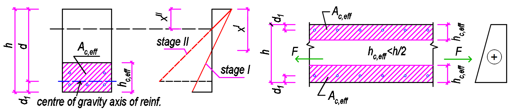
\[ \textsf{\textit{\footnotesize{Fig. 6 Determination of Ac,eff for bent members (left) and members in tension (right)}}}\]
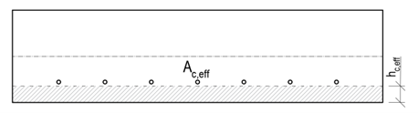
Usually, the value hc,eff = 2,5(h-d) is critical. For tensioned elements, the upper limit is h/2, while for bent elements it is (h-x)/3. However, the area Ac,eff is also limited by the width determined from equation 5(c+ϕ/2). If the spacing of the reinforcements is greater than 5(c+ϕ/2), then the effective area of the tensioned concrete of width 5(c+ϕ/2) is considered for the individual bars.
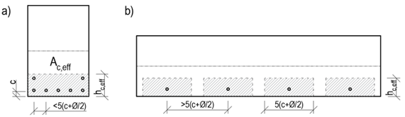
\[ \textsf{\textit{\footnotesize{Fig. 9 Determination of Ac,eff based on reinforcement spacing}}}\]
Maximum crack distance
When calculating the maximum crack distance sr,max, two cases can occur:
- The axial distance of the bonded reinforcement does not exceed a distance of 5(c+ϕ/2) - Fig. 9a
- The axial distance of the bonded reinforcements is greater than 5(c+ϕ/2) - Fig. 9b
The calculation of the maximum crack distance sr,max for the case that the axial distances of the reinforcements do not exceed the value 5(c+ϕ/2) is defined as follows:
\[{{s}_{r,\max }}={{k}_{3}}c+{{k}_{1}}{{k}_{2}}{{k}_{4}}\frac{\phi }{{{\rho }_{p,eff}}}\]
c . . . . . concrete cover value in mm. Since the cover value may be different for the edge reinforcement to both the horizontal and vertical edges, it is recommended to consider the maximum cover value found for the reinforcement under consideration.
ϕ . . . . diameter of the bonded reinforcement. In the case of different reinforcement diameters, the equivalent diameter shall be calculated in accordance with EN 1992-1-1 Equation 7.12.
\[{{\phi }_{eq}}=\frac{{{n}_{1}}\phi _{1}^{2}+{{n}_{2}}\phi _{2}^{2}}{{{n}_{1}}{{\phi }_{1}}+{{n}_{2}}{{\phi }_{2}}}\]
k1 . . . . is a coefficient that takes account of the bond properties of the bonded reinforcement
- k1 = 0,8 for high bond bars
- k1 = 1,6 for bars with an effectively plain surface (e.g. prestressing tendons)
k2 . . . . is a coefficient that takes account of the distribution of strain
- k2 = 1,0 for bending
- k2 = 0,5 for pure tension
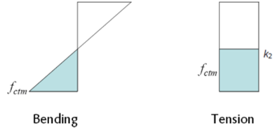
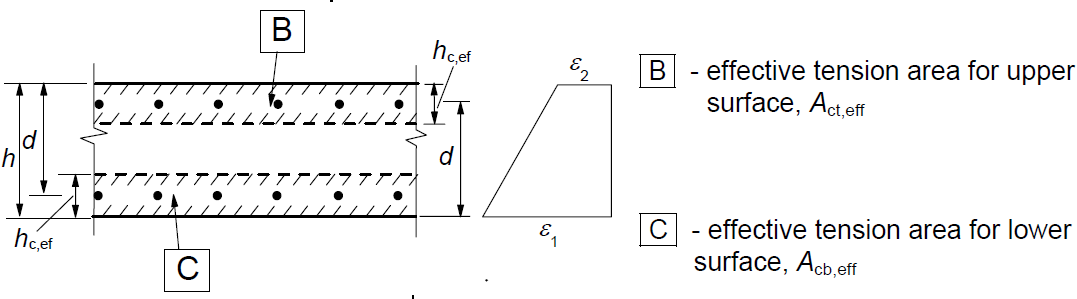
For cases of eccentric tension or for local areas, intermediate values of k2 should be used which may be calculated from the relation:
\[{{k}_{2}}=\frac{{{\varepsilon }_{1}}+{{\varepsilon }_{2}}}{2{{\varepsilon }_{1}}}\]
k3 . . . . coefficient expressing the length of the area close to a crack where the bond between the concrete and the reinforcement is broken. The recommended value of the basic EC k3 = 3,4 may be modified by the National Annex.
k4 . . . . coefficient expresses the relationship between the bond and tensile strength of concrete. The recommended value of the basic EC k4 = 0.425 may be adjusted by the National Annex.
The calculation of the maximum crack distance sr,max for the case that the axial distances of the reinforcements exceed the value 5(c+ϕ/2) is defined as follows:
\[{{s}_{r,\max }}=1,3\left( h-x \right)\]
Maximum crack distance values according to the equation
\[{{s}_{r,\max }}=1,3\left( h-x \right)\]
should always be greater than the values determined by the equation
\[{{s}_{r,\max }}={{k}_{3}}c+{{k}_{1}}{{k}_{2}}{{k}_{4}}{\phi }/{{{\rho }_{p,eff}}}\;\]
otherwise, it is recommended to consider the larger distance obtained from the above equations. The equation for the strain in the concrete/reinforcement is not modified for the case of the large axial distance of the reinforcement. In areas with controlled crack widths, the axial distance of individual reinforcements should not be greater than 5(c+ϕ/2).
Crack width calculation implemented in RCS
Determination of effective area Ac,eff
Because it is not so straightforward to determine which reinforcement can be considered as longitudinal crack-resisting reinforcement, Ac,eff is determined by using the following iterative process.
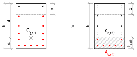
- Of all the reinforcement acting in tension, the tensile force center Cg,s,1 is determined. The effective depth of the reinforcement d is the distance between Cg,s, and the most compressed concrete fiber calculated in the direction of the resultant bending moment. At the same time, the position of the neutral axis and the height of the compressed area x for the cracked cross-section are determined. This makes it possible to determine the effective height hc,eff:
\[{{h}_{c,eff}}=\min \left\{ 2,5\left( h-d \right);\frac{\left( h-x \right)}{3};{}^{h}/{}_{2} \right\}\]
- By excluding all reinforcement that lie outside the Ac,eff,1, the new center of the reinforcement Cg,s,2 is determined, together with the new effective depth of the reinforcement d, effective height hc,eff is determined in the same way as in the previous step, only with changed input values.
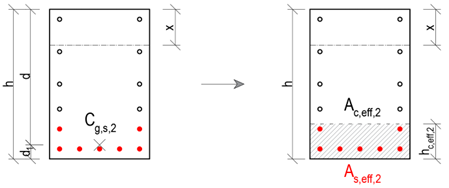
Again, it is checked that all the tensioned reinforcement under consideration lies in the Ac,eff,2. If this condition is satisfied, the iteration can be terminated and the values of hc,eff,2, Ac,eff,2 and As,eff,2 are displayed as the resulting values in IDEA StatiCa RCS.
Possible cases of crack width calculation
In general, three cases can occur when calculating crack widths:
- The tensile reinforcement lies in the region Ac,eff, with the axial distance of the individual reinforcements being less than 5(c+ϕ/2). Then the following definitions are used for the calculation:
\[{{s}_{r,\max }}={{k}_{3}}c+{{k}_{1}}{{k}_{2}}{{k}_{4}}\frac{\phi }{{{\rho }_{p,eff}}}\]
\[{{\varepsilon }_{sm}}-{{\varepsilon }_{cm}}=\frac{{{\sigma }_{s}}-{{k}_{t}}\,\cdot \,\frac{{{f}_{ct,eff}}}{{{\rho }_{p,eff}}}\,\cdot \,\left( 1+\,{{\alpha }_{e}}\cdot \,{{\rho }_{p,eff}} \right)\,\,}{{{E}_{s}}}\ge 0,6\frac{{{\sigma }_{s}}}{{{E}_{s}}}\]
- The tensile reinforcement lies in the Ac,eff, with the axial distance of the individual reinforcements exceeding the distance 5(c+ϕ/2). Then the following definitions are used for the calculation:
\[{{s}_{r,\max }}=1,3\left( h-x \right)\]
\[{{\varepsilon }_{sm}}-{{\varepsilon }_{cm}}=\frac{{{\sigma }_{s}}-{{k}_{t}}\,\cdot \,\frac{{{f}_{ct,eff}}}{{{\rho }_{p,eff}}}\,\cdot \,\left( 1+\,{{\alpha }_{e}}\cdot \,{{\rho }_{p,eff}} \right)\,\,}{{{E}_{s}}}\ge 0,6\frac{{{\sigma }_{s}}}{{{E}_{s}}}\]
- The tensile reinforcement does not lie in the Ac,eff (this may be caused, for example, by thick cover).
In this case it would not be possible to calculate the width of the cracks. Therefore, the calculation of the effective height hc,eff is modified as follows:
\[{{h}_{c,eff}}=\min \left\{ 2,5\left( h-d \right);h/2 \right\}\]
At the same time, the following nonconformity is displayed:
The effective concrete area in tension surrounding the reinforcement or prestressing tendons of depth hc,eff, where hc,eff is the lesser of 2.5(h – d) or h/2. Considering value as (h – x)/3, the reinforcement is out of the effective area of concrete in tension, and therefore it would not be possible to calculate crack width according to clause 7.3.4.