Warping of members – Load in shear center
Description of the analysis model
Including the condensed elements in the analysis model, the members became much longer. In IDEA StatiCa Connection version 20.1 and below, the members had, by default, a length of 1.5×h for open sections and 2×h for closed sections. The ends of the members consisting of shell elements were stiffened by links, through which the load is imposed. These links make the end of the member stiff in warping.
In IDEA StatiCa Connection version 21.0 and above, the condensed elements are added behind the parts of members consisting of shell elements. The condensed element has the same properties as if composed of shell elements with elastic material properties. The length of the condensed element is 4×h for the stress-strain analysis type. The loads are imposed at the end of the condensed elements, so the connections are much less affected by the stiffening. The model is more effective, and it allows to decrease the default member length consisting of shell elements to 1.25×h for both open and closed sections.
Read more about the topic in the Condensed superelements - invisible but essential article.
That means the member lengths with default settings increased from 1.5×h to 5.25×h and 2×h to 5.25×h for open sections and closed sections, respectively. The warping develops through the member length, according to Vlasov's theory, and the warping moment does not increase linearly but rather exponentially.
So in previous versions (20.1 and downward), the warping moment had a small effect, but now it may be very relevant; it is now about 6.5× higher if the warping is restrained in the connection. Of course, the utilization of plates, bolts, and welds rises as well.

Note that the warping moment depends on the length of the member, where the load is applied, boundary conditions at both ends, or some intermediate supports or stiffeners. So the user should be aware that the warping moment is still inaccurate. Just now the member is longer, so it is closer to the real magnitude if the torsion can be justified.

Is the member really warping?
The essential question is if the torsion and warping of a member are really possible. Often, the member's upper flange is held by a floor slab that effectively restrains any torsion of the member. In that case, the torsion and warping may be neglected, and it is not necessary to design this member and its connection against these forces.
If the top flanges of these rafters are really restrained against lateral movement, this failure mode is not relevant and internal forces should be modified accordingly.
How to get rid of the unwanted torsion moment?
There are two ways how to neglect the torsion moment in the Connection application.
Let's have a look at each option individually.
Equivalent torsion moment calculation
All members are loaded through their center of gravity. For doubly symmetrical cross-sections (e.g. I, H, RHS, CHS sections), the center of gravity is at the same location as the center of shear. If the load passes through the center of shear, the shear force does not cause any additional torsion.
However, for other members with only one or none axis of symmetry, the position of the center of shear is shifted from the center of gravity. The shear load is applied through the center of gravity, and the torsion moment is generated. This torsion moment is equal to the shear force times the distance between the center of gravity and the center of shear.
If an engineer assumes that the member cannot rotate, this torsion moment should be balanced by an opposite torsion moment in the applied load effects. Be aware that this balancing torsion moment will be shown in the unbalanced forces when using the Loads in Equilibrium option.

Now, let's show it in a practical example.
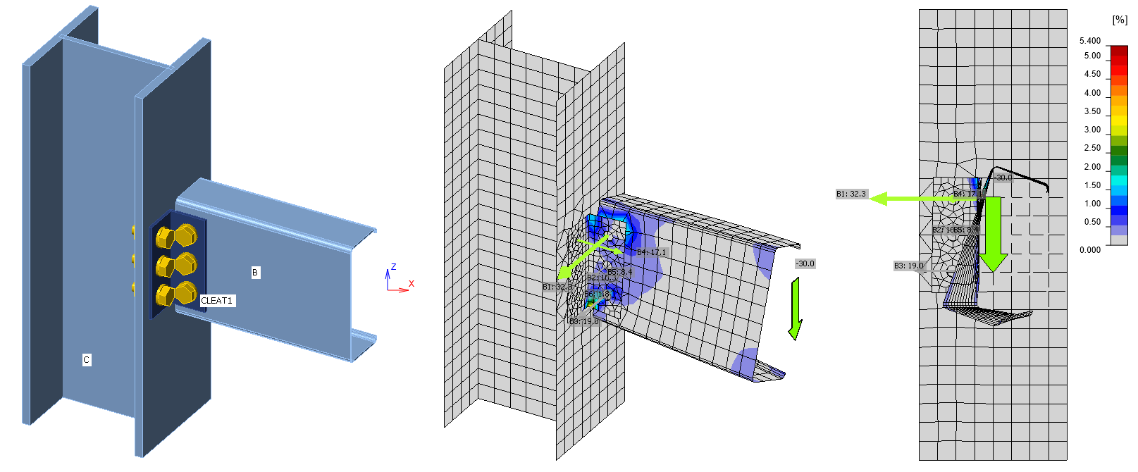
We have a connection with a U-shaped beam. See the cross-section, its characteristics, and loads in the image below.

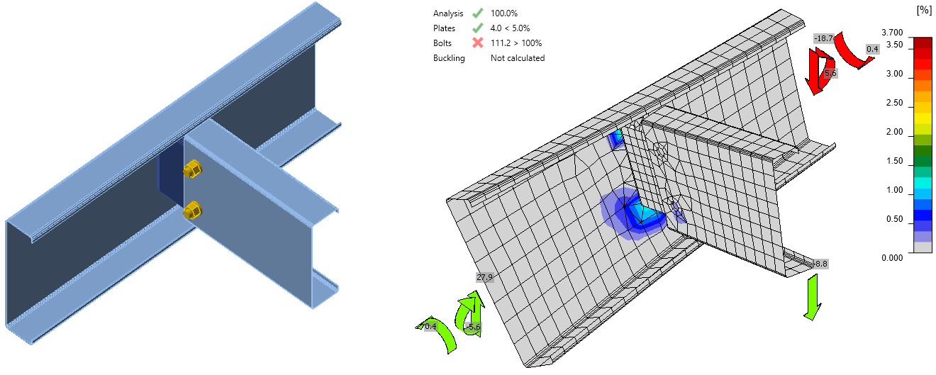
For example, this beam gets twisted and shows unrealistic stress and deformation trend, and the code-checks are affected. In reality, the beam is prevented from torsion along its whole length, so there should not be such an effect.

To correct the model, an equivalent contra torsion moment M'x has to be calculated and added to the load effects for this member. In this example, for LE1, the moment M'x = Vz * y0 = 1502 * 0,113 = 170 kNm has to be added extra.

Be aware that the decision of whether or not to balance the torsion lies with the engineer. There are clauses in the codes or publications that may help.
Lateral torsional restraint operation
The other way of stabilizing a member is using the Lateral torsional restraint operation.
To learn more about the functionality, read the following articles: