Încovoierea de torsiune a elementelor – Încărcare în centrul de forfecare
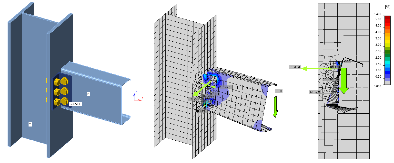
Descrierea modelului de analiză
Prin includerea elementelor condensate în modelul de analiză, elementele au devenit mult mai lungi. În IDEA StatiCa Connection versiunea 20.1 și anterioară, elementele aveau, implicit, o lungime de 1,5×h pentru secțiuni deschise și 2×h pentru secțiuni închise. Capetele elementelor alcătuite din elemente de tip coajă erau rigidizate prin legături, prin intermediul cărora se aplică încărcarea. Aceste legături fac capătul elementului rigid la încovoiere de torsiune.
În IDEA StatiCa Connection versiunea 21.0 și ulterioară, elementele condensate sunt adăugate în spatele porțiunilor de elemente alcătuite din elemente de tip coajă. Elementul condensat are aceleași proprietăți ca și cum ar fi compus din elemente de tip coajă cu proprietăți de material elastic. Lungimea elementului condensat este de 4×h pentru tipul de analiză efort-deformație. Încărcările sunt aplicate la capătul elementelor condensate, astfel încât îmbinările sunt mult mai puțin afectate de rigidizare. Modelul este mai eficient și permite reducerea lungimii implicite a elementelor alcătuite din elemente de tip coajă la 1,25×h atât pentru secțiunile deschise, cât și pentru cele închise.
Citiți mai multe despre acest subiect în articolul Supraelemente condensate - invizibile, dar esențiale.
Aceasta înseamnă că lungimile elementelor cu setări implicite au crescut de la 1,5×h la 5,25×h și de la 2×h la 5,25×h pentru secțiunile deschise, respectiv închise. Încovoierea de torsiune se dezvoltă pe lungimea elementului, conform teoriei lui Vlasov, iar momentul de încovoiere de torsiune nu crește liniar, ci mai degrabă exponențial.
Astfel, în versiunile anterioare (20.1 și mai vechi), momentul de încovoiere de torsiune avea un efect redus, dar acum poate fi foarte relevant; acesta este acum de aproximativ 6,5× mai mare dacă încovoierea de torsiune este reținută în îmbinare. Desigur, gradul de utilizare al plăcilor, buloanelor și sudurilor crește de asemenea.

Rețineți că momentul de încovoiere de torsiune depinde de lungimea elementului, de locul unde se aplică încărcarea, de condițiile la limită la ambele capete sau de eventualele reazeme intermediare sau elemente de rigidizare. Prin urmare, utilizatorul trebuie să fie conștient că momentul de încovoiere de torsiune este în continuare aproximativ. Acum elementul este mai lung, deci este mai aproape de valoarea reală dacă torsiunea poate fi justificată.

Elementul se răsucește cu adevărat?
Întrebarea esențială este dacă torsiunea și încovoierea de torsiune a unui element sunt cu adevărat posibile. Adesea, talpa superioară a elementului este reținută de o placă de planșeu care împiedică efectiv orice torsiune a elementului. În acest caz, torsiunea și încovoierea de torsiune pot fi neglijate și nu este necesar să se dimensioneze acest element și îmbinarea sa la aceste forțe.
Dacă tălpile superioare ale acestor grinzi sunt cu adevărat reținute împotriva deplasării laterale, acest mod de cedare nu este relevant și forțele interioare trebuie modificate în consecință.
Cum se elimină momentul de torsiune nedorit?
Există două modalități de a neglija momentul de torsiune în aplicația Connection.
- Calculul momentului echivalent
- Utilizarea operației de reținere laterală la flambaj lateral-torsional
Să analizăm fiecare opțiune în parte.
Calculul momentului de torsiune echivalent
Toate elementele sunt încărcate prin centrul lor de greutate. Pentru secțiunile transversale dublu simetrice (de ex. secțiuni I, H, RHS, CHS), centrul de greutate se află în același loc cu centrul de forfecare. Dacă încărcarea trece prin centrul de forfecare, forța tăietoare nu produce nicio torsiune suplimentară.
Cu toate acestea, pentru alte elemente cu o singură axă de simetrie sau fără axă de simetrie, poziția centrului de forfecare este decalată față de centrul de greutate. Încărcarea prin forță tăietoare este aplicată prin centrul de greutate și se generează un moment de torsiune. Acest moment de torsiune este egal cu forța tăietoare înmulțită cu distanța dintre centrul de greutate și centrul de forfecare.
Dacă un inginer presupune că elementul nu se poate roti, acest moment de torsiune trebuie echilibrat de un moment de torsiune opus în efectele de încărcare aplicate. Rețineți că acest moment de torsiune de echilibrare va fi afișat în forțele neechilibrate atunci când se utilizează opțiunea Încărcări în echilibru.

Acum, să ilustrăm aceasta printr-un exemplu practic.
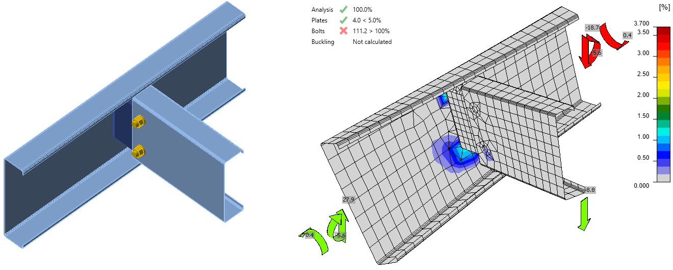
Avem o îmbinare cu o grindă în formă de U. Consultați secțiunea transversală, caracteristicile acesteia și încărcările în imaginea de mai jos.

De exemplu, această grindă se răsucește și prezintă o tendință nerealiste de tensiune și deformație, iar verificările conform codului sunt afectate. În realitate, grinda este împiedicată să se răsucească pe toată lungimea sa, deci nu ar trebui să existe un astfel de efect.

Pentru a corecta modelul, trebuie calculat un moment de torsiune echivalent contrar M'x și adăugat la efectele de încărcare pentru acest element. În acest exemplu, pentru LE1, momentul M'x = Vz * y0 = 1502 * 0,113 = 170 kNm trebuie adăugat suplimentar.

Rețineți că decizia de a echilibra sau nu torsiunea aparține inginerului. Există prevederi în coduri sau publicații care pot fi de ajutor.
Operație de reținere laterală la flambaj lateral-torsional
O altă modalitate de stabilizare a unui element este utilizarea operației de reținere laterală la flambaj lateral-torsional.
Pentru a afla mai multe despre această funcționalitate, citiți următoarele articole: