Temporary Splice Connection (AISC)
This verification example was prepared by Mark D. Denavit and Kayla Truman-Jarrell in a joint project of The University of Tennessee and IDEA StatiCa.
1 Introduction
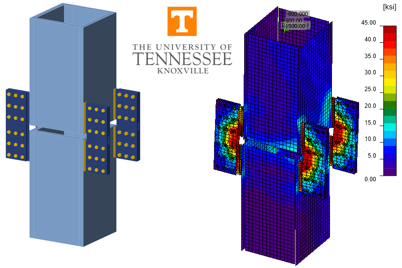
A comparison between the component-based finite element method (CBFEM) and traditional calculation methods used in US practice for the design of a temporary splice connection (Fig. 1 and Fig. 2) is presented in this study. The connection is intended to temporarily support an upper column above a lower column while the permanent welded splice connection between the two members is made. The columns are built-up box members with outside dimensions of 32 in. square and 2.5 in. thick walls. Lugs are fillet welded near each corner of both the upper and lower columns then two strap plates are bolted to each pair (upper and lower) of lugs. All plate is ASTM A572 Gr. 50, all bolts are 7/8 in. diameter A325 in standard holes (threads not excluded from the shear plane), and all weld material is E70XX. Loading on the upper column consists of combined axial compression, shear in two directions, biaxial bending moment, and torsion.
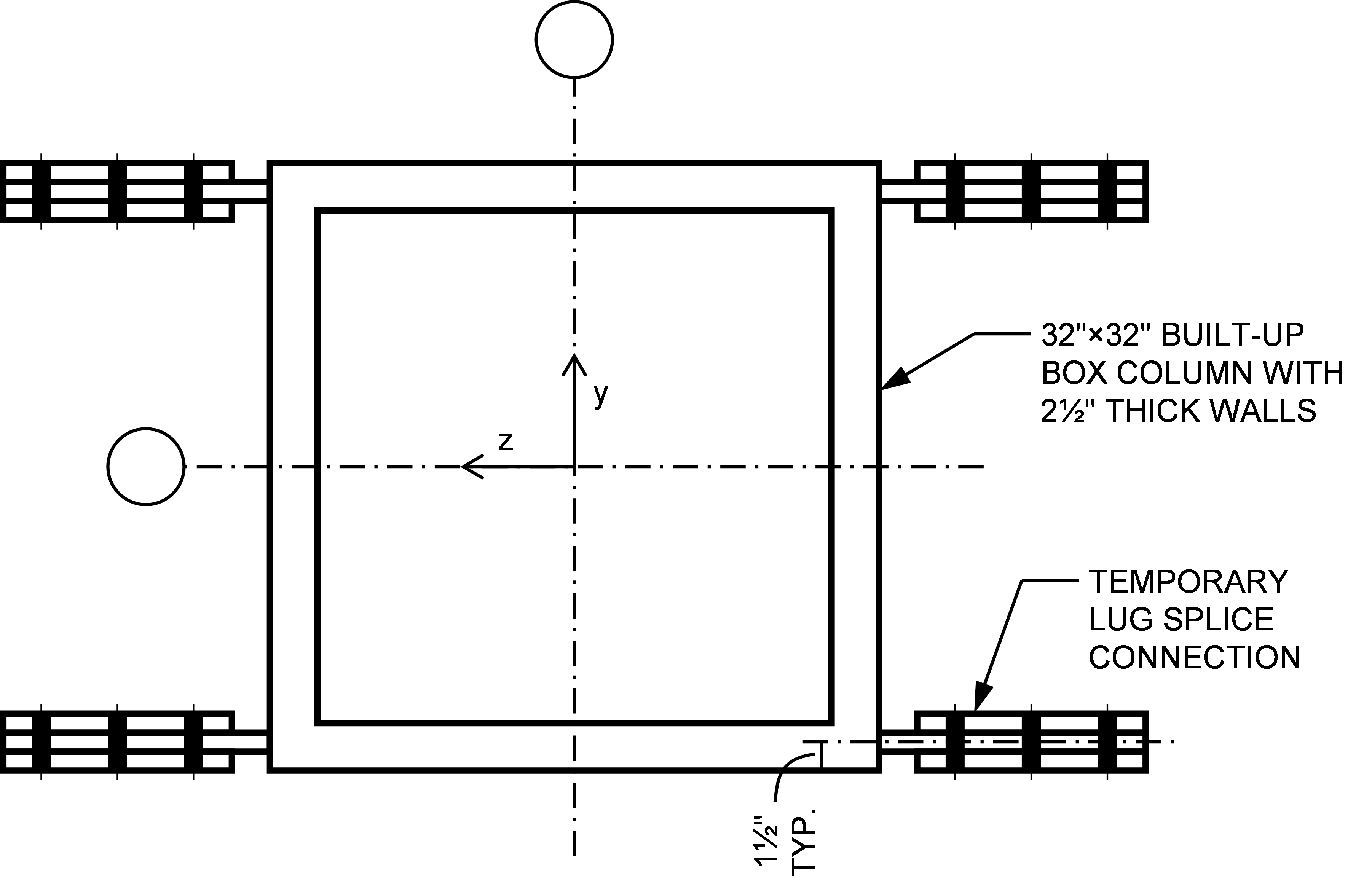
Fig. 1 Schematic plan view of column and temporary splice connection investigated in this study
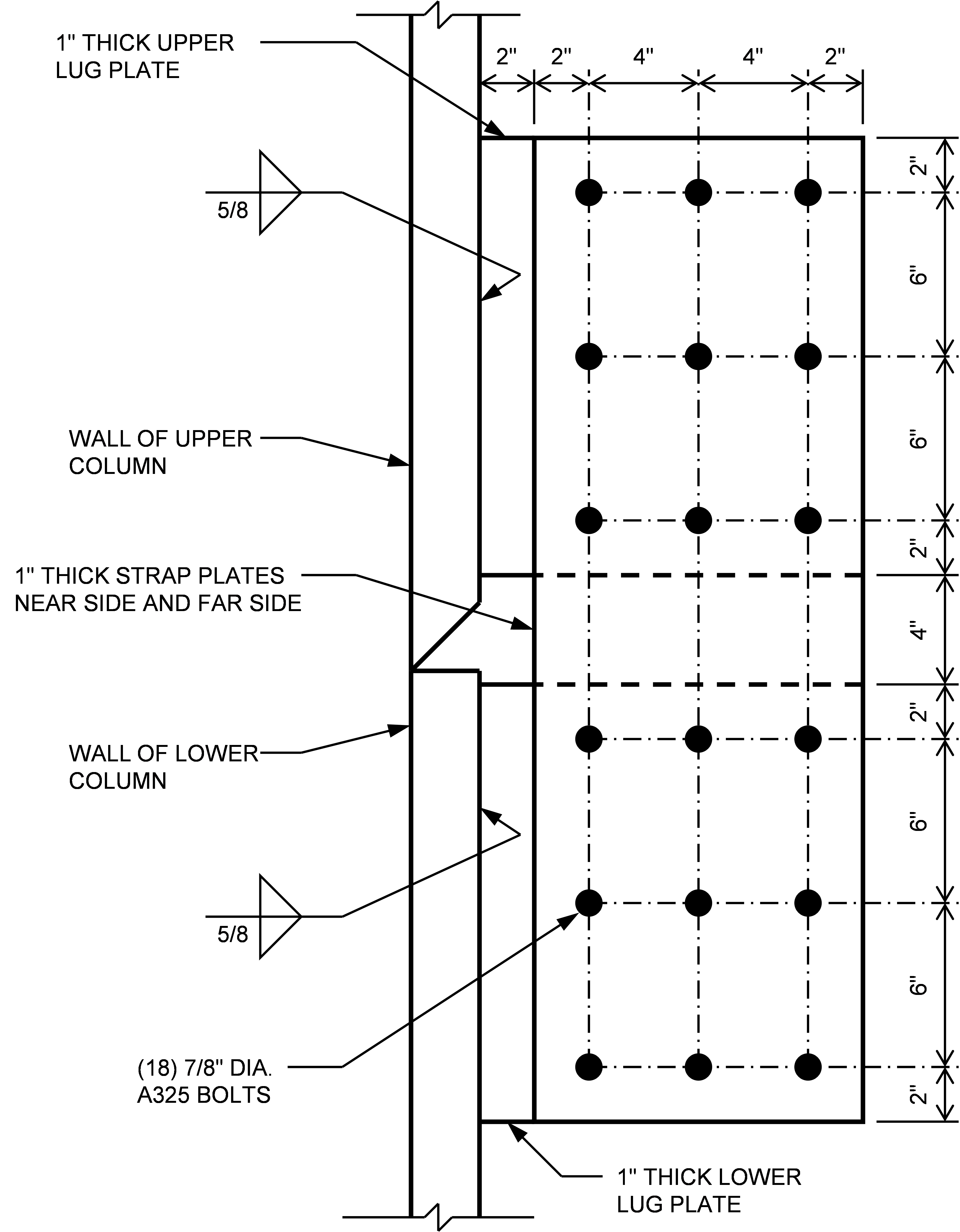
Fig. 2 Schematic detail of temporary lug splice connection investigated in this study
There are no established traditional calculation methods for this connection. The objective of this study is to describe how an engineer might approach the problem using traditional calculations, the limitations they may encounter using the traditional calculations, and how they might use traditional calculations to gain trust in CBFEM results.
The traditional calculations in this work are based upon the requirements for load and resistance factor design (LRFD) in the AISC Specification (2016). The CBFEM results were obtained from IDEA StatiCa Version 21.1. The model of the connection is shown in Fig. 3. Contact bearing between the upper and lower columns is neglected and the bevel in the upper column is not modeled in IDEA StatiCa.
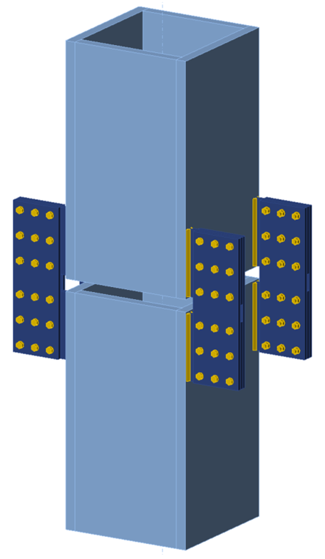
Fig. 3 Temporary splice connection modeled in IDEA StatiCa.
The load path for this connection initiates in the upper column. Loads are transferred through the upper fillet welds to the upper lug plates, then through the upper bolt groups to the strap plates, then through the lower bolt groups to the lower lugs, then through the lower fillet welds to the lower column. For the purposes of this study, the columns are assumed to have adequate strength, therefore evaluation of this connection involves a check of each of the following components:
- Upper fillet welds
- Upper lug plates
- Upper bolt groups
- Strap plates
- Lower bolt groups
- Lower lug plates
- Lower fillet welds
The loading condition dictates which limit states apply to each of these components. The complex combined loading applied to the upper column makes evaluation using traditional calculations difficult. While IDEA StatiCa can handle the general loading condition without difficulty, simplified loading conditions will be examined as points of comparison, to better understand the behavior of the connection, and to build trust in the analysis results.
For each type of load, traditional calculations will be evaluated first, essentially forming a hypothesis of the behavior and strength of the connection. Then IDEA StatiCa analyses are performed to test the hypothesis. Agreement between the traditional calculations and IDEA StatiCa results confirms the hypothesis and increases confidence in both methods. Disagreement between the traditional calculations and IDEA StatiCa requires further investigation.
2 Axial Load
To approach evaluation of this connection by hand, a simplified model of the connection upon which hand calculations can be performed must be developed. When subjected to axial compression, each lug splice connection can be reasonably simplified to a two-dimensional beam model like shown in Fig. 4. Hinges are included in the model at a distance “x” from the face of the column to make the model statically determinant.
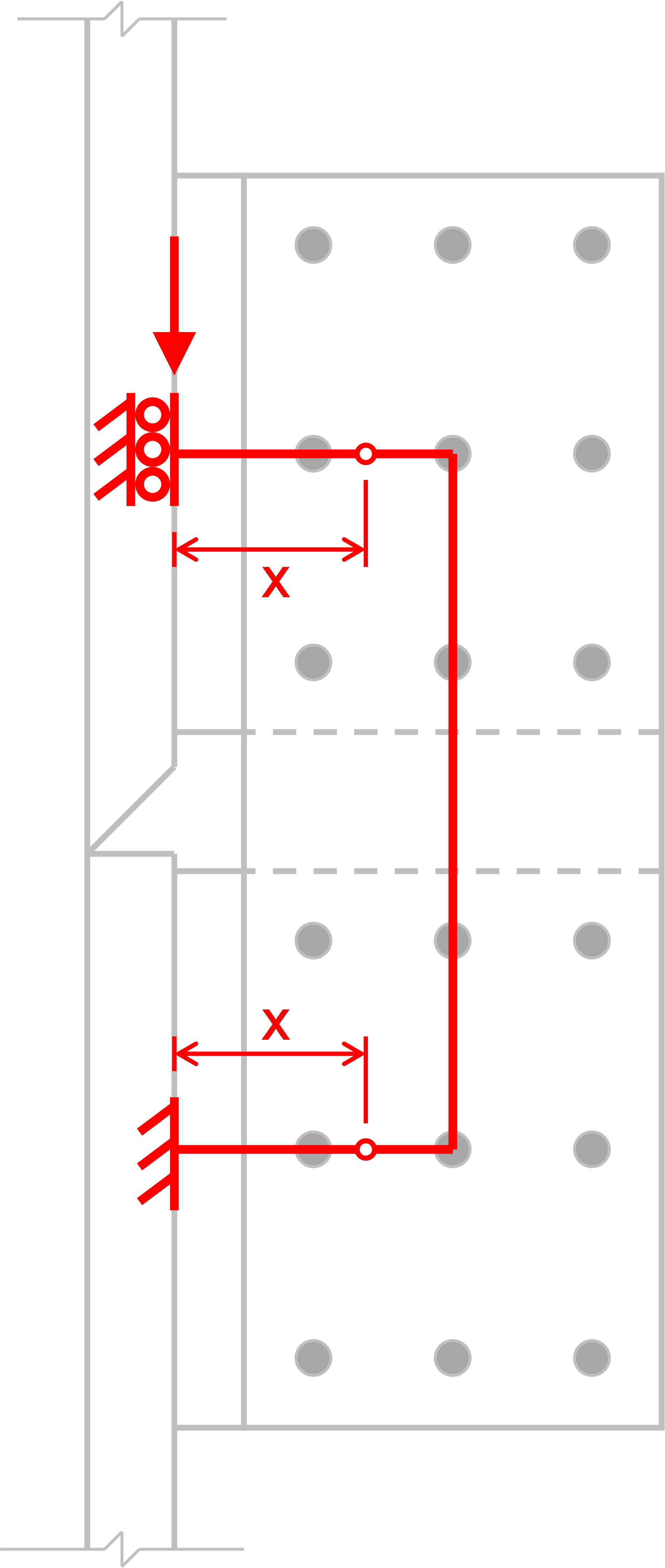
Fig. 4 Simplified model of lug splice connection for axial loads
With this model, the required strength of each component can be computed, and design checks can be performed, starting with the welds, lug plate material adjacent to the welds, and the bolts. Both the welds and the bolt groups are eccentrically loaded. The strength of the welds can be determined as a function of x using Table 8-4 of the AISC Manual (AISC 2017). The strength of the lug plate material adjacent to the weld is controlled by shear and flexural yielding and can be evaluated using the following interaction equation based on Drucker (1956).
\[ \left ( \frac{V_u}{\phi V_n} \right ) ^4 + \frac{M_u}{\phi M_n} \le 1 \]
where, Vu is the required shear strength of the lug plate, equal to one-fourth of the compression load applied to the upper column; ϕVn is the design shear strength of the lug plate, equal to 480 kips; Mu is the required flexural strength of the lug plate, equal to Vux; and ϕMn is the design flexural strength of the lug plate, equal to 2,880 kip-in.
The strength of the bolt group can be determined as a function of x using Tables 7-10 and 7-11 of the AISC Manual (AISC 2017). Interpolation between these tables is necessary since the bolts are spaced at 4 in. horizontally. Note that the design shear strength of an individual bolt in this connection is 48.7 kips for the governing limit state of bolt shear rupture (bearing and tearout do not control for this connection). The maximum permitted vertical load in each lug for each of the limit states is plotted in Fig. 5.
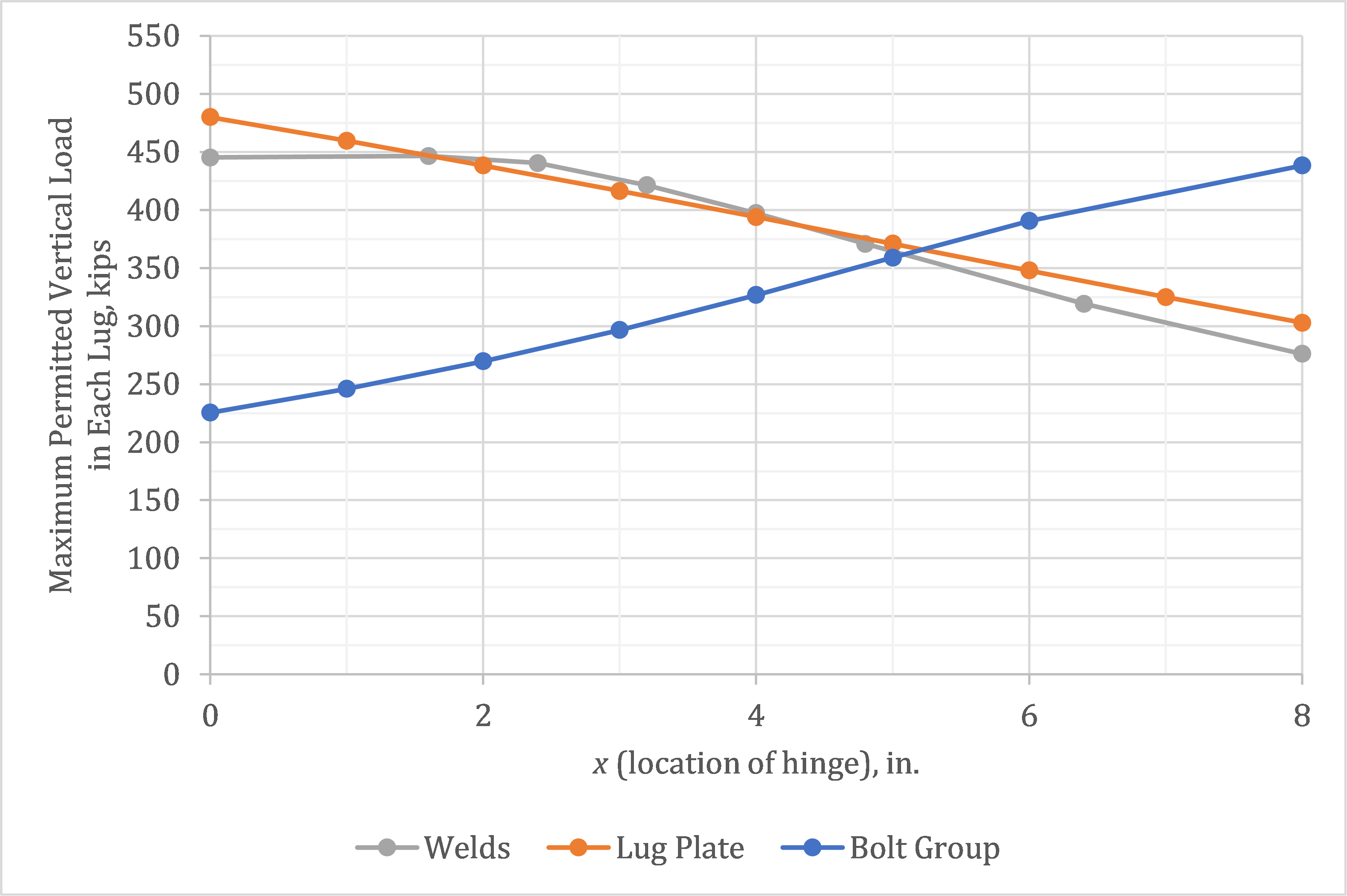
Fig. 5 Design strength for select limit states as a function of the location of the hinge
The “actual” location of the hinges is unknown and must be assumed. By the lower bound theorem of limit analysis, if a distribution of forces within a connection can be found, which is in equilibrium with the external load and which satisfies the limit states, then the externally applied load is less than or at most equal to the load that would cause connection failure (Tamboli 2016). Therefore, any assumption of the location of the hinge will result in a safe design. The most favorable assumed location is approximately x = 5 in., where the strength of the welds and bolt group both equal approximately 360 kips. To complete the design, other limits states, including shear rupture of the lug plate and those associated with the strap plates, need to be evaluated for this load. However, these other limit states do not control, thus the maximum permitted applied compression load on the column is 4×360 kips = 1,440 kips.
With a hypothesis of the behavior and strength of the connection under axial load in place, the connection can be analyzed using IDEA StatiCa to evaluate the hypothesis. The maximum permitted axial compression load per IDEA StatiCa is 1,324 kips. This value was determined iteratively by adjusting the applied load input to a value that the program deems safe but if increased by a small amount (e.g., 1 kip) the program would deem unsafe. The strength of the welds and bolts controls with both at 100% utilization in IDEA StatiCa.
The behavior of the connection as observed in the IDEA StatiCa results is consistent with the behavior assumed in the traditional calculations. The deformed shape and plastic strain results (Fig. 6) show in-plane bending of the lug splice connections and weld groups. The bolt forces (Fig. 7) show in-plane bending of the bolt groups. The strength per IDEA StatiCa is 8% lower than estimated by traditional calculations, a relatively close comparison that is consistent with previous investigations of eccentrically loaded bolt and weld groups.
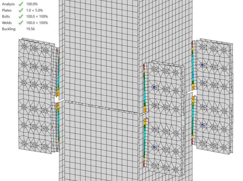
Fig. 6 Plastic stain at 1324 kips applied compression (deformation scale factor = 10)
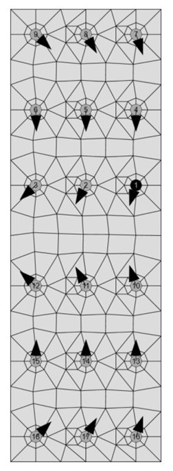
Fig. 7 Bolt forces in strap plate at 1324 kips applied compression
The close agreement between traditional calculations and IDEA StatiCa brings confidence to both results. However, further exploration of the IDEA StatiCa results can bring additional confidence. A buckling analysis can be performed to confirm the appropriateness of neglecting geometric nonlinearity (i.e., P-Δ effects). The buckling factor for this connection at the maximum permitted axial compression load is 19.56. The buckling factor is the ratio of load at which elastic buckling occurs to the applied load, a value this high indicates geometric nonlinearity is negligible. The maximum permitted applied tension load was found to be nearly equal to the compression load, confirming symmetric behavior as would be expected from the model used in the traditional calculations.
3 Bending Moments
When the upper member is subjected to bending moments, it is expected that the behavior and strength of each individual lug splice connection are similar to the axial load case. Accordingly, for the traditional calculations, the moment strength for bending about the z-axis of the member can be computed as twice the axial strength of an individual lug splice connection times the lever arm between pairs of lugs (i.e., 2×360 kips×29 in. = 20,880 kip-in.). Similarly, the moment strength for bending about the y-axis of the member can be computed as twice the axial strength of an individual lug splice connection times the lever arm between assumed hinge locations. (i.e., 2×360 kips×39 in. = 28,080 kip-in.).
Using the IDEA StatiCa results for axial compression, the moment strength for bending about the z-axis is 2×(1,324 kips/4)×29 in. = 19,200 kip-in. and the moment strength for bending about the y-axis is 2×(1,324 kips/4)×39 in. = 25,800 kip-in. The maximum permitted applied bending moments per IDEA StatiCa are 18,810 kip-in. and 25,065 kip-in. for bending about the z-axis and y-axis, respectively. These values were determined iteratively as described previously. Again, there is close agreement between the traditional calculations and the IDEA StatiCa results, indicating that the assumed behavior is accurate.
To further explore and confirm the assumed relationship between axial load and bending moment, interaction strength is evaluated using IDEA StatiCa. Based on the assumed behavior, the interaction should be linear with each increment of axial load reducing the moment strength by a constant amount. The interaction strength per IDEA StatiCa is plotted in Fig. 8. As expected, the interaction relationship between axial load and bending about the z-axis is linear. The interaction relationship between axial load and bending about the y-axis is nearly linear. The minor deviation from linearity in the interaction for bending about the y-axis could be investigated further, but some differences between simplified assumed behavior and the results of IDEA StatiCa should be expected.
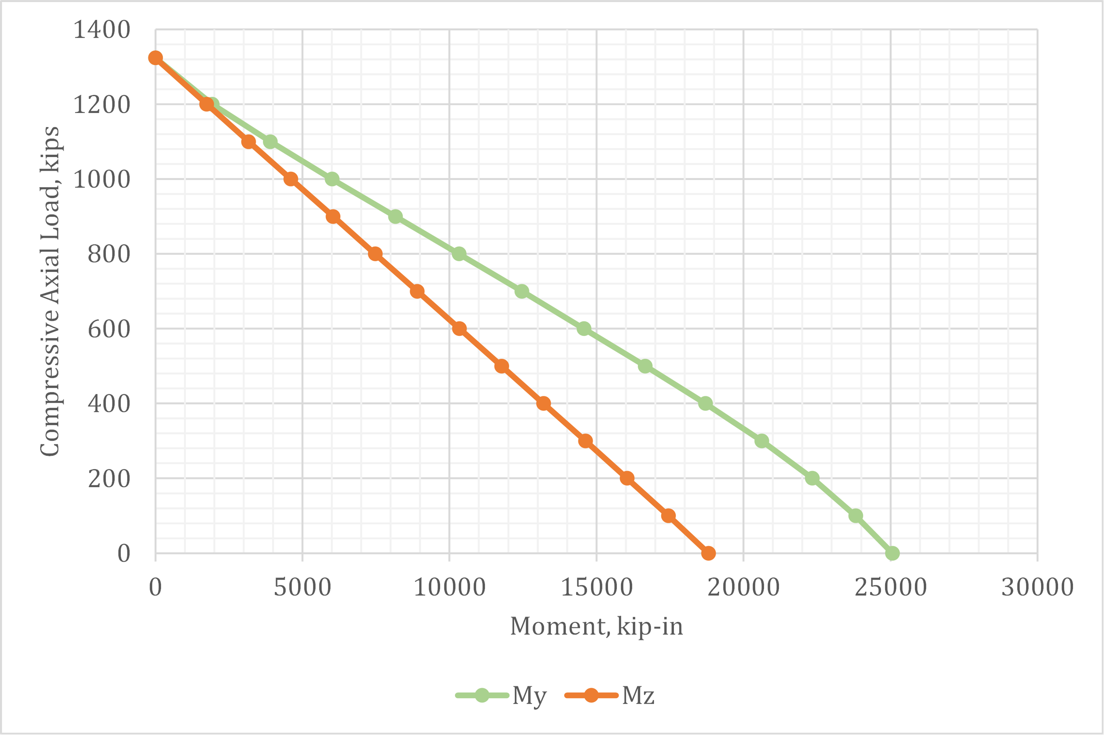
Fig. 8 Axial compression vs. bending moment interaction strength
4 Shear Along The z-axis
Evaluation of the connection when subjected to shear along the z-axis requires a different simplified model of behavior. The two-dimensional beam model shown in Fig. 9 will be used for this evaluation. A hinge, representative of a point of zero moment, is included at mid-height of the strap plates.
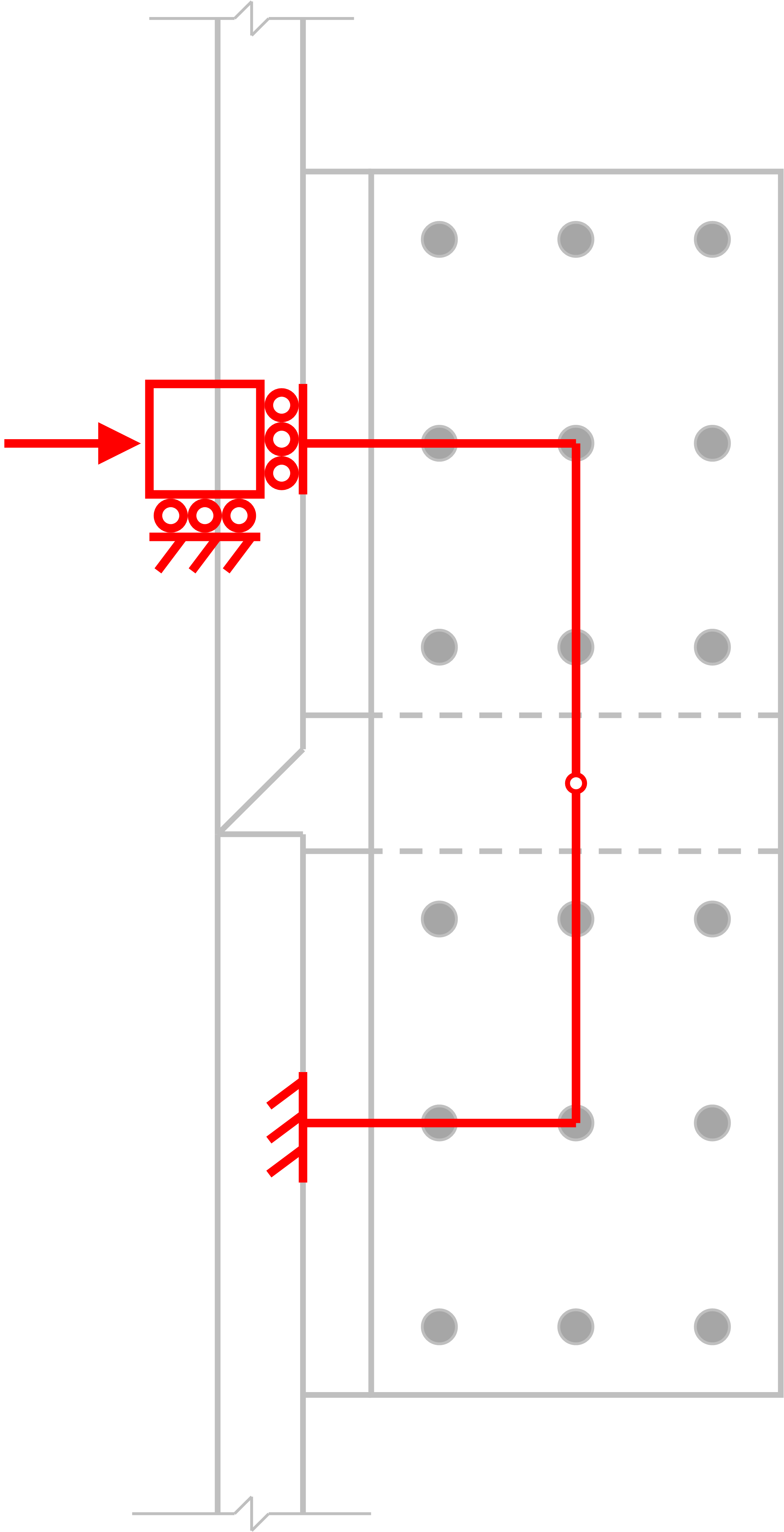
Fig. 9 Simplified model of lug splice connection for shear along the z-axis
As before, when evaluating axial loads, the welds, lug plate material adjacent to the welds, and bolt groups will be evaluated first. The welds can be evaluated using Table 8-5 of the AISC Manual (2017). Using an interpolated value of C, the maximum shear for an individual lug splice is determined as 218 kips.
The strength of the lug plate material adjacent to the welds is controlled by axial and flexural yielding and can be evaluated using the following interaction equation based on plastic stress distribution.
\[ \left ( \frac{P_u}{\phi P_n} \right ) ^2 + \frac{M_u}{\phi M_n} \le 1 \]
where, Pu is the required axial strength of the lug plate, equal to one-fourth of the shear load applied to the upper column; ϕPn is the design axial strength of the lug plate, equal to 720 kips; Mu is the required flexural strength of the lug plate, equal to Pu×(10 in.); and ϕMn is the design flexural strength of the lug plate, equal to 2,880 kip-in. Evaluating the interaction equation for the strength of the weld (i.e., Pu = 218 kips) results in a value less than 1, indicating that the strength of the lug plate material adjacent to the welds does not control.
The strength of the bolt group can be determined using Table 7-11 of the AISC Manual. Using an interpolated value of C, the maximum shear for an individual lug splice is calculated as 186 kips, which controls among the limit states evaluated thus far. To complete the design, other limits states, including tensile rupture of the lug plate and those associated with the strap plates, need to be evaluated for this load. These limit states are found not to control, thus the maximum permitted applied shear along the z-axis of the column is 4×186 kips = 744 kips.
The maximum permitted applied shear load along the z-axis per IDEA StatiCa is 694 kips. This value was determined iteratively as described previously. Note that shear was applied such that the point of zero moment was located between the upper and lower columns. The strength of the bolts controlled in IDEA StatiCa.
As before, the behavior of the connection as observed in the IDEA StatiCa results is consistent with the behavior assumed in the traditional calculations. The deformed shape, plastic strain results, and bolt forces (Fig. 10 and Fig. 11) show in-plane bending of the lug splice connections, weld groups, and bolt groups that is consistent with the simplified model of behavior (Fig. 9). The strength per IDEA StatiCa is 7% lower than estimated by traditional calculations. These results confirm the hypothesis formed by the traditional calculations.
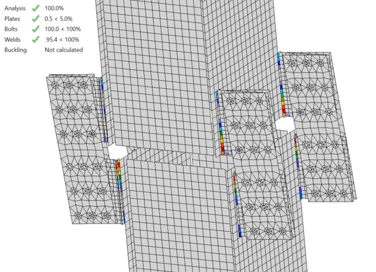
Fig. 10 Plastic stain at 694 kips applied shear along the z-axis (deformation scale factor = 10)
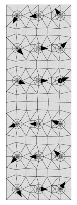
Fig. 11 Bolt forces in strap plate at 694 kips applied shear along the z-axis
5 Shear Along The y-axis
Evaluation of the connection when subjected to shear along the y-axis requires yet another simplified model of behavior. However, this model of behavior is less simple than the others. The beam model shown in Fig. 9 will be used for this evaluation, but with the load applied perpendicular to the lug connection, resulting in out-of-plane moment, out-of-plane shear, and torsion in the lug plate. The AISC Specification (2016) has few provisions for this complex loading condition. Recommendations developed by Dowswell (2019) will be used to gain some feel for the strength of the connection. Dowswell presents the following interaction equation.
\[ \left ( \frac{T_u}{\phi T_n} \right ) ^2 + \left ( \frac{V_u}{\phi V_n} \right ) ^4 + \frac{M_u}{\phi M_n} \le 1 \]
where, Tu, Vu, and Mu are the required torque, shear, and flexural strengths and ϕTn, ϕVn, ϕMn are the design torque, shear, and flexural strengths. Based on the model presented in Fig. 9 and assuming no moment in either direction at the hinge, Vu is equal to one-fourth of the shear load applied to the upper column, Tu = Vu×(10 in.), and Mu = Vu×(8 in.). Assuming ϕ = 0.9, ϕTn can be calculated using equations recommended by Dowswell as
\[ \phi T_n = \phi \left ( \frac{ 0.6 F_y d t^2}{2} \right ) \left ( 1+ \frac{d}{2.4 L} \right ) \]
where, Fy is the yield strength of the lug plate (50 ksi), d is the depth of the lug plate (16 in.), t is the thickness of the lug plate (1 in.), and L is the length of the lug plate (8 in. per the model presented in Fig. 9). Using these values, ϕTn = 396 kip-in. Using standard equations in the AISC Specification (2016), ϕVn = 480 kips and ϕMn = 180 kip-in. With these design strengths, the maximum value of Vu that satisfies the interaction equation is Vu = 17.9 kips. Assuming lug plate yielding controls, the maximum permitted applied shear along the z-axis of the column is 4×17.9 kips = 71.6 kips.
This strength is part of the hypothesis which will be evaluated using IDEA StatiCa results. However, an engineer should have less confidence in this expected strength than those for the other loading conditions. Fewer potentially controlling limit states were evaluated, the out-of-plane behavior of the lug splice connection is likely not well approximated by Fig. 9, and several assumptions were made in computing the strength of the lug plate. Nonetheless, it is helpful to form a hypothesis beforehand. Also, the hypothesis consists of more than just the strength result. The expected behavior, that the lug plate will control and that it will be subjected to combined torsion, out-of-plane shear, and out-of-plane bending moment, is also part of the hypothesis. While explicit modeling of the stiffness and strength of each component will overcome the uncertainties of the traditional calculations and yield a different strength result, the overall behavior should be consistent.
The maximum permitted applied shear load along the y-axis per IDEA StatiCa is 249 kips. This value was determined iteratively as described previously. Note that shear was applied such that the point of zero moment was located between the upper and lower columns. The strength per IDEA StatiCa is significantly greater than that estimated by the traditional calculations. An examination of the deformed shape of the connection (Fig. 12) reveals the cause for this difference. The strap plates are relatively stiff meaning that most of the twist and out-of-plane bending of the lug plates occurs over a much shorter length than is assumed in the simplified beam model of the connection (Fig. 9). Nonetheless, the strength of the connection is controlled by the plastic strain in the lug plate and the types of demands on the lug are consistent with the assumed behavior.
Recalculating the strength of the lug plate using the traditional calculations and a length, L = 2 in. instead of L = 8 in. produces a maximum permitted applied shear along the z-axis of the column equal to 227 kips, which is closer to the IDEA StatiCa results. However, it would be difficult to arrive at this value, let alone be confident in it, a priori.
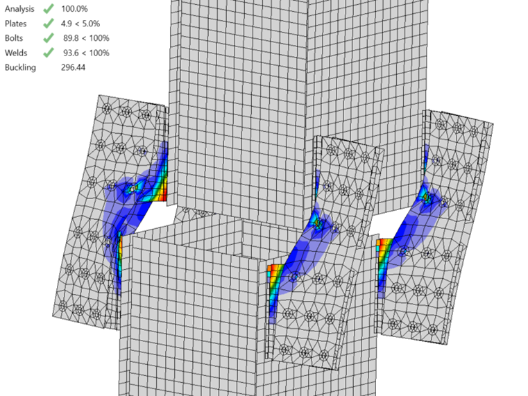
Fig. 12 Plastic stain at 249 kips applied shear along the y-axis (deformation scale factor = 10)
6 Torsion
It is expected that applying torsion to the upper column places demands on each individual lug splice that are similar to those they experience when the upper column is subjected to shear along the y-axis. Thus, like the flexural strength of the connection, the torsion strength could be estimated from the strength of the individual lugs and the geometry of the cross-section. For example, the torsion strength could be estimated as 4 times the strength of each lug times the distance from the centroid of the column to each lug. However, this may be an overly simplistic approximation. The lugs are near the corners of the column and not centered on the faces, thus twist of the column will impart in-plane demands on the lug in addition to the out-of-plane demands. Also, it is unclear where on the lug each lever arm should be measured. It is likely not possible to come to an accurate and confident result on the torsion strength of this connection without a better understanding and characterization of its behavior from more detailed analysis.
The maximum permitted applied torsion per IDEA StatiCa is 9,045 kip-in. This value was determined iteratively as described previously. The weld utilization controls the strength. As seen in Fig. 13, the deformed shape of each lug splice connection is similar when the column is subjected to shear along the y-axis (Fig. 12). However, there are differences in the behavior, most notably weld utilization controlling for the torsion case in lieu of the plastic strain limit in the lug plate controlling for the shear loaded case. While fewer comparisons can be made for this loading condition, the comparisons to other loading conditions have demonstrated that the model is well-defined and capable of providing results that are in line with traditional methods.
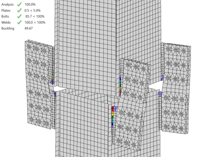
Fig. 13 Plastic stain at 9,045 kip-in. applied torsion (deformation scale factor = 10)
7 Summary
Design or evaluation of structural connections requires good engineering judgment. Good engineering judgment requires understanding how the connection will behave. Developing this understanding is part of the process of evaluating novel connections that do not have established design procedures. In many cases, logical reasoning can be used to develop simplified models of behavior upon which traditional calculations can be based. However, there are limitations to this approach. More advanced tools, such as the CBFEM, are not subject to the same limitations and can be used to better understand and subsequently design a wide range of connection types. But care must be taken when defining the model and performing the analysis to ensure that the results are meaningful. Comparisons to simplified models of behavior and traditional calculations, such as those presented in this study, can help confirm the model is well-defined and the analysis was performed correctly.
8 References
AISC. (2016). Specification for Structural Steel Buildings. American Institute of Steel Construction, Chicago, Illinois.
AISC. (2017). Steel Construction Manual, 15th Edition. American Institute of Steel Construction, Chicago, Illinois.
Dowswell, B. (2019). “Torsion of Rectangular Connection Elements.” Engineering Journal, AISC, 56(2), 63–87.
Drucker, D. C. (1956). “The Effect of Shear on the Plastic Bending of Beams.” Journal of Applied Mechanics, 23(4), 509–514.
Tamboli, A. (2016). Handbook of Structural Steel Connection Design and Details, Third Edition. McGraw Hill, New York, NY.