


Crack width calculation
There are two ways of computing crack widths - stabilized and non-stabilized cracking. According to the geometrical reinforcement ratio in each part of the structure is decided, which type of crack calculation model will be used (TCM for stabilized cracking and POM for non-stabilized cracking model).

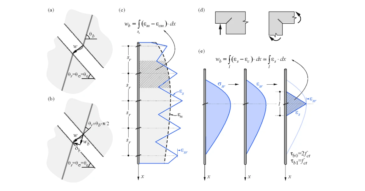
While the CSFM yields a direct result for most verifications (e.g., member capacity, deflections…), crack width results are calculated from the reinforcement strain results directly provided by FE analysis following the methodology described in Fig. 20. A crack kinematic without slip (pure crack opening) is considered (Fig. 20a), which is consistent with the main assumptions of the model. The principal directions of stresses and strains define the inclination of the cracks (θr = θs= θe). According to (Fig. 20b), the crack width (w) can be projected in the direction of the reinforcing bar (wb), leading to:
where θb is the bar inclination.
Please note, that the program displays values of θr and θb < π/2. It means that the previous equation works for cases, where the reinforcement and crack go through the different quadrants of the Cartesian coordinate system as shown in Fig. 20, where reinforcement goes through I. and III. quadrants and crack through II and IV. For cases where the reinforcement and crack go through the same quadrants, the equation has to be modified as follows:
The component wb is consistently calculated based on the tension stiffening models by integrating the reinforcement strains. For those regions with fully developed crack patterns, the calculated average strains (em) along the reinforcing bars are directly integrated along the crack spacing (sr), as indicated in (Fig. 20c). While this approach to calculating the crack directions does not correspond to the real position of the cracks, it still provides representative values that lead to crack width results that can be compared to code-required crack width values at the position of the reinforcing bar.
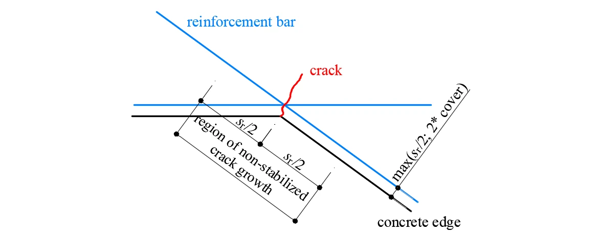
Special situations are observed at concave corners of the calculated structure. In this case, the corner predefines the position of a single crack that behaves in a non-stabilized fashion before additional adjacent cracks develop. These additional cracks generally develop after the serviceability range (Mata-Falcón 2015), which justifies calculating the crack widths in such a region as if they were non-stabilized (Fig. 21).
Tension stiffening
The implementation of tension stiffening distinguishes between cases of stabilized and non-stabilized crack patterns. In both cases, the concrete is considered fully cracked before loading by default.

Stabilized cracking
In fully developed crack patterns, tension stiffening is introduced using the Tension Chord Model (TCM) (Marti et al. 1998; Alvarez 1998) – Fig. 22a – which has been shown to yield excellent response predictions in spite of its simplicity (Burns 2012). The TCM assumes a stepped, rigid-perfectly plastic bond shear stress-slip relationship with τb = τb0 =2 fctm for σs ≤ fy and τb =τb1 = fctm for σs > fy. Treating every reinforcing bar as a tension chord – Fig. 22b and Fig. 22a – the distribution of bond shear, steel, and concrete stresses and hence the strain distribution between two cracks can be determined for any given value of the maximum steel stresses (or strains) at the cracks.
For sr = sr0, a new crack may or may not form because at the center between two cracks σc1 = fct. Consequently, the crack spacing may vary by a factor of two, i.e., sr = λsr0, with l = 0.5…1.0. Assuming a certain value for λ, the average strain of the chord (εm) can be expressed as a function of the maximum reinforcement stresses (i.e., stresses at the cracks, σsr). For the idealized bilinear stress-strain diagram for the reinforcing bare bars considered by default in the CSFM, the following closed-form analytical expressions are obtained (Marti et al. 1998):
where:
Esh the steel hardening modulus Esh = (ft – fy)/(εu – fy /Es) ,
Es modulus of elasticity of reinforcement,
Ø reinforcing bar diameter,
sr crack spacing,
σsr reinforcement stresses at the cracks,
σs actual reinforcement stresses,
fy yield strength of reinforcement.
The Idea StatiCa Detail implementation of the CSFM considers average crack spacing by default when performing computer-aided stress field analysis. The average crack spacing is considered to be 2/3 of the maximum crack spacing (λ = 0.67), which follows recommendations made on the basis of bending and tension tests (Broms 1965; Beeby 1979; Meier 1983). It should be noted that calculations of crack widths consider a maximum crack spacing (λ = 1.0) in order to obtain conservative values.
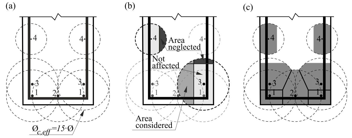
The application of the TCM depends on the reinforcement ratio, and hence the assignment of an appropriate concrete area acting in tension between the cracks to each reinforcing bar is crucial. An automatic numerical procedure has been developed to define the corresponding effective reinforcement ratio (ρeff = As/Ac,eff) for any configuration, including skewed reinforcement (Fig. 23).
Non-stabilized cracking
Cracks existing in regions with geometric reinforcement ratios lower than ρcr, i.e., the minimum reinforcement amount for which the reinforcement is able to carry the cracking load without yielding, are generated by either non-mechanical actions (e.g. shrinkage) or the progression of cracks controlled by other reinforcement. The value of this minimum reinforcement is obtained as follows:
where:
fy reinforcement yield strength,
fct concrete tensile strength,
n modular ratio, n = Es / Ec .
For conventional concrete and reinforcing steel, ρcr amounts to approximately 0.6%.
For stirrups with reinforcement ratios below ρcr, cracking is considered to be non-stabilized and tension stiffening is implemented by means of the Pull-Out Model (POM) described in Fig. 22b. This model analyzes the behavior of a single crack considering no mechanical interaction between separate cracks, neglecting the deformability of concrete in tension and assuming the same stepped, rigid-perfectly plastic bond shear stress-slip relationship used by the TCM. This allows the reinforcement strain distribution (εs) in the vicinity of the crack to be obtained for any maximum steel stress at the crack (σsr) directly from equilibrium. Given the fact that the crack spacing is unknown for a non-fully developed crack pattern, the average strain (εm) is computed for any load level over the distance between points with zero slip when the reinforcing bar reaches its tensile strength (ft) at the crack (lε,avg in Fig. 22b), leading to the following relationships:

The proposed models allow the computation of the behavior of bonded reinforcement, which is finally considered in the analysis. This behavior (including tension stiffening) for the most common European reinforcing steel (B500B, with ft / fy = 1.08 and εu = 5%) is illustrated in Fig. 22c-d.