Reinforcement in RCS application
There are several options for the reinforcement setup for a 1D cross-section:
- Templates
- Import
- Reinforcement editor
For information about the reinforcement setup for 2D elements, check out the Reinforcement for 2D elements article!
Now, let's see the options:
Templates
As well as for geometry, the RCS application offers pre-defined templates for reinforcement. This option is available only for cross-sections created by pre-defined templates.
Setting a template
To set the reinforcement, go to Navigator -> Reinforcement, and select a preferred template in the top ribbon. The layout table will appear, so just fill in the values, and click OK.
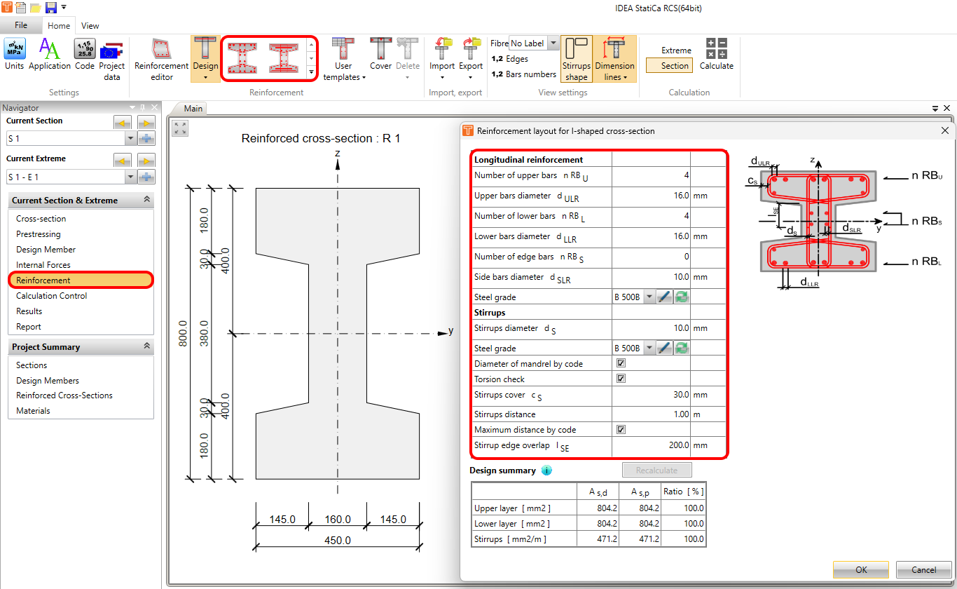
After that, you will see the tables of reinforcement bars and reinforcement layers in the Data window. Working with the tables, you can adjust properties such as the diameter, number of layers, if the reinforcement is bent-up, and reinforcement type (this functionality is meant for Fatigue calculation).
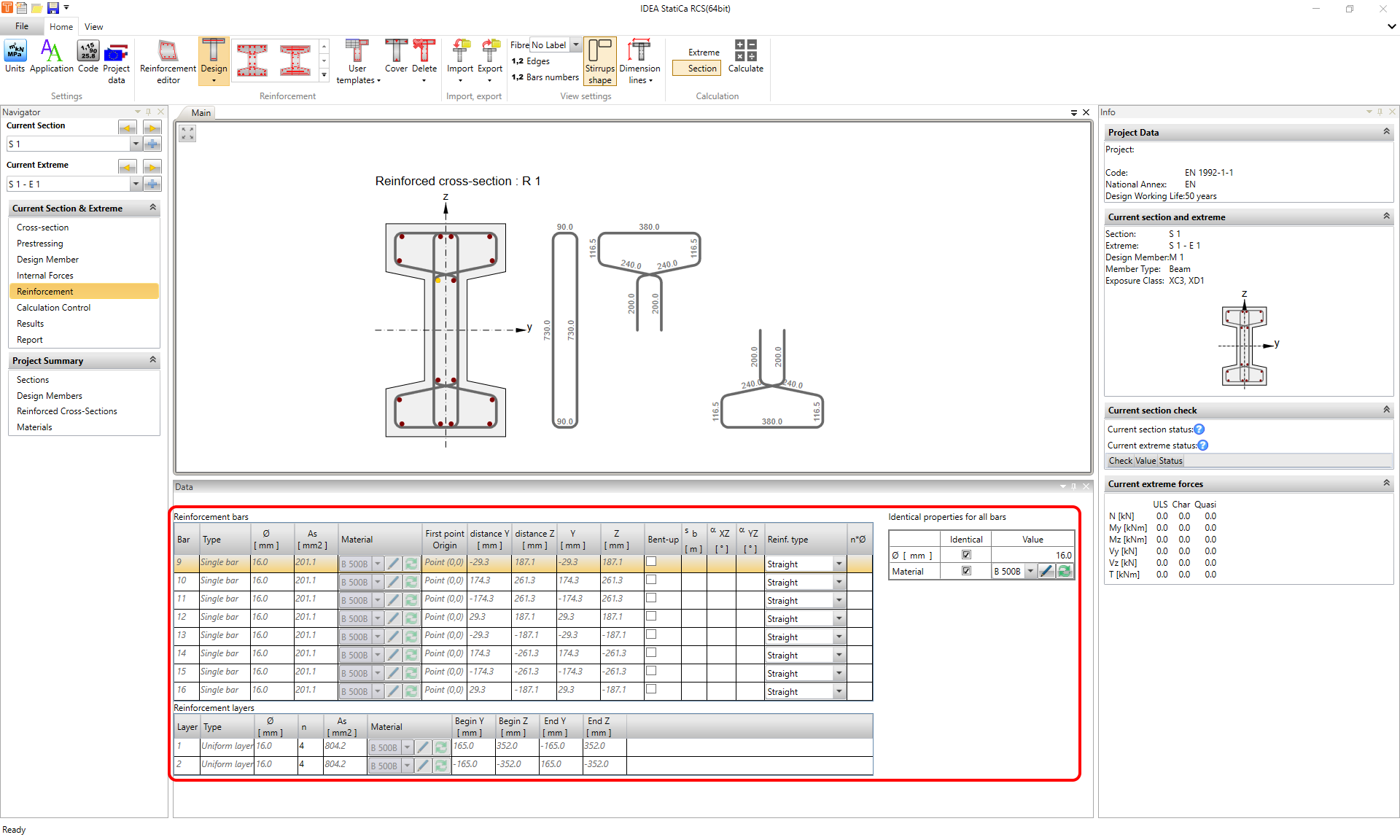
The reinforcement's diameter and material can be set individually for each bar. In case of having the same diameter or material for a group of bars, you can tick the Identical checkboxes and save time setting the properties of bars one by one.
Stirrups modification
Click on the stirrup in the Main graphic window. The selected stirrup is highlighted, and you can see a table with properties in the Data window. Here you can set the diameter, material, spacing, and other settings depending on the stirrup type.
The Shear and Torsion checkboxes in the middle of the table are an important part of this section. Select the corresponding options to choose the type of code-check of the stirrup.
More information about shear and torsion checks, as well as other types of checks, with a thorough description, can be found in the ULS results in RCS - Capacity N-M-M, Shear, Torsion, Interaction, Response N-M-M article.
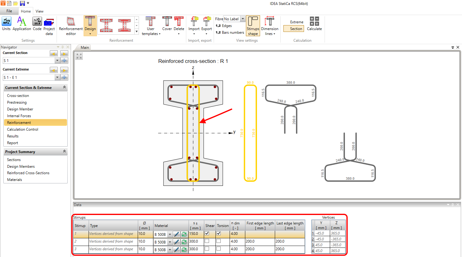
The Stirrups shape can be displayed in the Main graphic window by using the button of the same name in the top ribbon in the View settings section.
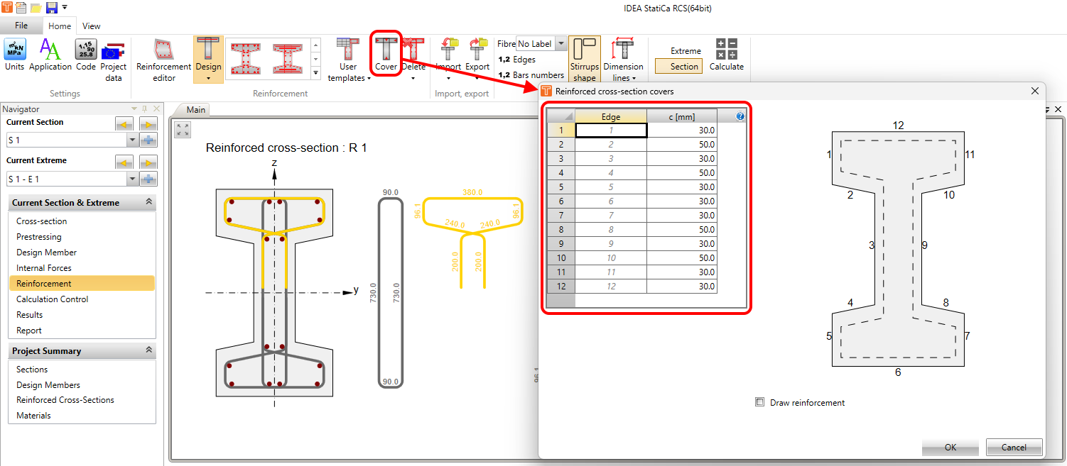
The concrete cover can be set using the Cover button in the top ribbon. It can be set for each edge of the cross-section separately. I.e., each edge can have a different value of concrete cover.
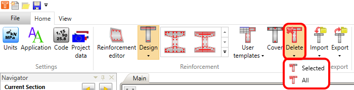
The reinforcement can be deleted using the Delete button in the top ribbon. You can either delete just the selected reinforcement or the whole layout.
Import
To import a file containing reinforcement, click on the Import button in the top ribbon and choose what you want to import. Export (using the button right next to the Import one) works exactly the same way.
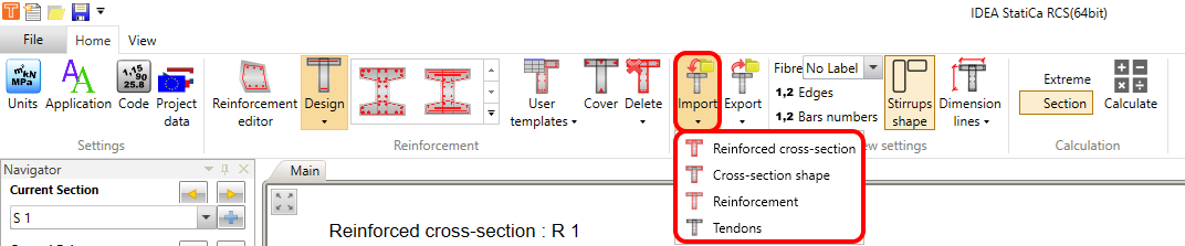
You can export/import cross-section geometry, reinforcement, and tendons separately. Or there is an option to export/import all at once.
Reinforcement editor
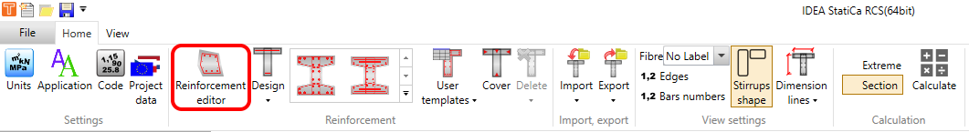
The Reinforcement editor can be very helpful. It is a tool providing you with many possibilities of how to reinforce a cross-section in the RCS application. To launch the editor, click on the Reinforcement editor button in the top ribbon.
A separate window will appear. In the editor, you can, among other things, define reinforcement by templates as well as was shown before. Or you can Import/Export reinforcement. The same applies to deleting. All buttons needed for mentioned operations are in the top ribbon.
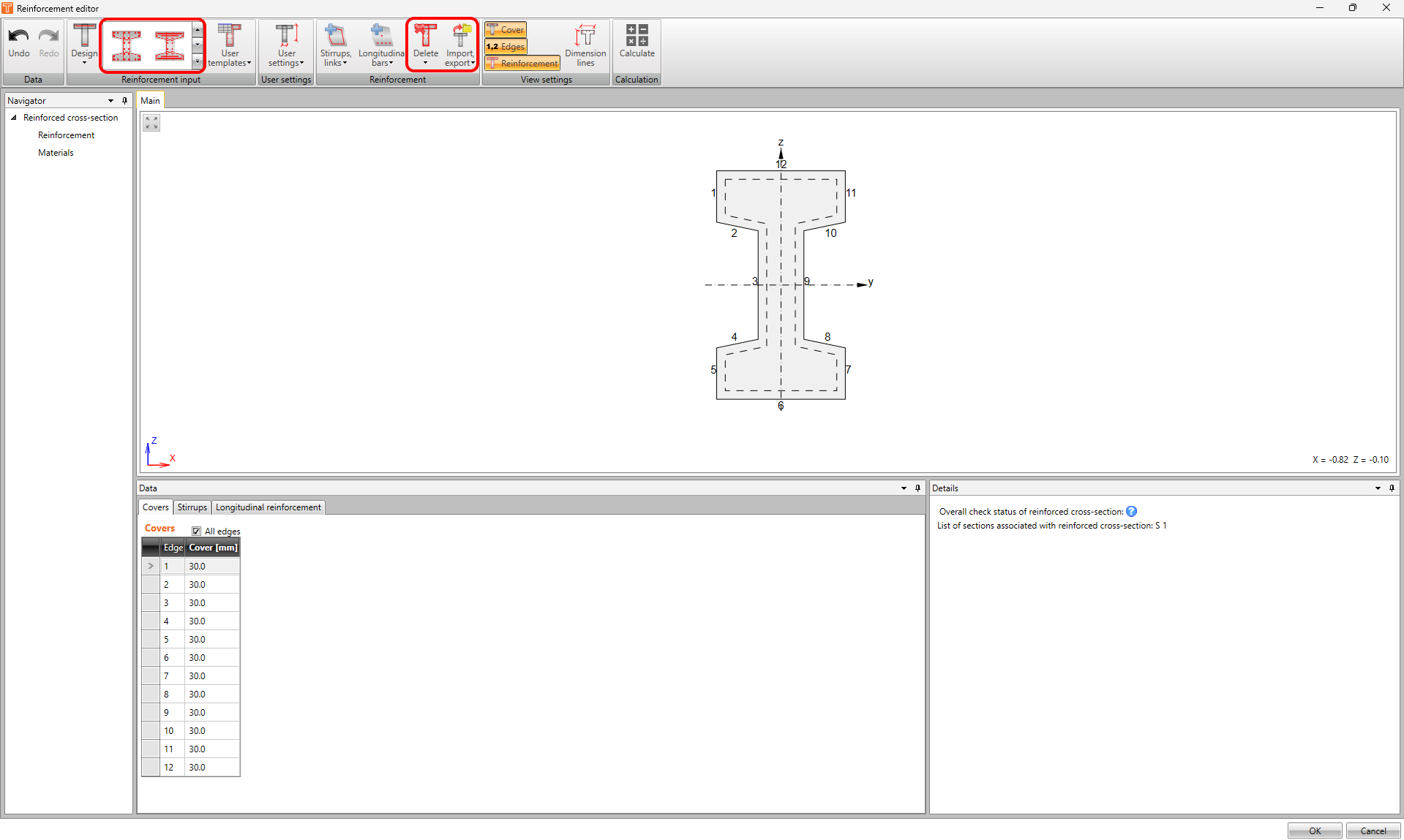
One of the biggest advantages of the editor is the possibility to use Undo and Redo buttons. This cannot be done in the general RCS window.
But that's not all! Let's have a look at what more can be done in the editor, one option by one.
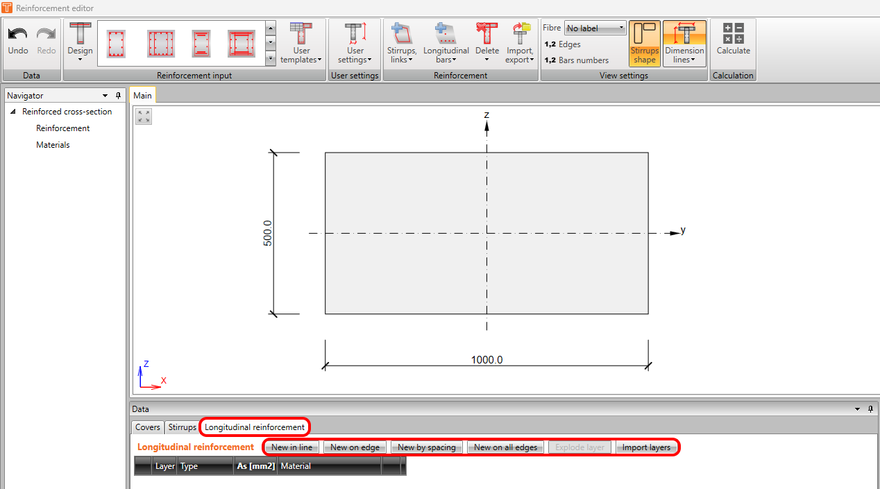
Longitudinal reinforcement
We shall start with defining the longitudinal bars. You can find it in the Data window under the Longitudinal reinforcement tab. There are five possible options available to define reinforcement.
- New in line
- New on edge
- New by spacing
- New on all edges
- Import layers
New in line
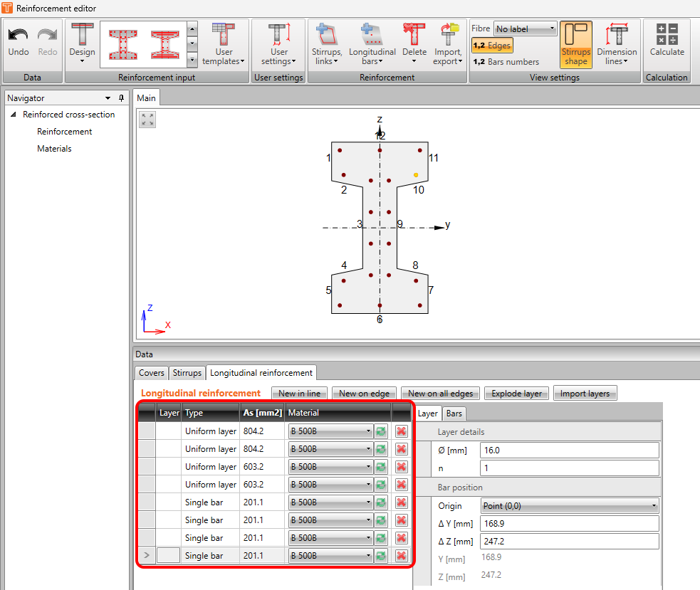
The New in line option defines reinforcement based on coordinates. You have to define the origin of the first bar's position and the last bar's position, which can be Point (0,0) or one of the vertexes. And then, you have to define the delta coordinates of these two points.
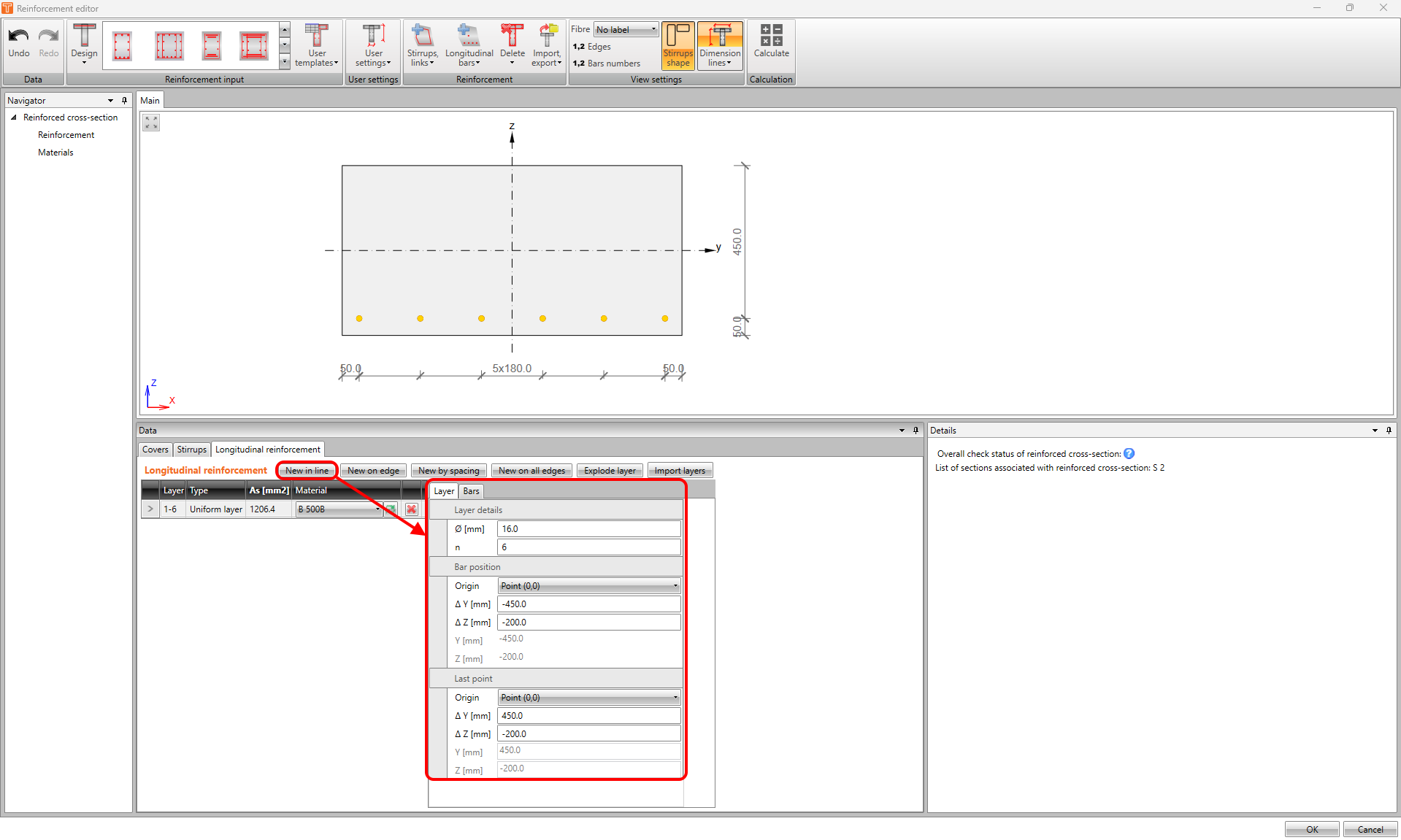
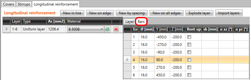
In the Bars tab of the corresponding layer, you can display the position of each bar.
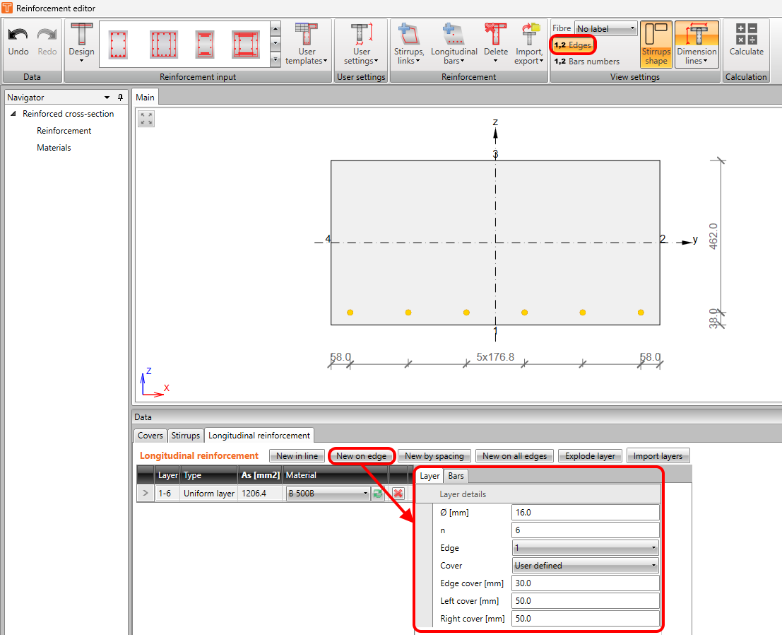
New on edge
The New on edge option defines reinforcement based on the edge number and the cover. The cover can be as defined in the cross-section or user-defined. Don't forget to turn on the labelling of cross-section edges in the top ribbon.
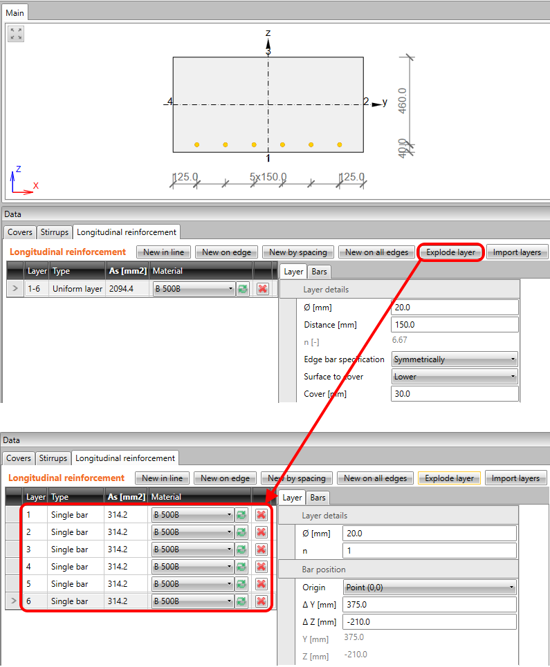
New by spacing
The New by spacing option defines reinforcement based on the distance and cover. The number of bars in the layer is automatically calculated. This option is available only for 1D decks -> for Beam member type only rectangular cross-section and for One-way slab member type.
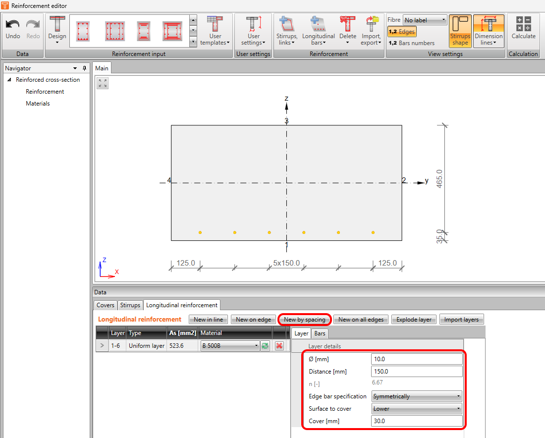
Note that number of bars doesn't have to be an integer number. You can also define surface to cover - lower or upper and edge bar specification - symmetrically, diameter/2, or user-defined.
New on all edges
The New on all edges option defines reinforcement based on the distance and cover.
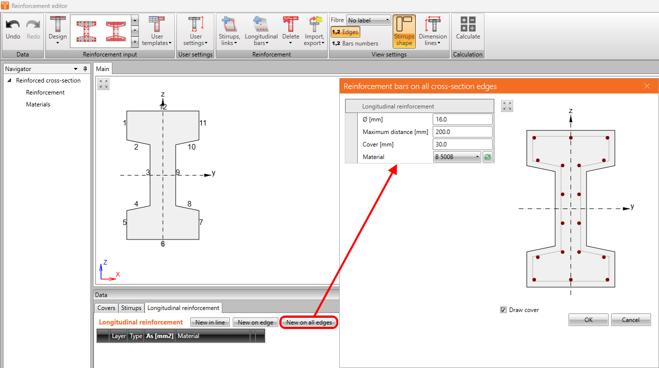
Once you input reinforcement like this the application will create uniform layers or single bars around the cross-section automatically.
Explore layer
All of the previous inputting functionalities create a layer or row of reinforcement bars. To change the position or diameter of a single bar, you can explode the layer and do the modifications only for the selected item.
Import layers
This is the same import functionality which was described above. The only difference is that by this button only the longitudinal reinforcement will be imported.
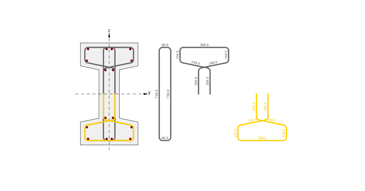
Bent-up bars
You can select which bar will be bent-up in the Bars tab. It can be done for all types of reinforcement. And also as was described above you can select individual bars to be bent-up in the general RCS window.
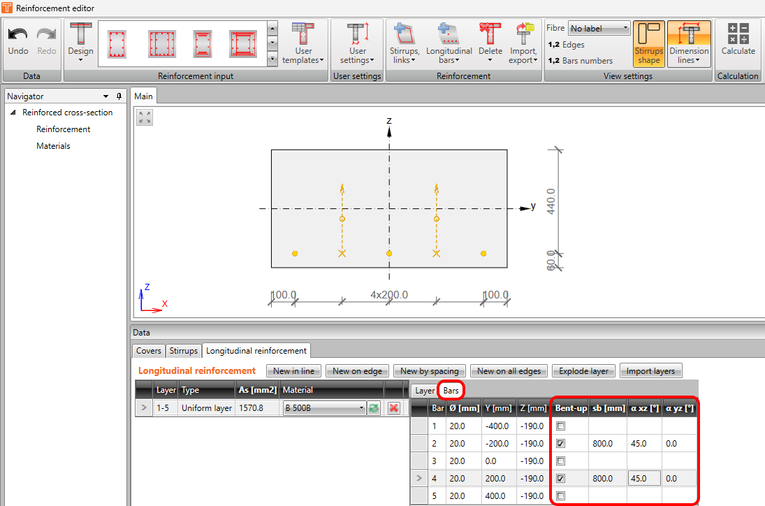
It is necessary to set the values of sb and α correctly. The distance sb is defined as a projection of the inclined part to the direction of beam axis (or a rather effective length of bent-up bar). For more layers of bent-up bars, the distance sb is defined as a horizontal distance between them. After this input, the automatic detection of effective bars in a projection of crack to the axis perpendicular to the geometry of bent-up bars is performed (blue dash-dotted line).
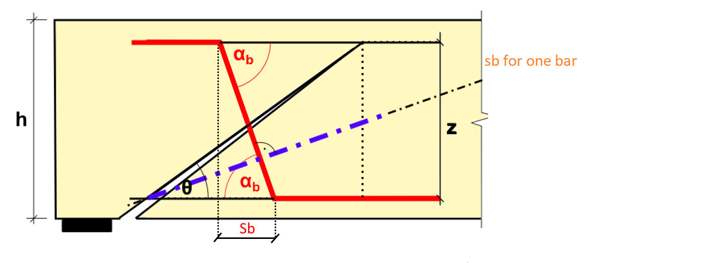
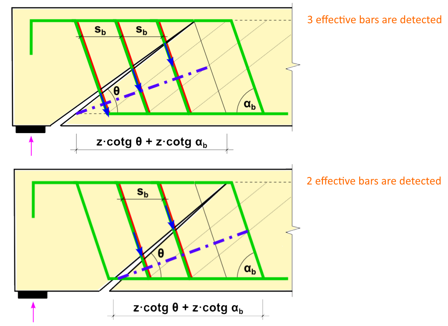
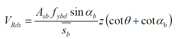
The shear resistance of bent-up bars is defined by the following equation. If we use the unequal distance between the layers of bent-up bars, distance sb is averaged and used in the same equation.
To consider smaller effectiveness of bent-up bars in areas of smaller crack width, there is an option to use the reduction by kb factor. The recommended value is 0,75 (generally <1).
We should also check the maximal distance between bent-up bars according to the code.
sb,max = 0,6 d (1 + cot α) (9.7N)
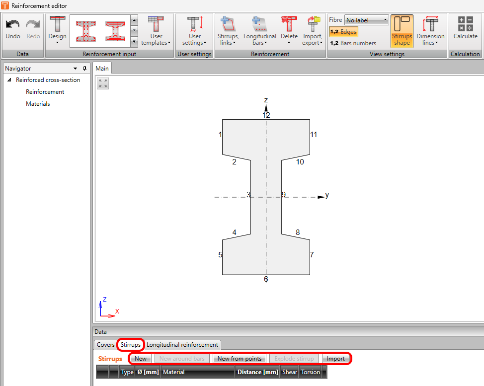
Stirrups
To define stirrups go to the Data window -> Stirrups tab. There are four possible options available to define stirrups.
- New
- New around bars
- New from points
- Import
New
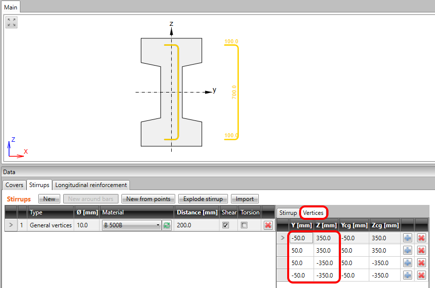
The New option defines stirrups based on coordinates. First, you need to define the origin as a Point (0,0) or as one of the vertexes in the Stirrup tab.
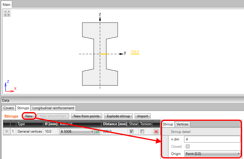
And then you are supposed to define the coordinates in the vertices tab.
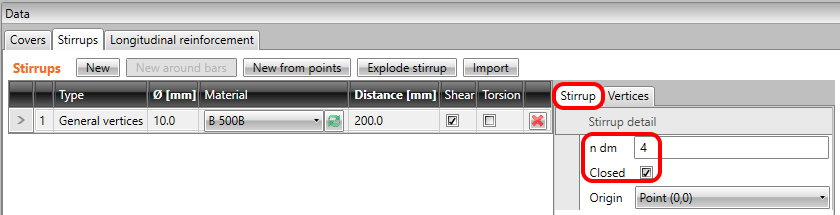
Finally, you can go back to the stirrup tab and check closed if it is needed. Or change the inner diameter of the mandrel ndm which is defined as a multiple of the stirrup diameter.
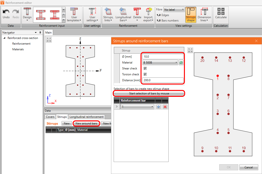
New around bars
The New around bars option defines stirrups based on the reinforcement bars position. Click on the button, set the diameter and distance and click on Start selection of bars by mouse.
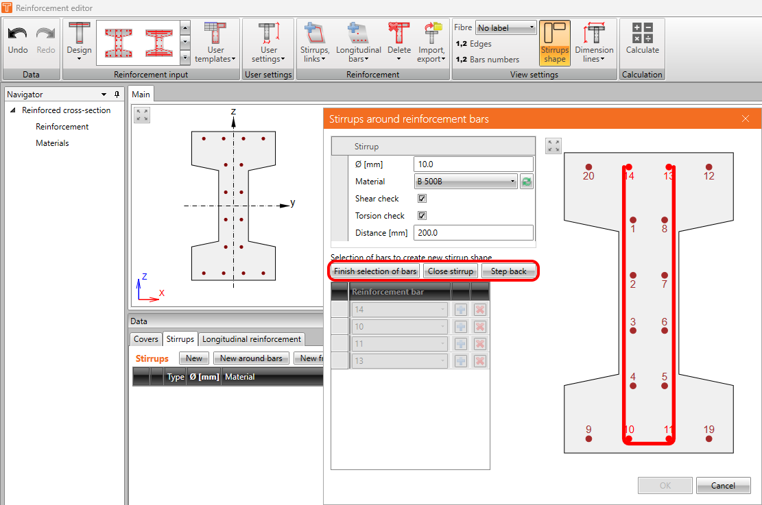
Then gradually select bars. You can use the step back button or finish selection without closing stirrups.
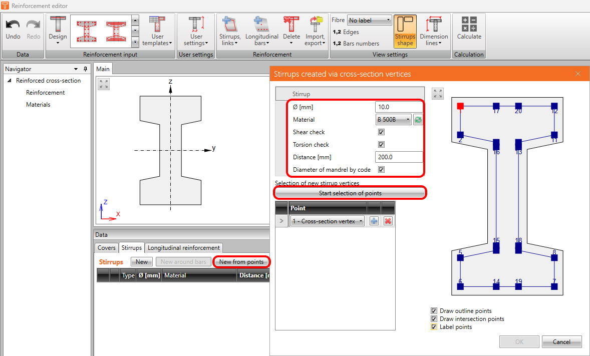
New from points
The New from points option defines stirrups based on the cross-section vertices. Click on the button, set the diameter and distance and click on Start selection of points.
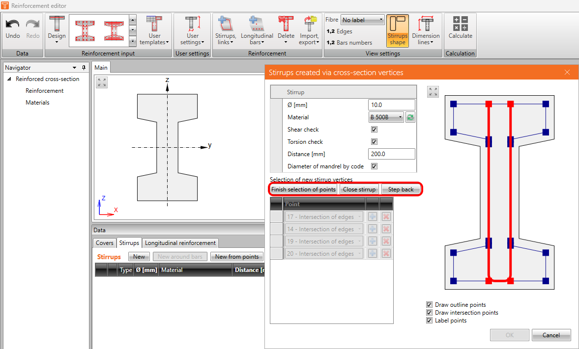
Then gradually select points. You can use the step back button or finish selection without closing stirrups.
Explode stirrup
With this functionality, you can convert stirrup created from points or around bars to the general one defined by coordinates. The converted stirrup will be the same as the stirrup created using the New option.
Import
This is the same import functionality which was described above. The only difference is that by this button only the stirrups will be imported.
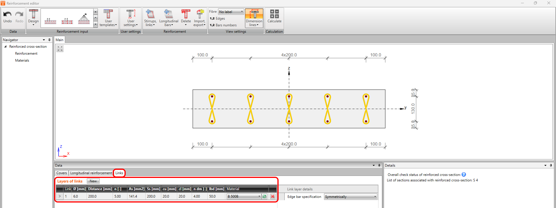
Links
For one-way slabs and for 2D elements, you can define links.
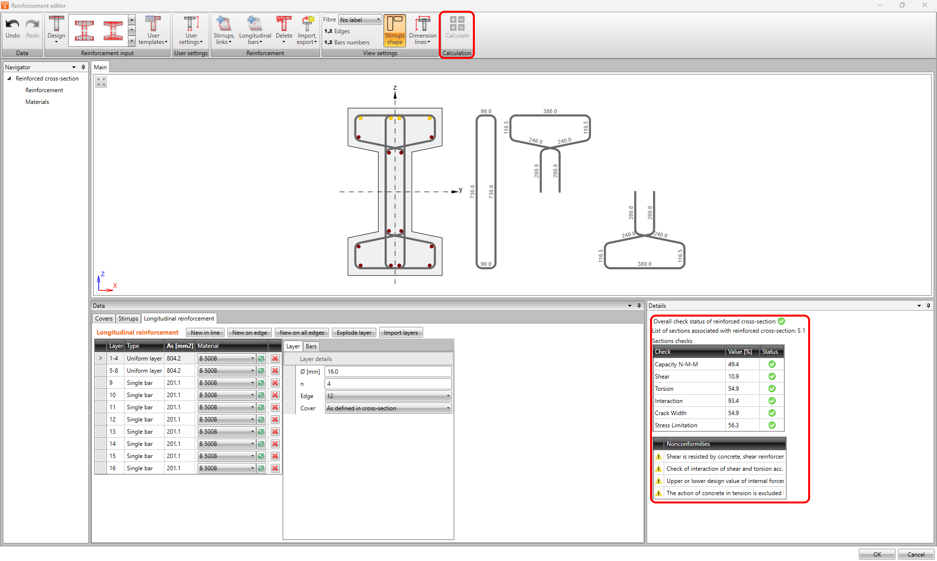
Calculation
In the reinforcement editor, users usually iterate from version to version of the reinforcement design. A useful feature is to calculate the cross-section directly in the editor. There is the calculate button on the top ribbon. After calculation, you will see the overall check status of the reinforced cross-section. And also all of the relevant nonconformities will be available.