Prestressed bridge diaphragm (EN)
1 New project
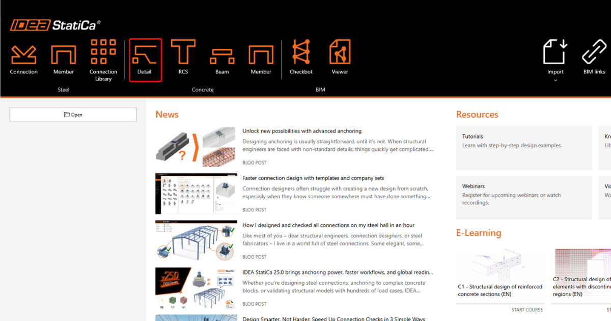
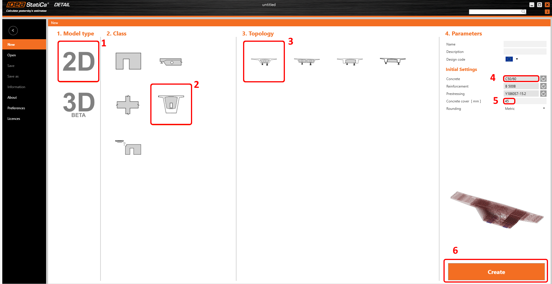
Start the IDEA StatiCa program and select the Detail module
The Wizard window is automatically opened, and you can select 2D Model type, then pick Diaphragms in Class and Box girder diaphragm Topology. You can then continue with a selection of proper concrete grade and cover.
2 Geometry
Start the definition of geometry. Four items have been already created by the template: Diaphragm D1, Opening O1 and Distributed points DPS1 and DPS2.
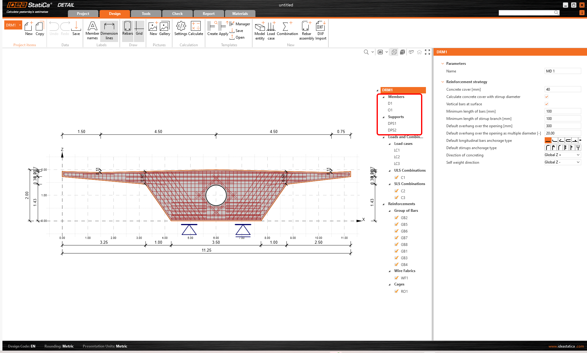
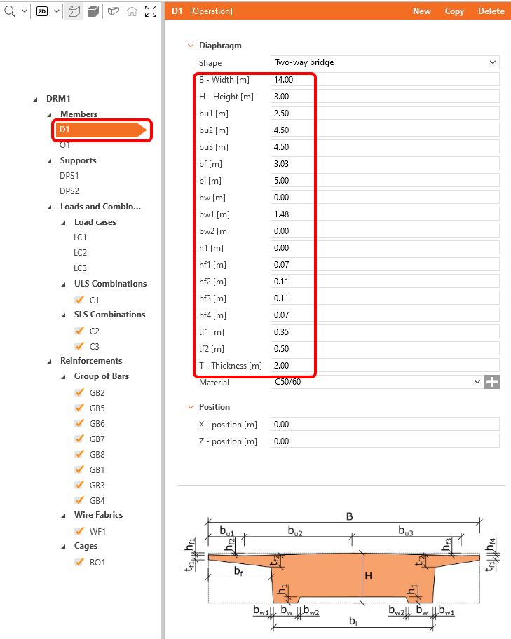
Change geometry of the Diaphragm.
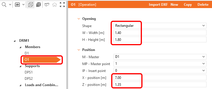
Let's move on to the next item, Opening O1.
Finally, the location and dimensions of the Distributed Point Supports need to be changed. The type of supports is chosen to include the effect of the Partially Loaded Area.

The geometry is set and you can move on to the load definition.
3 Loads
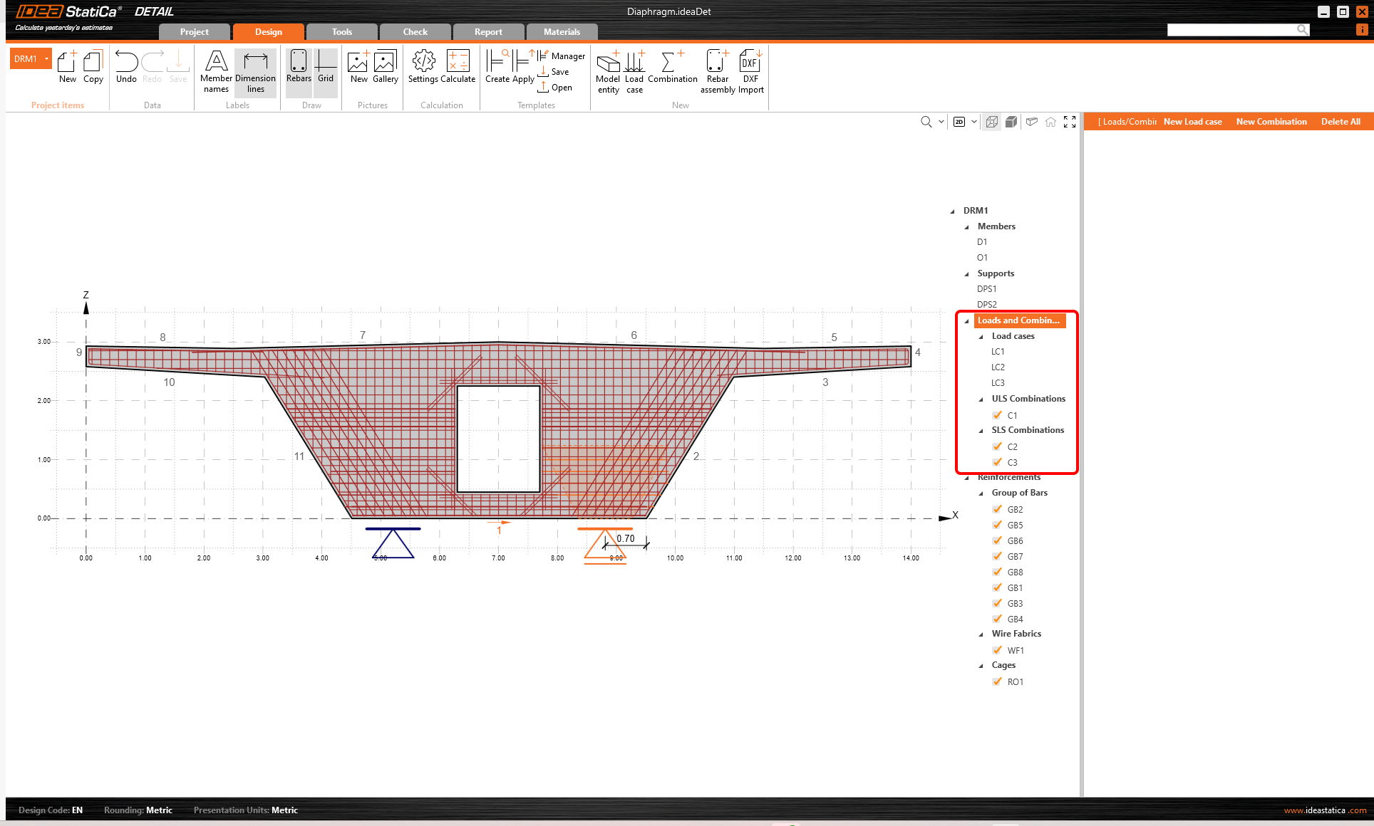
Three load cases and three combinations were automatically created from the template. To properly distinguish between short-term and long-term effects, the Permanent and Variable load states must be set correctly. These settings have a major impact on ULS and SLS checks.
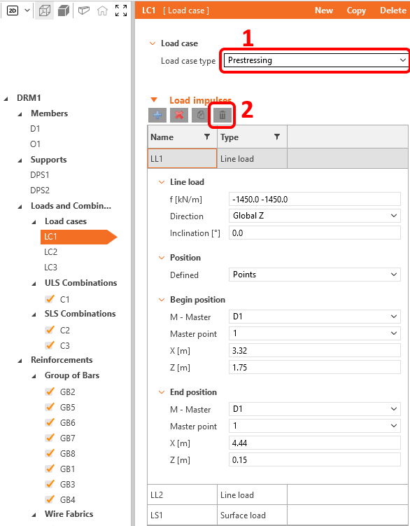
The first thing to do is to set the load case LC1 as a Prestress type. This case will be used later for the transverse prestress. After that, delete all loads from the LC1 load case. Load case LC1 will remain empty for now.
Switch to the load case LC2 and redefine the Line Loads LL3 and LL4. Load case LC2 represents the shear load on the diaphragm from a permanent load. In the example we will not consider shear loading from longitudinal prestressing.
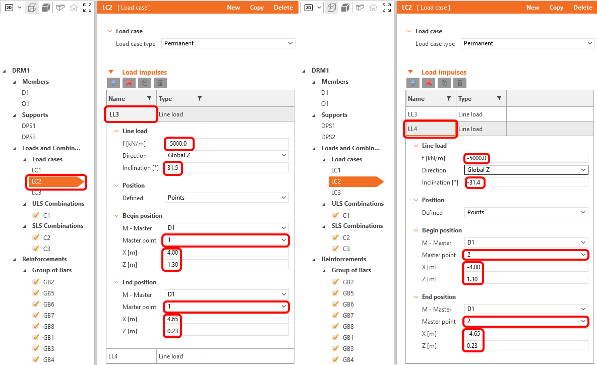
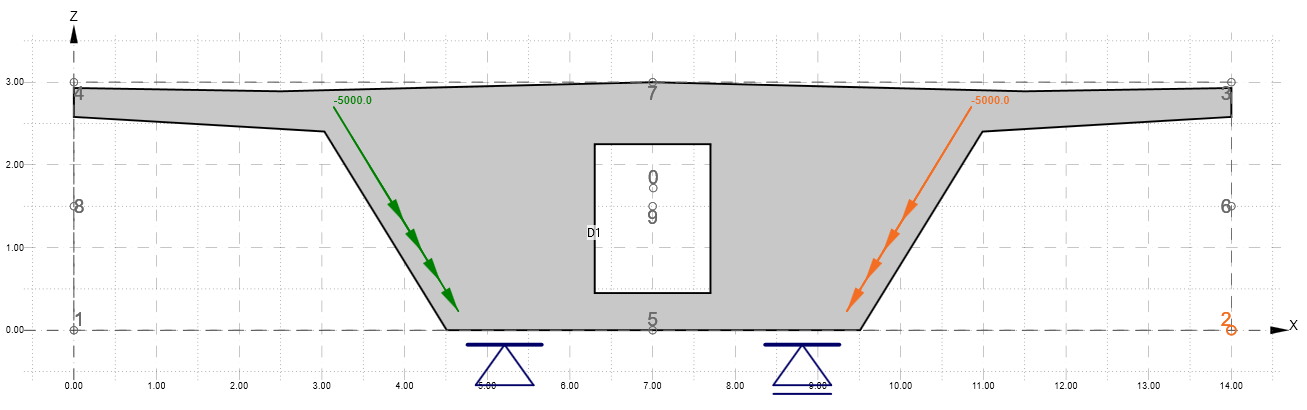
The load case LC2 should look like this:
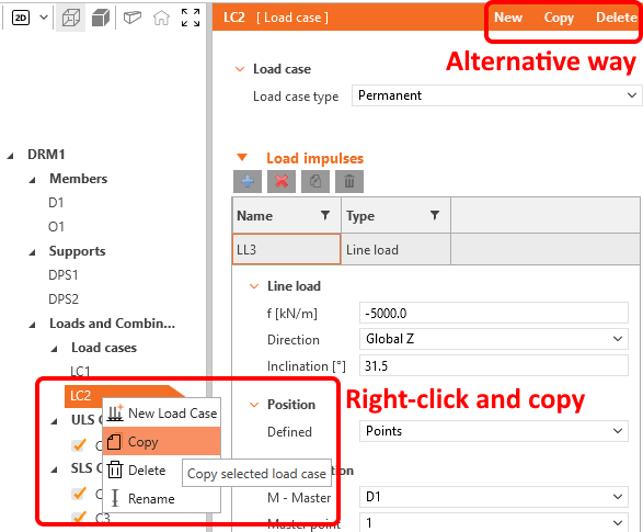
Delete load case LC3 by right-clicking it in the Tree menu and selecting delete in the pop-up menu, then select load case LC2 and copy it using the same procedure. Alternatively you can use the icons at the top of the Properties window.
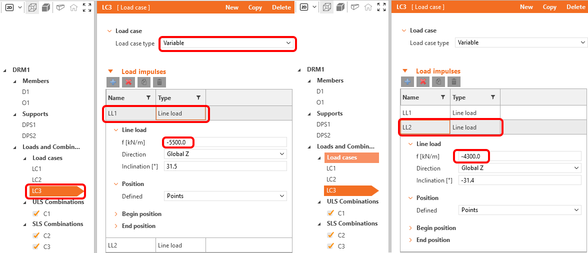
Don't forget to change the type of load case LC3 to Variable. Load case LC3 represents the shear and torsional load from variable loads.
In the Property Window, redefine Line Loads LL1 and LL2 as shown in the figures.
The next step will be to copy the LL2 Line Load. This is done by selecting the appropriate load and clicking on the Copy button. The copied item still needs to be edited.
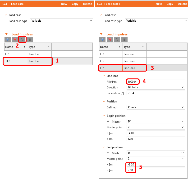
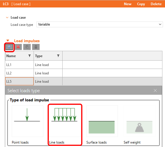
Finally, create 2 new Line loads using the plus button.
Modify the newly created loads.
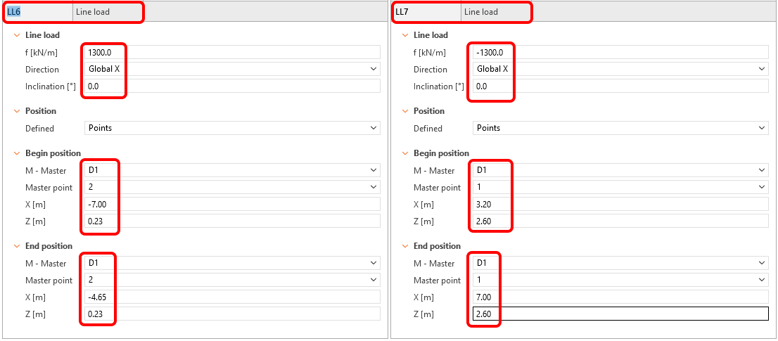
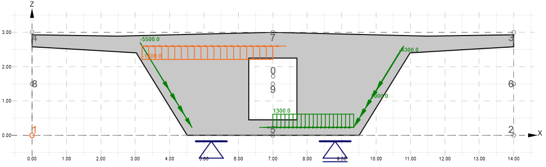
The load case LC3 should be as follows.
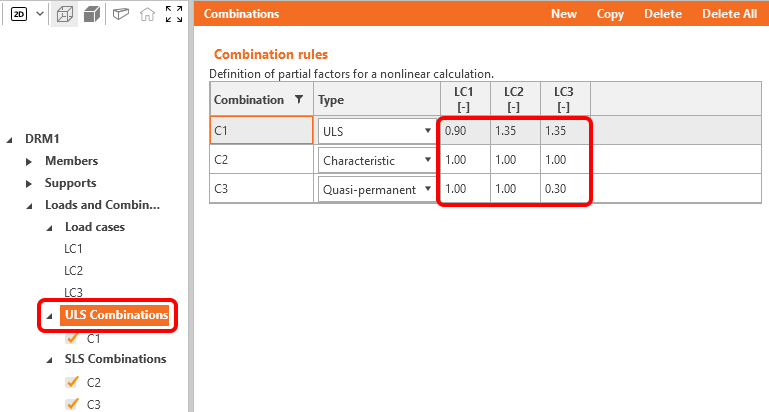
The last adjustment will be the setting of the combination coefficients. To reconfigure the combinations, click on SLS or ULS Combinations, the combination coefficients will be displayed in the property window. Adjust the values as shown. For the load case LC1, we set a value of 0.90 to simulate the long-term losses of transverse prestress.
Currently all load combinations are activated for checks. By disabling some of the combinations for checks, you can achieve a faster calculation, if needed.
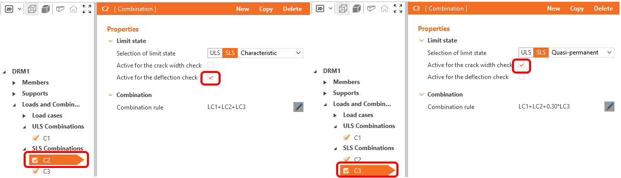
You can define new combinations if required, there are three types of combinations available for SLS code checks: characteristic, frequent and quasi-permanent. You can select which checks shall be performed for each combination. In our case we select the deflection check for C2 and the crack width check for C3.
Loads and combinations are specified. Now we move on to the definition of the reinforcement.
4 Reinforcement
Before we start modifying the reinforcement that was generated by the template, let's take a look at the Topology Optimization that can be found in the Design Tab. The calculation uses an effective volume (in this case, for example, 40%) and places this volume to make the generated structure as stiff as possible.
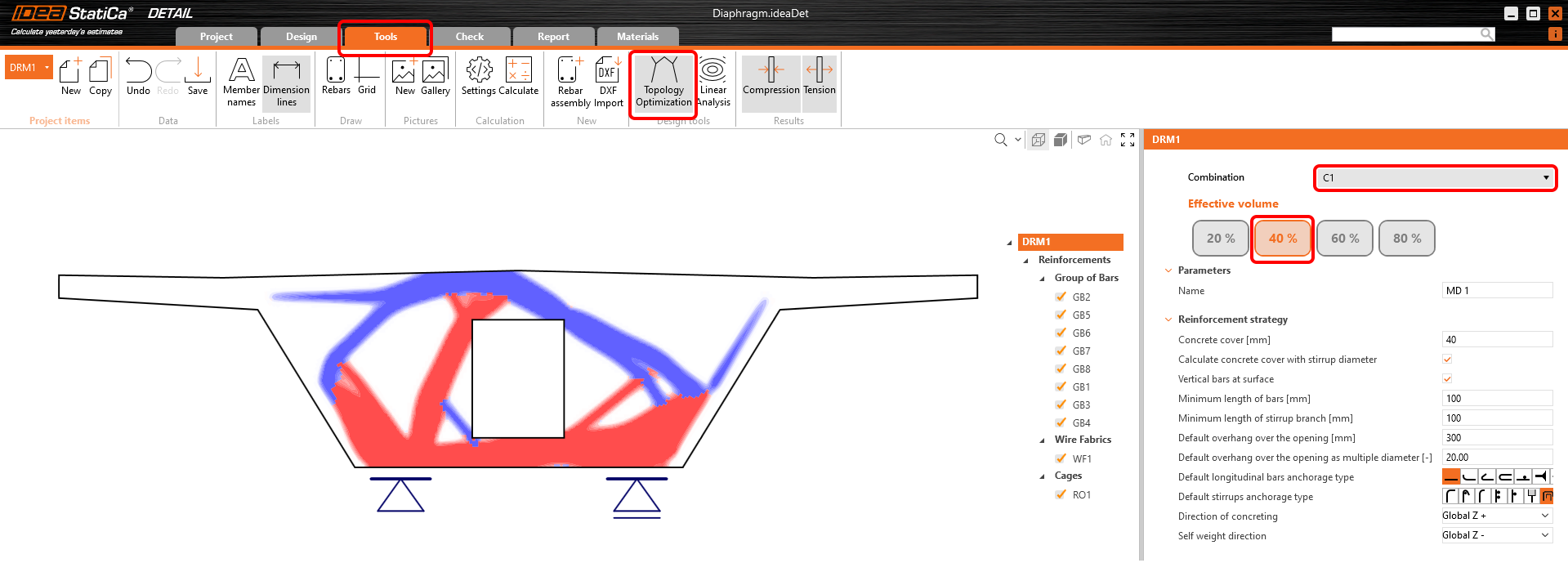
Red areas represent pressure fields and blue areas are tensile.
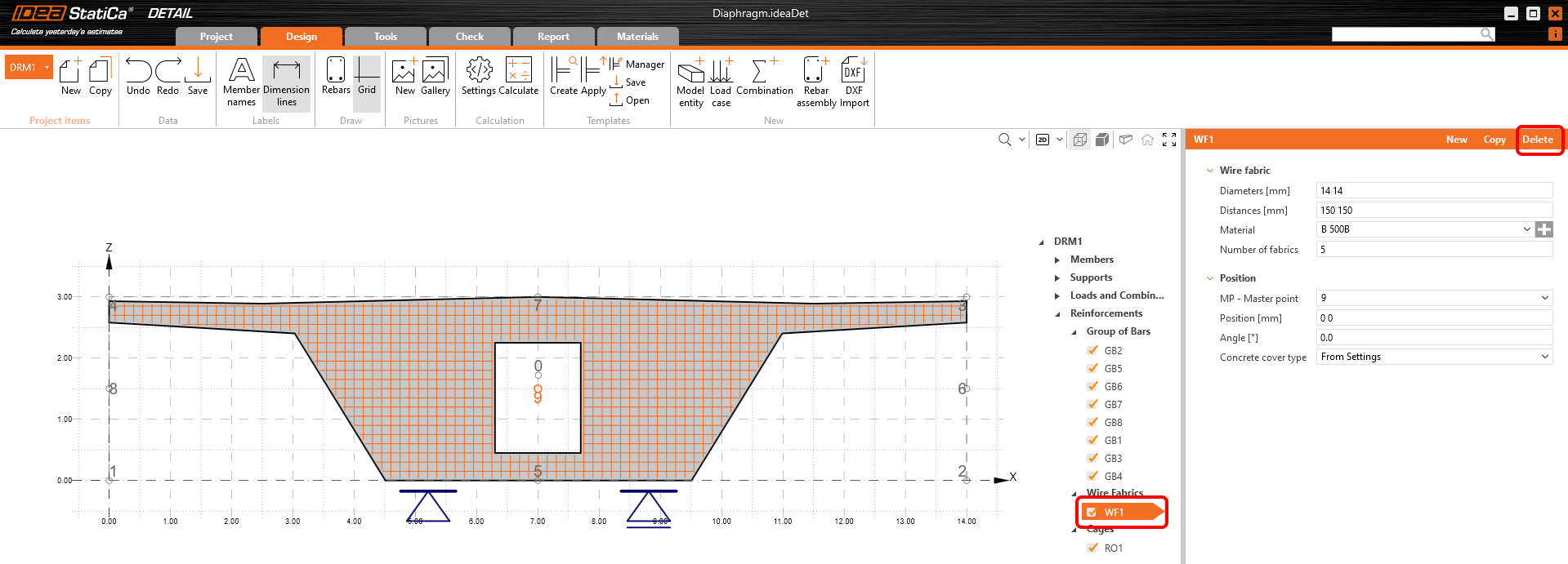
Now, let's reinforce our diaphragm. One Wire fabric, one Cage and eight groups of bars were already added by the template, you will only adjust them to your needs.
At first, delete the Wire fabric WF1.
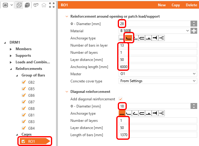
Modify the Reinforcement around opening RO1.
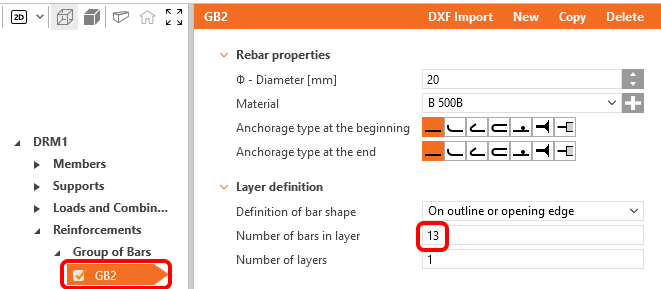
For item GB2 only change the number to 13 pcs.
Adjust the group of bars GB5 and GB6 to match the shear reinforcement in the wall.
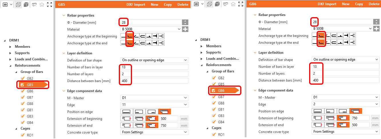
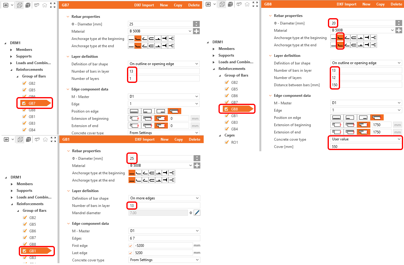
Adjust the other items GB7, GB8 and GB1 again as shown below.
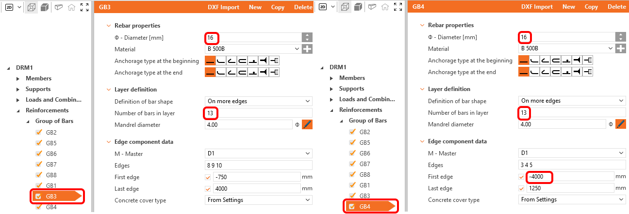
The group of bars GB3 and GB4 must also be adapted.
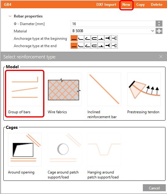
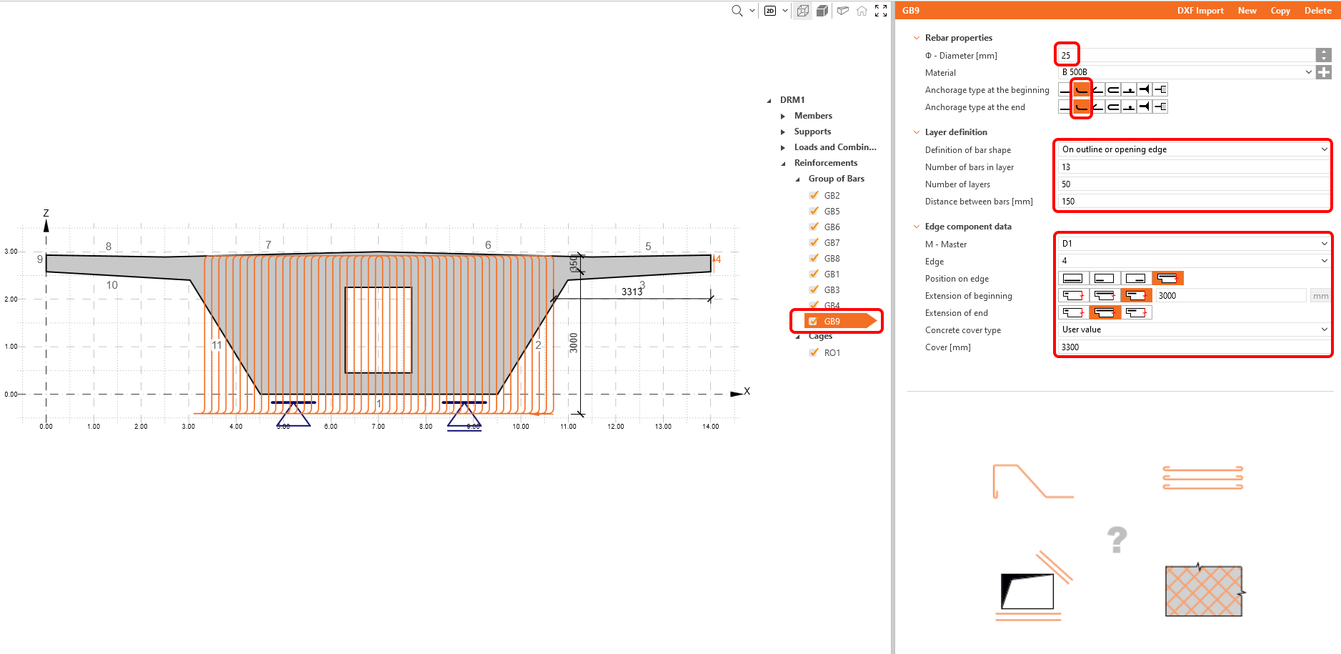
There is no vertical reinforcement specified in the diaphragm yet. So create a new Group of bars by clicking on the button New and selecting the Group of bars.
To modify a new group, first of all we have to define the Definition of the bar shape to On outline or opening edge. Fill the other cells as shown in the figure.
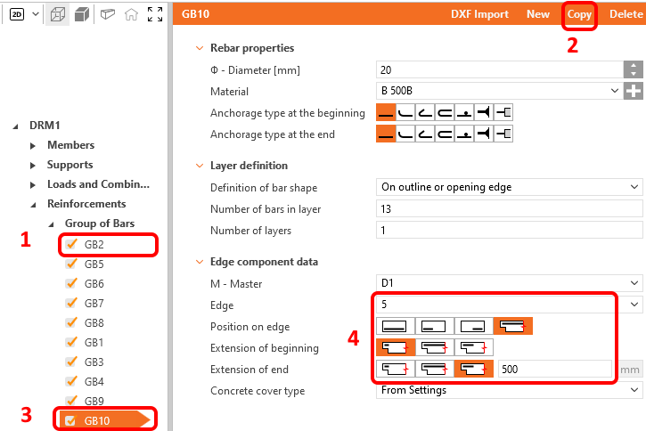
The last item that is missing in the model can be created as a copy of Group of bar GB2. Then redefine its position to the opposite cantilever.
Reinforcement is done, you can proceed to Prestress.
5 Prestress
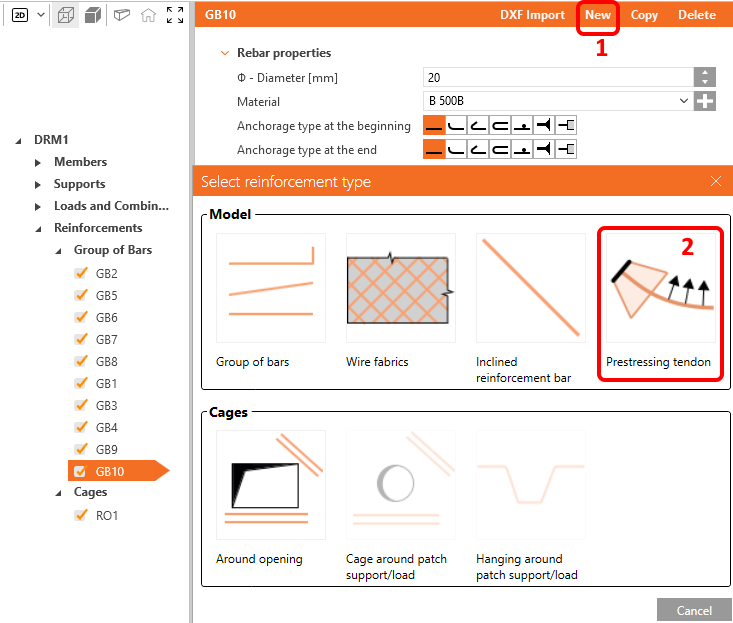
We can also add a prestressing to the diaphragm. To do this, click on the New button and select the Prestressing tendon option.
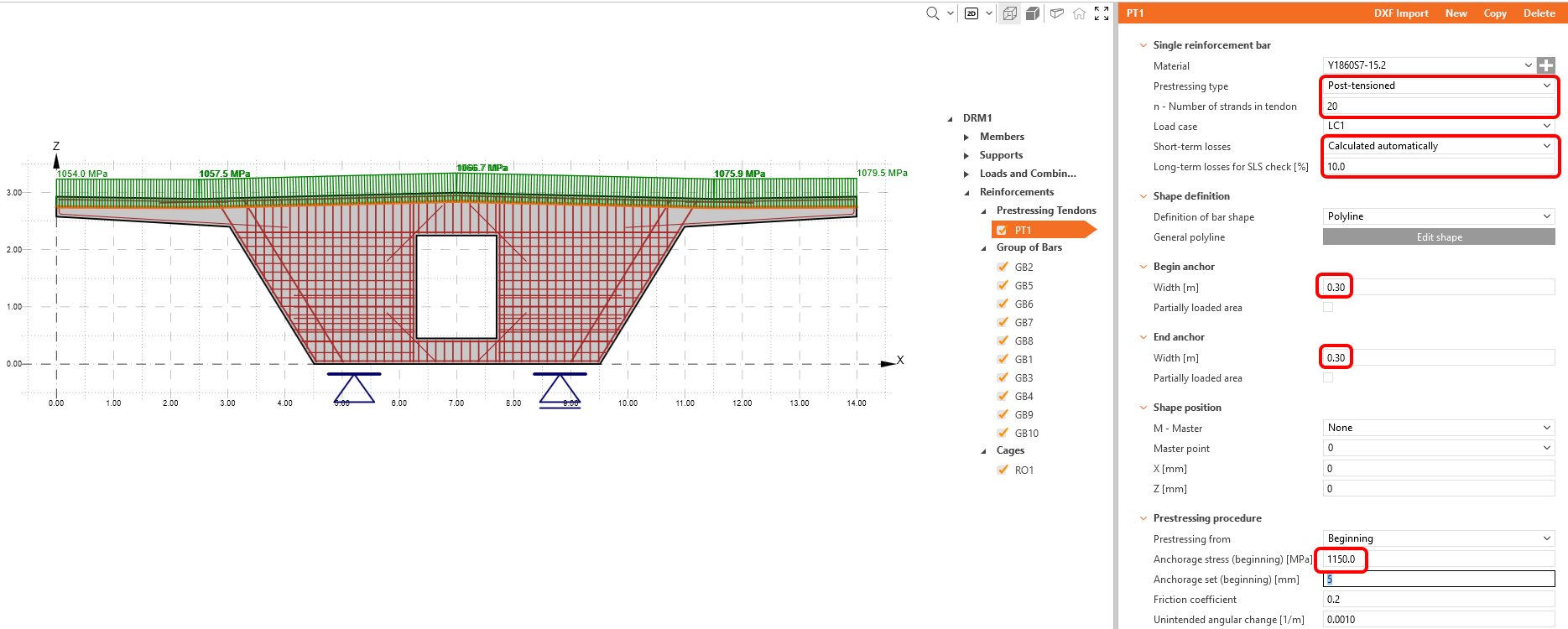
Define the tendon geometry by setting the Definition of bar shape to Polyline and using the Edit Shape button to open the dialog for entering coordinates. The coordinates can be entered, for example, by copying them from an Excel spreadsheet.
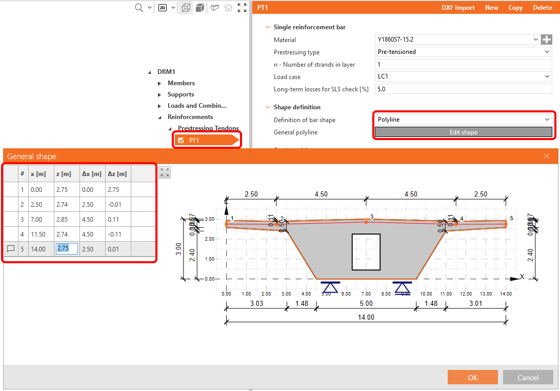
Next, just define the inputs according to the following figure. For short-term losses, choose automatic calculation.
6 Calculation and checks
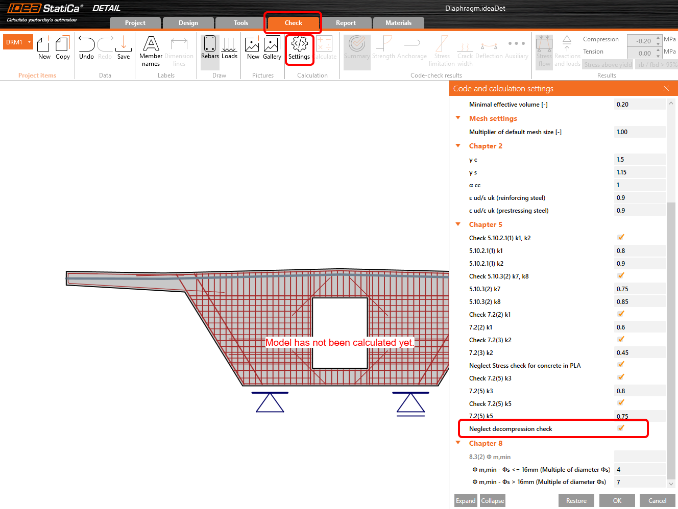
In the navigator, switch to Check. Before starting the calculation, adjust the Settings. Check the Neglect of the decompression check.
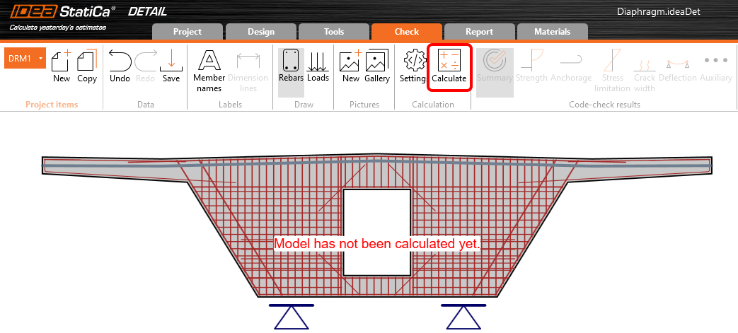
Start the calculation.
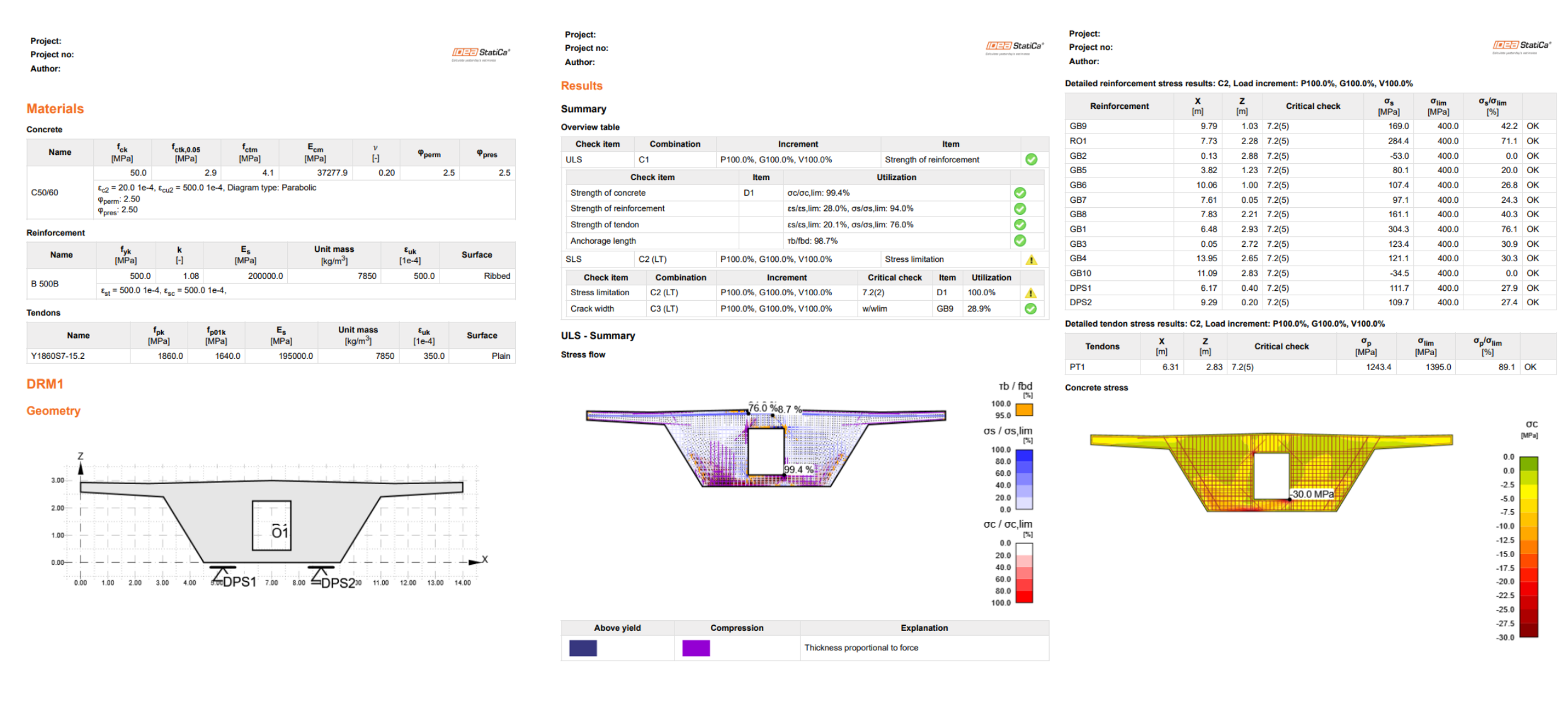
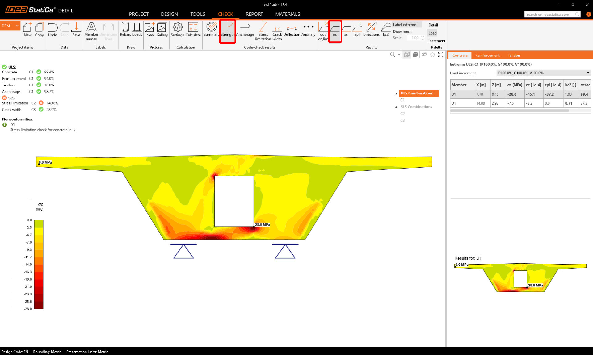
At the top left you can see an overview of all the checks, the percentage utilization and the status of the checks (pass/fail). At the top right you can find detailed calculation results and the amount of permanent and variable load applied. In the figure below the table you can see the result of the design for the ultimate limit state of the concrete.
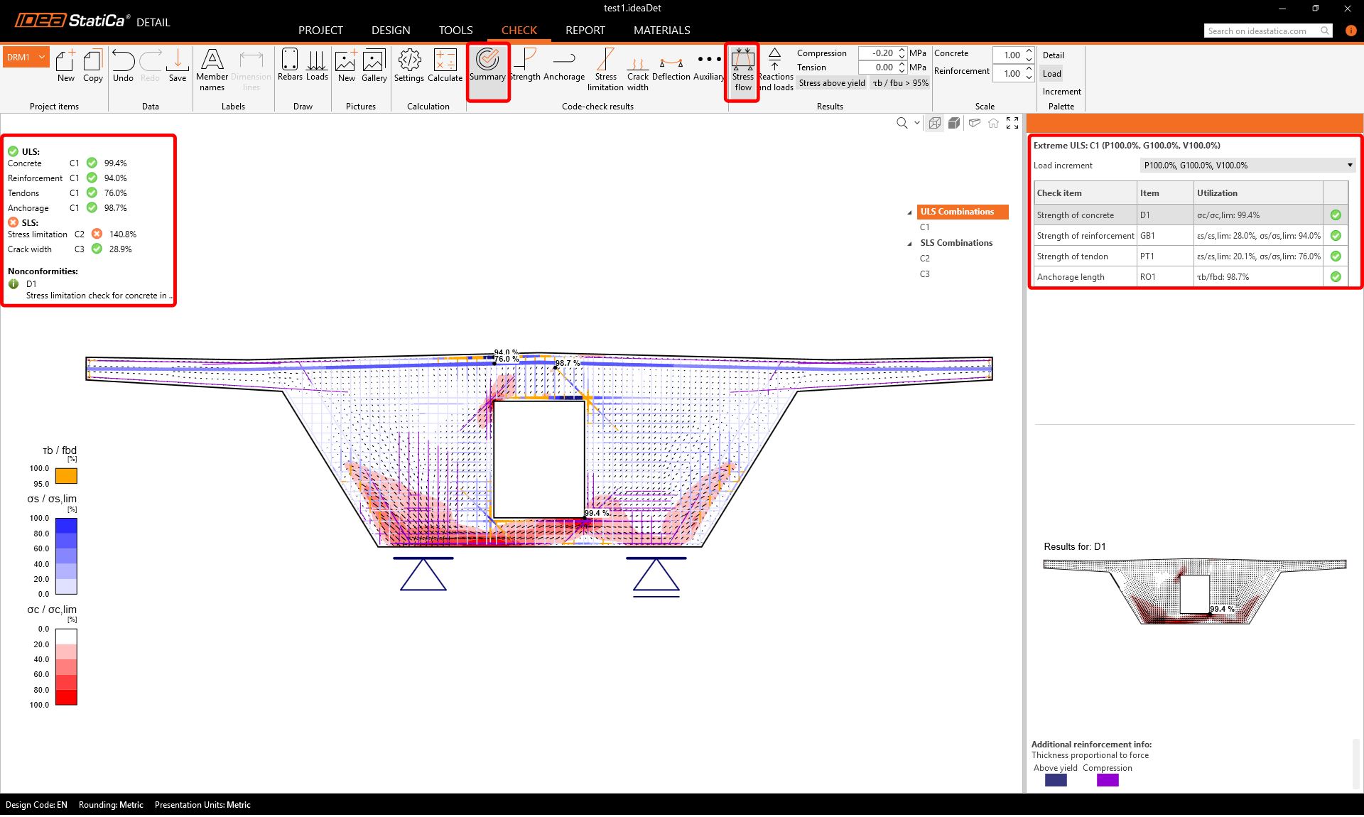
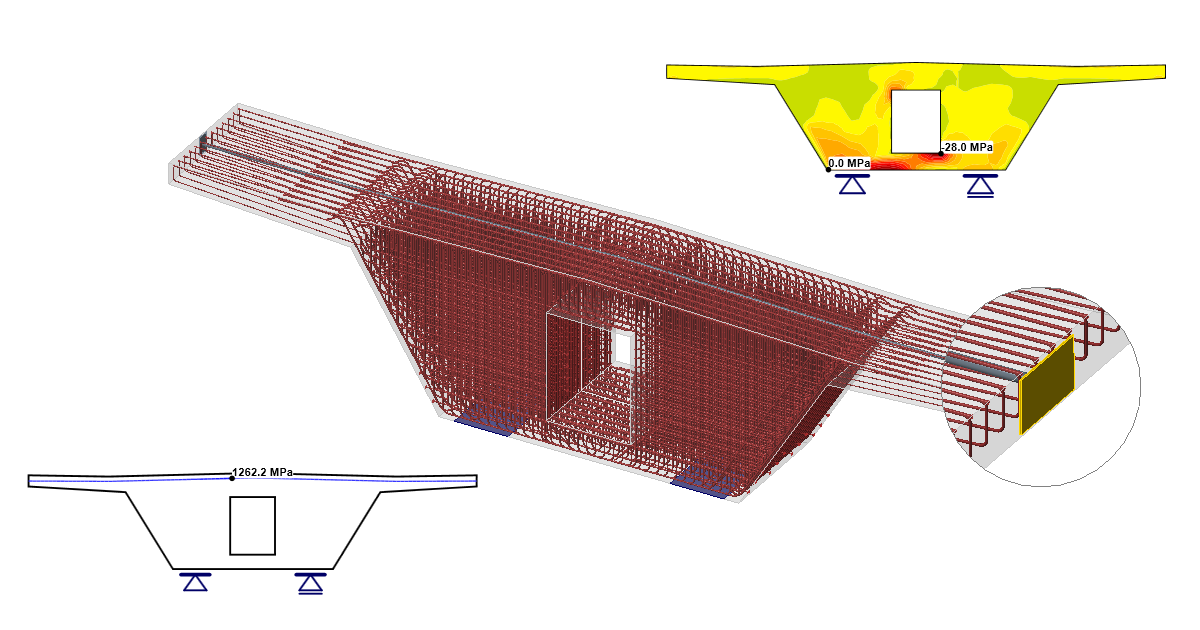
Next switch to the Strength code-checks results. Here we can see the stress check in the concrete. The calculation is non-linear and therefore takes into account the plastification of the material. It shows the stress in the concrete adjusted for the effect of the Partially Loaded Area above the support. Note also the value of the ultimate stress in the concrete, which does not correspond to the design strength of the concrete. For more information on the calculation of limit stress in concrete, see Theoretical Background.
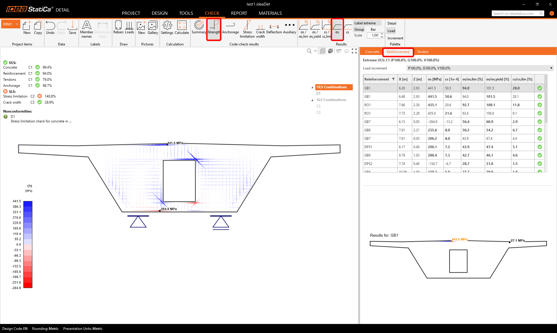
Similar results can be displayed for reinforcement. Switch to the Reinforcement tab. The options in the top ribbon will change and the detailed results in the table (stresses and strains of the individual inserts, including their total usage) will be displayed.
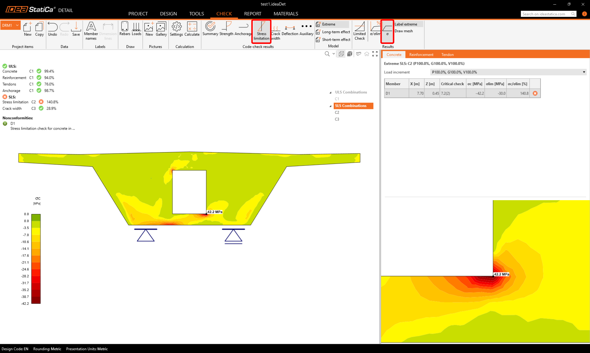
The SLS results can be found under the Stress limitation, Crack width and Deflection. Checking the Stress limitation, you will find that the stress in concrete in the bottom corner of the opening is unsatisfactory. There is a stress peak.
You can get rid of it using the Limited stress feature that can automatically neglect such a peak.
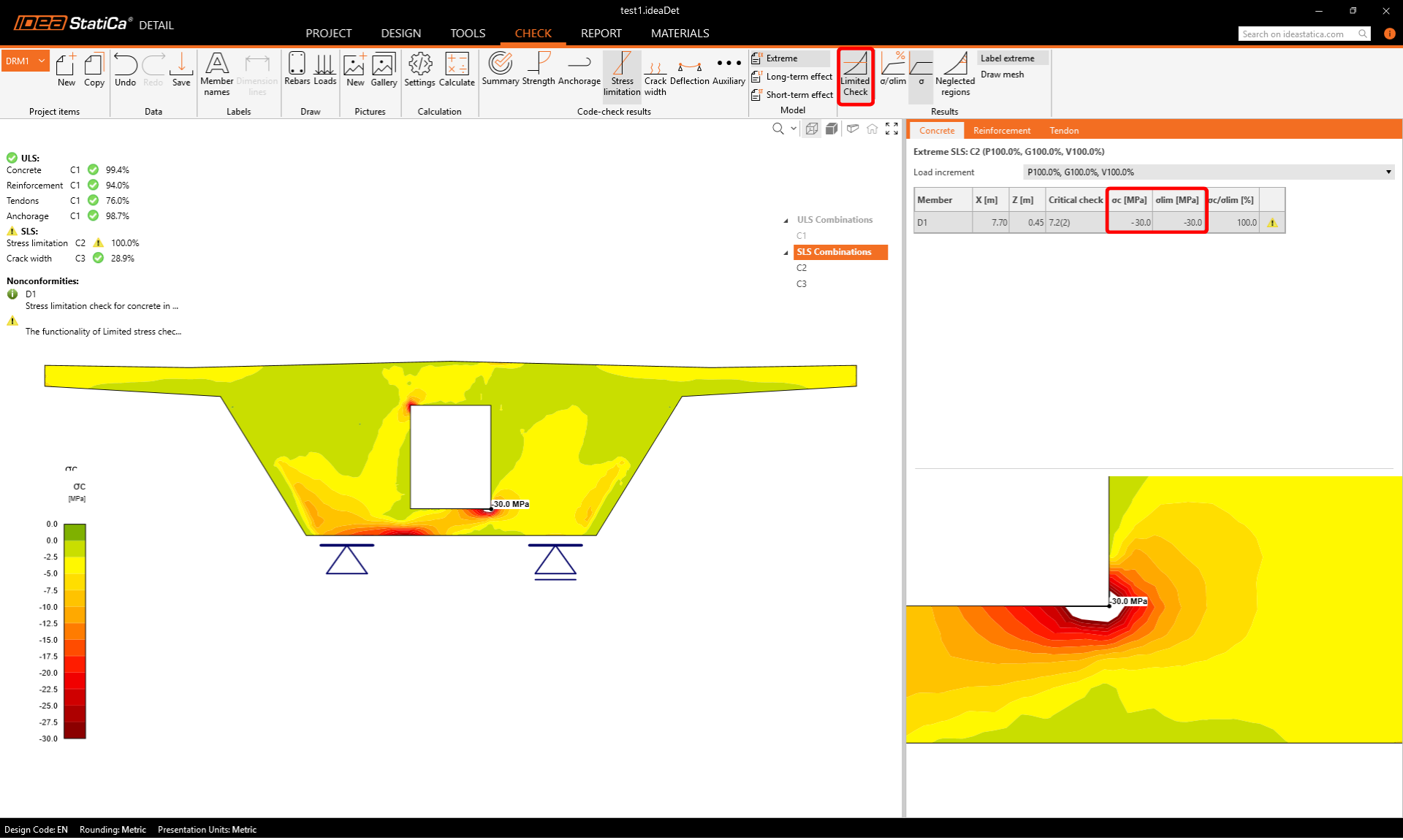
- Read more about the functionality in Limited stress check feature in Detail
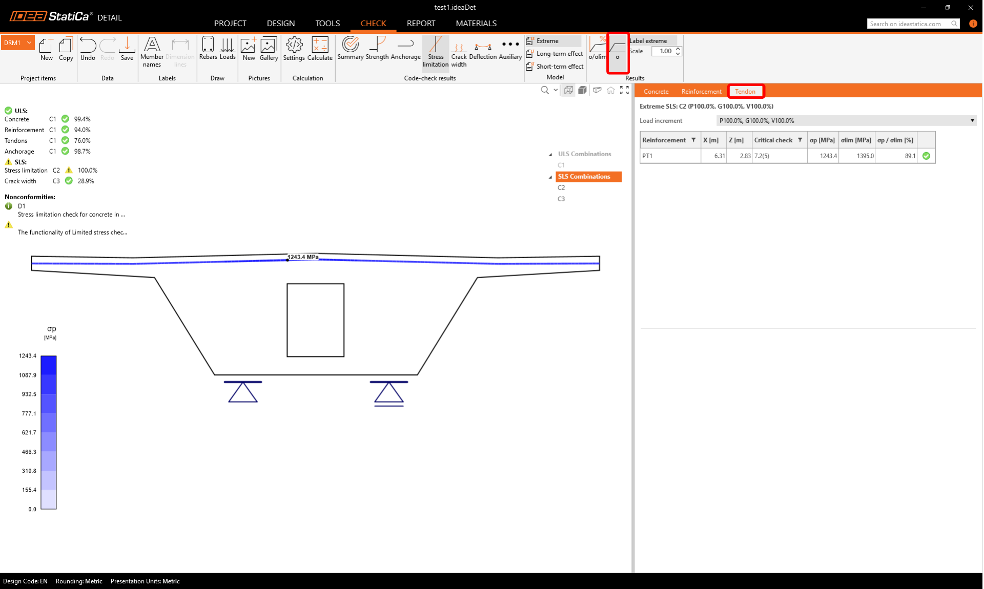
Check out the stress in the tendons, too.
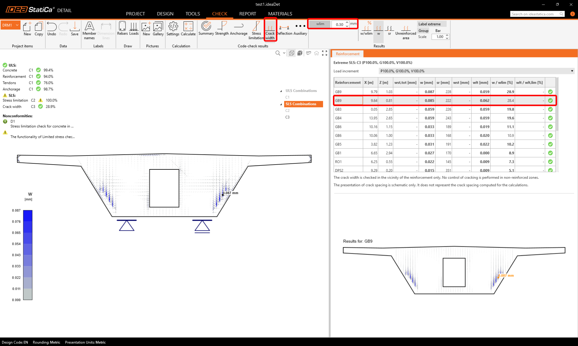
It is also possible to check the crack width including the effects of prestressing. You can display the results for individual reinforcements.
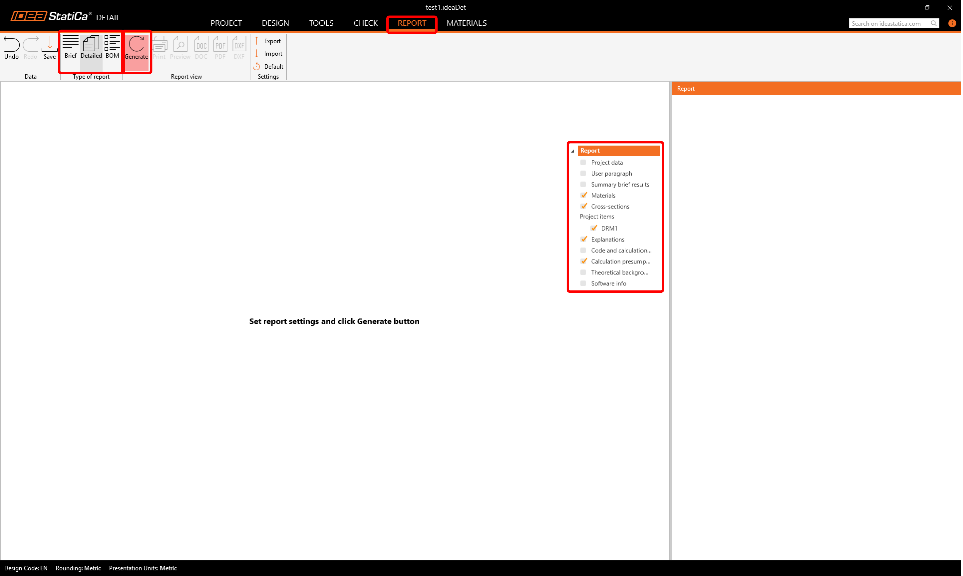
7 Report
You can also view all calculation results in the report. Just switch to the Report tab and click Generate. You can edit the content of the report or export it to DOC/PDF format using the buttons in the top ribbon.