
Development length in IDEA StatiCa Detail (Metric)
First, let's define what the development length is and what it is practically used for: ACI 318-19 uses the development length calculation to ensure the reinforcement develops the design strength at a critical section without slip. This length depends on the bar size, type, concrete strength, bar coating (such as epoxy), and confinement conditions. Development length is used to determine how far a reinforcing bar must extend into a support or spliced region to achieve full tensile or compressive capacity as designed. The requirements are specified in Chapter 25 of ACI 318-19.
In the ACI 318-19 Commentary section R.25.4.1.1 explains that "The development length concept is based on the attainable average bond stress over the length of embedment of the reinforcement."
In IDEA StatiCa Detail, the development length is not calculated explicitly, but the bond stresses and bond strength are calculated directly from the CSFM. The following article will help correlate the bond stresses and force calculation to the development length calculated with ACI 318.
Fully developed reinforcement with a hook
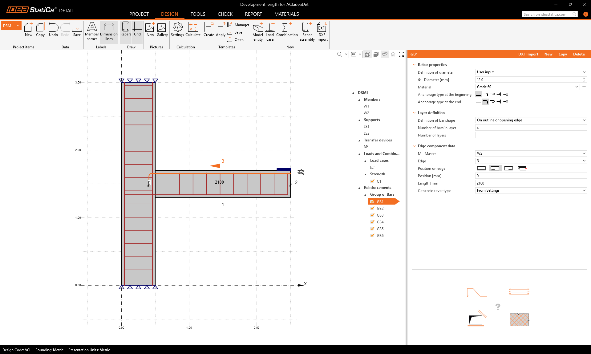
We will explain how exactly development length works in the IDEA StatiCa Detail application using this simple example. We will examine a selected reinforcement of a horizontal beam that is terminated in a column.
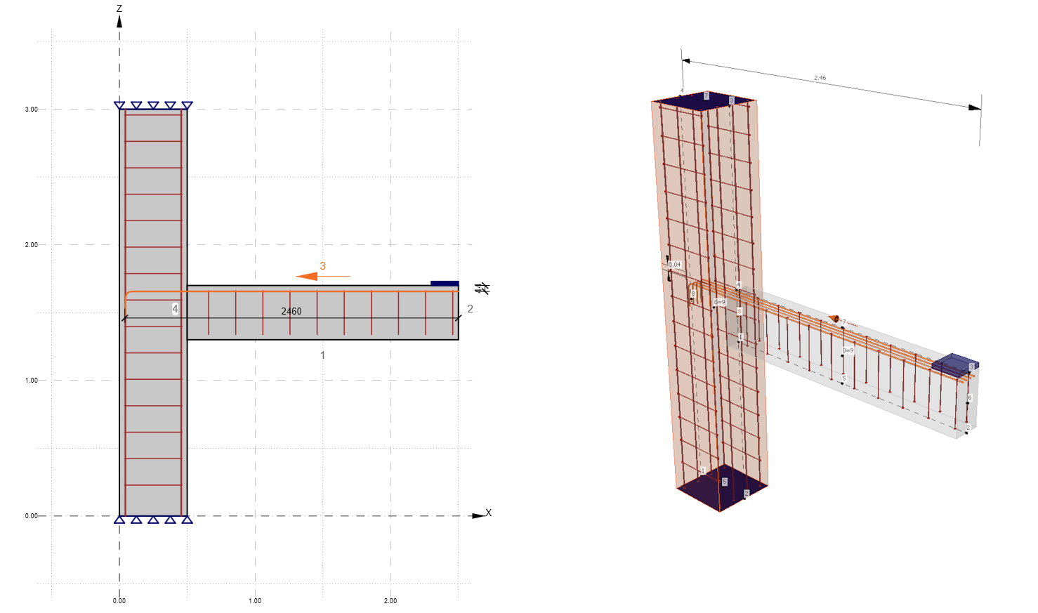
The horizontal beam has a rectangular cross-section with dimensions 400 x 200 mm. The reinforcement under consideration is 4 bars of 12 mm diameter. The strength of concrete and steel, with other input parameters, is shown in the following figure.
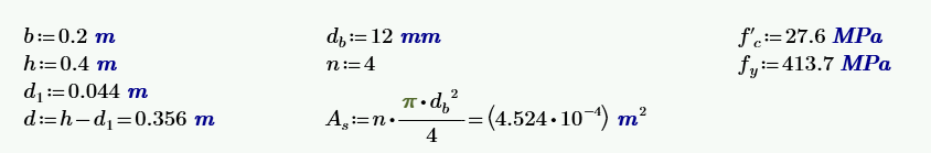
From the figure, it can be estimated with certainty that the reinforcement will be fully developed in the critical section of the beam. However, let's verify this. For the standard hook, the calculation in ACI 318-19 Section 25.4.3.1 should be used.
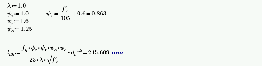
The values of the ψ factors are taken from ACI 318-19 Table 25.4.3.2, with the least favourable value taken for ψr and ψo. We consider this because the Detail application cannot determine these factors directly. The model is therefore set up as if these two factors were always the least favorable. This will be further discussed later in the article.
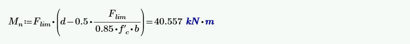
Now let's see what the moment capacity of the critical section of the beam should be. We calculate it using a simple formula:

In the Detail application, we loaded the cantilever beam with a force of 50 kN, which is 1.9 m away from the critical section. From the results, we can see that the model is only able to carry 68.9% of the specified load; it means that the maximum applicable force is 0.689 x 50 = 34.5 kN. The moment capacity determined by the Detail application is therefore Mn = 34.5 x 1.9 = 65.5 kNm.
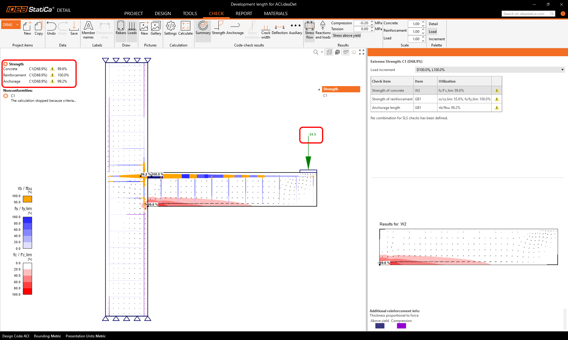
The slightly increased load capacity is due to a more accurate calculation of the compression zone at the lower surface of the beam, and thus the distance of the resultant compression and tension forces is slightly greater than based on the formula calculation.
It is also important that the ϕ factors, according to ACI 318 Chapter 21, are and will be considered later in the article with a value of ϕ = 1.0.
Partially developed reinforcement with a hook
We have now described a generally unambiguous situation and verified the calculation when it is clear that the reinforcement is fully developed. But what if the situation is borderline? Or will the development length be insufficient? In the following, we will show how the IDEA StaciCa Detail application can handle such a situation.
From the previous calculation, we know that the ldh, according to ACI 318-19 section 25.4.3.1, is approximately 245 mm. In the following example, we will therefore place the hook at a distance of less than 245 mm, namely 100 mm.
After calculating the model, we can see a significant decrease in load capacity. The model is able to carry only 43.8% of the load, which means that Mn = 21.9 x 1.9 = 41.6 kNm.
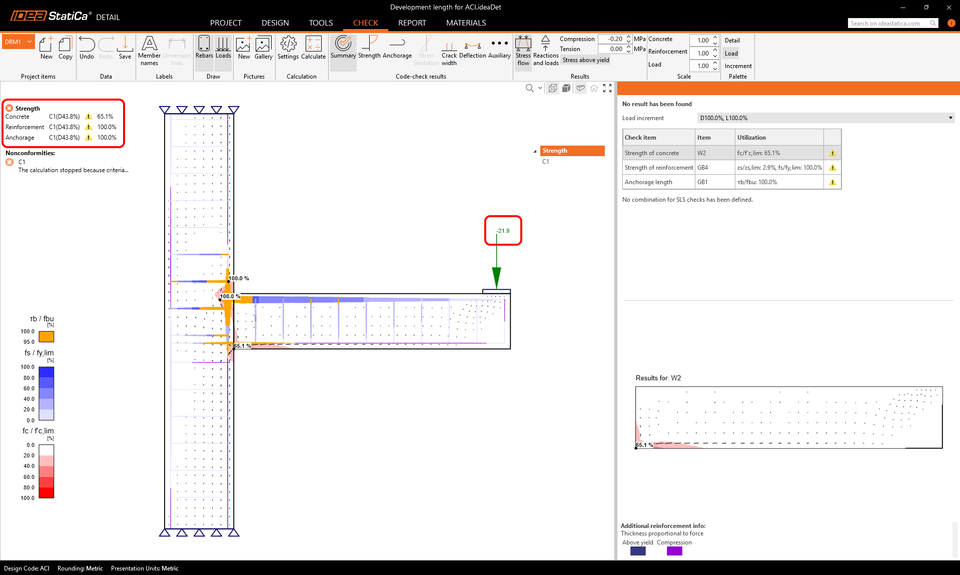
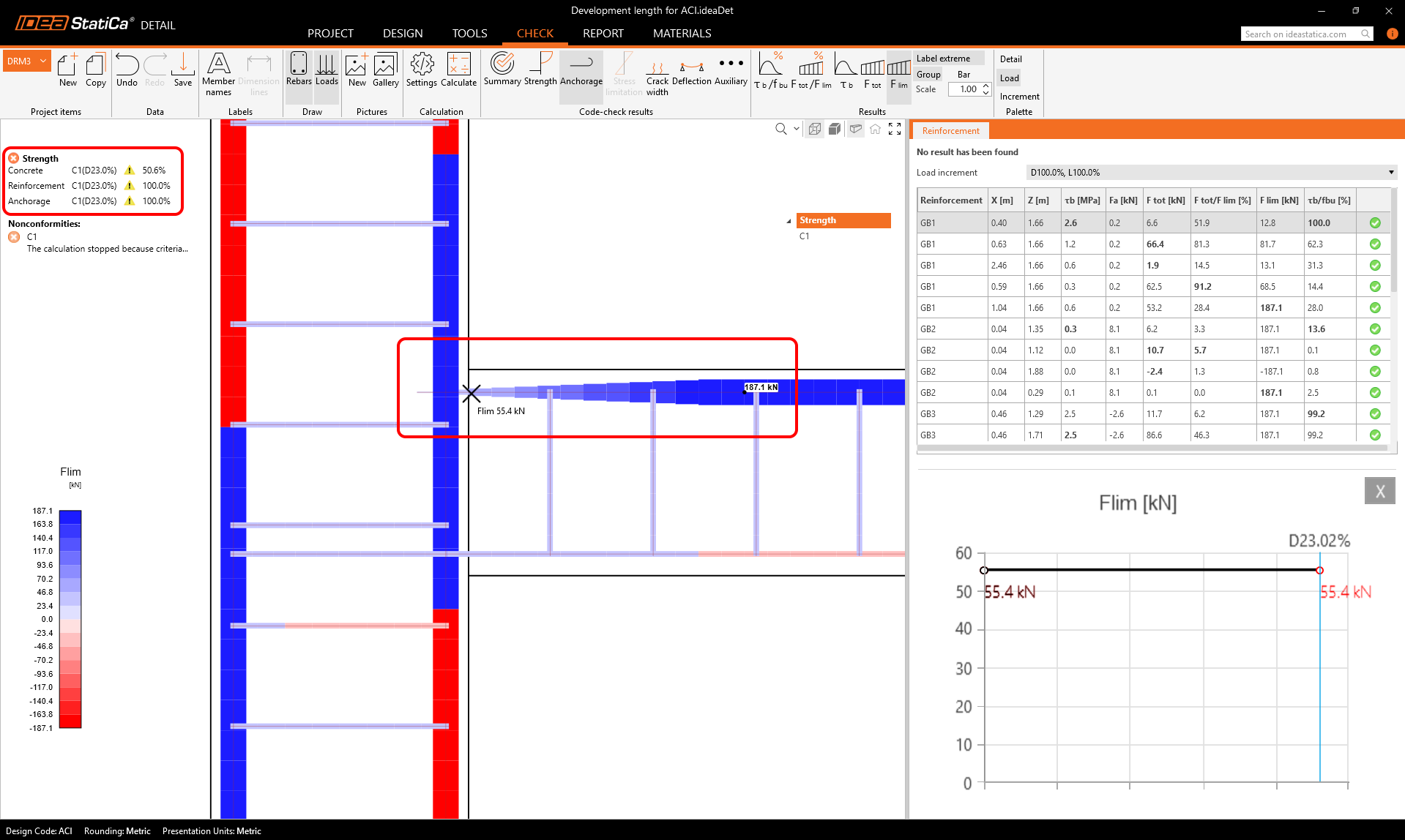
This is obviously due to the fact that the reinforcement is not fully developed at the critical section. Now the question is where to display the development length for each reinforcement in the application. If we look in the Anchorage tab, we find the Flim variable in the ribbon.
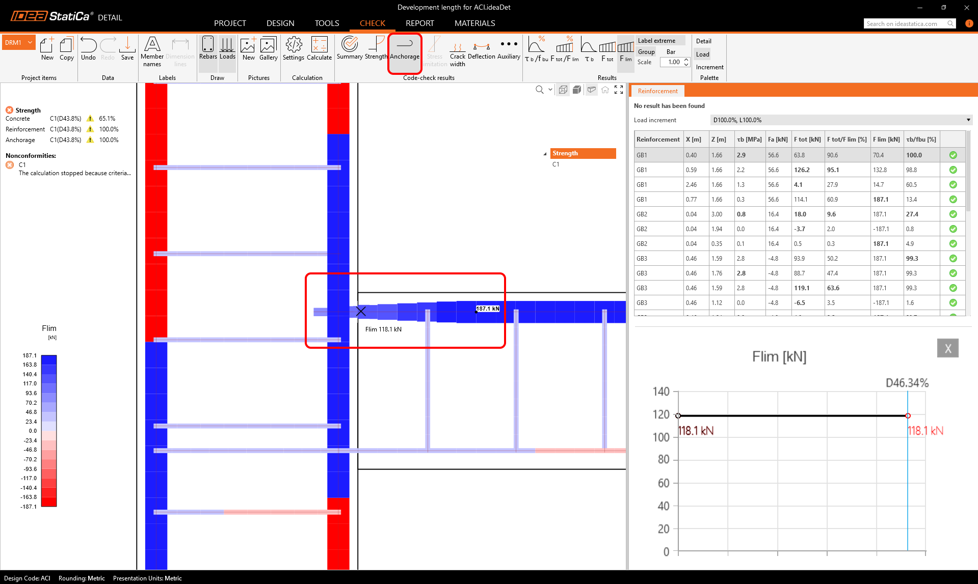
Flim is the limit (maximum) force that can be transferred by the reinforcement at a specific point. In the figure, we can observe how it gradually develops up to the maximum value, which corresponds to the value As x fy. The distance from the end of the reinforcement to the maximum value of Flim is therefore the development length. If we measure this distance directly in the model, we get approximately 250 mm for this case (we can derive from the number of finite elements, knowing that the reinforcement is embedded 100 mm into the column, which corresponds to 3 finite elements). The development length ldh calculated according to 25.4.3.1, is approximately 245 mm. So we have a good match.
Please note that the hook is not directly modelled by finite elements in the application, but is inserted into the model as a special spring to ensure correct development of the Flim value. This is also the reason why it is not rendered in the results above.
We can also see that the Flim at the critical section is 118.1 kN. If we replace the As x fy items with Flim in the formula for calculating Mn, we get the theoretical moment capacity, which corresponds to the result from the application.
Partially developed reinforcement with a straight end
In the previous examples, the reinforcement was always ended with a 90° hook. Now we will show what the situation looks like if the reinforcement is terminated without a hook (straight end). In this case, the development length is calculated according to ACI 318-19 section 25.4.2.3. In the Detail application, we left the embedded length at 100 mm, and the situation looks like this:
The development length has rapidly increased to more than double the value, the load capacity of the model has dropped to approximately half of the model with the hook, and to less than a third of the model with fully developed reinforcement.
We can also observe that the initial value of Flim is approximately 30% of the maximum value for the hook model and logically 0% for the free end model.
Conclusion (Summary of Key Practical Principles):
The article demonstrates how development length, as defined in ACI 318-19, is practically implemented and visualized in IDEA StatiCa Detail. Development length is the necessary embedment length of reinforcement to achieve its full strength without slip, and it depends on several factors such as bar geometry, concrete strength, and anchorage type. The software models this behavior using the Flim variable, which shows how the force develops along the rebar. Users can directly verify whether reinforcement is fully developed by comparing the embedment length with the required development length, derived from ACI provisions. Practical examples in the article show that insufficient development (e.g., shorter embedment or absence of a hook) significantly reduces the load capacity, which is accurately reflected in the software results. Thus, IDEA StatiCa Detail allows engineers to validate anchorage efficiency and optimize rebar design based on real behavior, improving safety and code compliance.
The development length modelling is directly based on bond strength. The theoretical background provides a description of the implementation.
The explanation given in this article applies to both 2D and 3D Detail model types.