
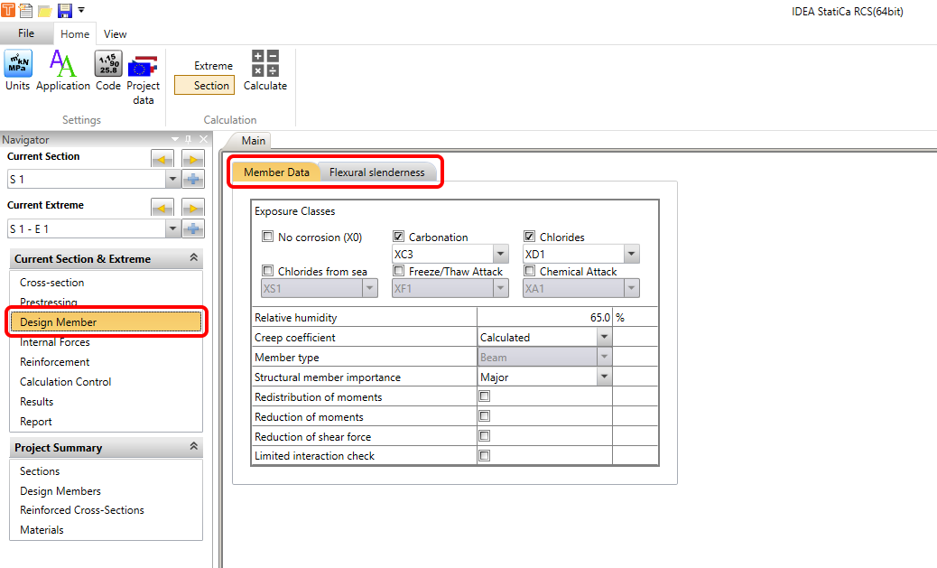
After creating a cross-section in the RCS application, it is necessary to set data in Design Member. In Design Member, you can find two tabs of the settings.
- Member Data
- Flexural slenderness
Let's focus on the first tab:
Member Data
Go to the Navigator -> Design member -> Member Data. You will find a part dedicated to the environment (Exposure Classes, Relative Humidity) and other settings (Creep coefficient and Structural member importance) common for all member types (Beam, One-way slab, Compression Member). The rest of the tab is available only for Beam and One-way slab, and it allows us to tick/untick checkboxes for the reductions and redistribution. See the detailed picture below.
Now we'll go through the options. In the beginning, you need to set properties group Exposure Classes. This setting affects the calculation of minimum reinforcement and crack width control according to EN 1992-1-1.
You can set the following conditions:
- No corrosion – switch on/off exposure class with no risk of corrosion or attack X0. This class is usually prescribed for plain concrete.
- Carbonation – select exposure class XC for corrosion caused by carbonation.
- Chlorides – select exposure class XD for corrosion caused by chlorides.
- Chlorides from the sea – select exposure class XS for corrosion caused by chlorides from the sea.
- Freeze/Thaw attack – select exposure class XF for corrosion caused by freeze/thaw cycles.
- Chemical attack – select exposure class XA for corrosion caused by a chemically aggressive environment.
- Relative humidity – input value of relative humidity.
As next, you can choose if the Creep coefficient is calculated automatically (Calculated) or if the value of the creep coefficient Φinf is defined by the user (User input). See the explanation of how it will affect the results in the SLS results in RCS - Stress Limitation, Crack Width, Detailing.
In the end, you need to select the type of Structural member importance. Minimum reinforcement may be omitted in members of minor importance (e.g., lintels with a span of 2 m), which do not contribute significantly to the overall resistance and stability of the structure (EN 1992-1-1, art. 6.2.1(4)).
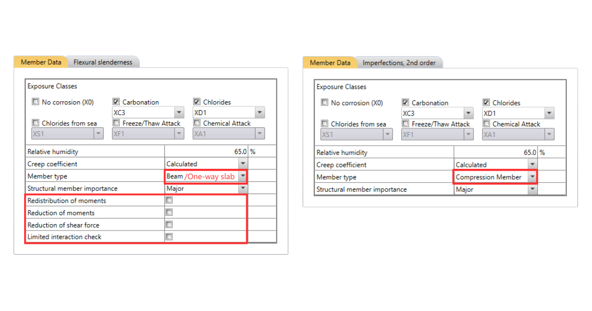
The rest of the tab differs according to the type of the design member. For Beam and One-way, the options to switch on/off Redistributions and reductions are available.
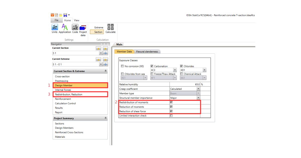
Please note that enabling redistribution and reduction will cause a new bar to appear in the Navigator.
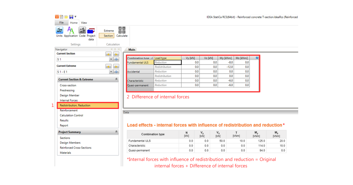
Here you have to manually enter the difference of internal forces obtained from the calculation according to Eurocode. The software will then automatically recalculate the internal forces by the entered values.
How to obtain the particular differences, see the articles mentioned below:
- Redistribution of moments – moments redistribution according to EN 1992-1-1, art. 5.5
- Reduction of moments – reduced moments in supports according to EN 1992-1-1, art. 5.3.2.2(3) a 5.3.2.2(4)
- Reduction of shear force – a reduced shear force for members with loads near supports according to EN 1992-1-1, art. 6.2.2(6) and 6.2.3(8)
The last option relates to the interaction:
- Limited interaction check – switch on/off the limitation of interaction check in the distance less than d from a position of the maximal moment according to EN 1992-1-1 6.2.3(7). You can find more about interaction check in the article about ULS checks.
Flexural Slenderness and Imperfections, 2nd order
The second tab differs according to the type of design member. For a Beam and One-way slab, you need to set the parameters for Flexural Slenderness.
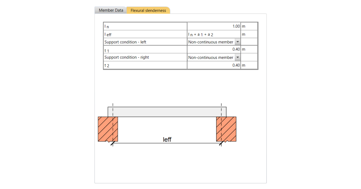
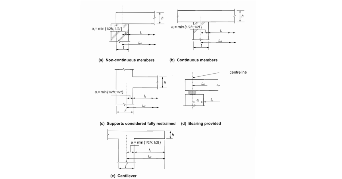
The software will calculate the effective length of member leff for you. All you need to do is to set a clear distance between the faces of supports ln, set support conditions (see the figure below), and set the width ti of the supporting element.
Then the effective span is calculated as
leff = ln + a1 + a2
where ai is determined according to EN 1992-1-1 art. 5.3.2.2(1).
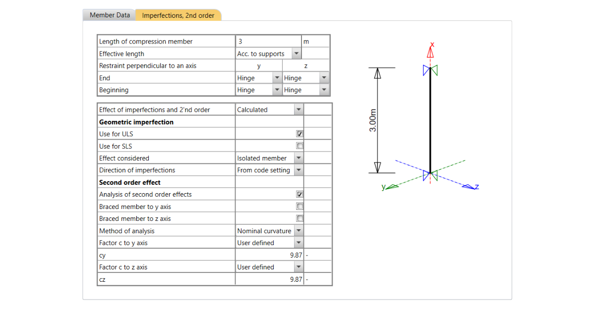
For Compression Member, the different tab appears, and you need to set the parameters for Imperfections and 2nd order. These setting options are explained separately in the article Second-order effect in RCS application.
Get 14 days of full access, completely free.
Check out IDEA StatiCa for free