Code checking of a box girder diaphragm according to Eurocode
The behavior of concrete box girder diaphragms depends on many factors, such as the placement of the bearings, the inclination of the sidewall of the box girder cross-section, the global static scheme of the structure, and many more. The design is based on the analytical method strut and tie, mentioned in the Eurocodes. This method is very simplified and cannot check the details for the serviceability limit state. The goal of the article is to introduce the differences between the S&T method and physically non-linear solution based on the finite element computation of the wall model. The advanced method CSFM (compatible stress field method) allows the calculation and code-check of the crack width, stress limitation and deflection for short-term and long-term effects.
Description of the model
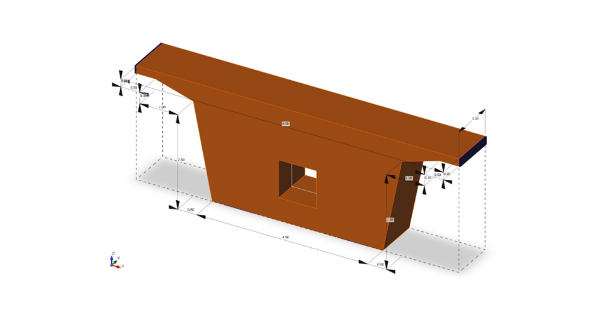
The analysis is performed on a box-girder bridge with spans 40 x 45 x 40 m. The height of the diaphragm is 3 m, its width is 8.5 m and its thickness is 1.2 m. The diaphragm is indirectly supported on 0.8 m wide bearings, which are represented in the model by bearing plates (fig.1). The model is loaded with self-weight, superimposed dead load, secondary effect of the longitudinal prestressing, and traffic load LM1.
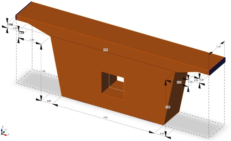
Fig.1 - Geometry of diaphragm
Assumptions of the strut and tie method
Generally, the strut and tie method provides an efficient tool for the check of concrete structures, in which there are so called discontinuity regions. Principally, the strut and tie model is created using linear analysis and the direction of principal stresses from the applied loads. The model consists from struts, nodes and ties, which are subsequently checked. We must fulfill all the requirements such as detailing and anchorage length of reinforcement. Due to the fact that the method is based on the theory of concrete plasticity and lower bound theorem, it is necessary to achieve the equilibrium conditions between external and internal forces and to not exceed the design strength of materials. The method is based on the assumption that the rupture of the reinforcements happens before the crushing or brittle failure of concrete. The danger of this method is that the conditions of compatibility of deformations and sufficient ductility of the structure is not fulfilled and must be ensured in another way. Due to these restraints, it is necessary to obey the rules according to [1].
Topology of the strut and tie
The design of our model uses the result calculated by topology optimization [2], which is based on the energy principle to find the material distribution with a minimal potential energy. This approach determines directly the shape and helps correctly create the model of strut and tie analogy. To create a topology that catches the effects of shear and torsion on the diaphragm, two models were made which create one complex model for design of reinforcement and to check the nodes. First model covers the effect of shear with the analogy consisting of struts and ties (fig.2a). The model serves for the design of reinforcements in the vicinity of the upper part of the diaphragm, where the biggest tensile strains are located. The second model serves for covering of the torsion effect, where the triangle strut and tie shape was developed (fig.2b).
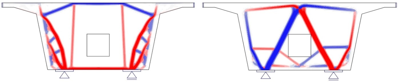
Fig.2 - (a) Model of topology optimization for shear effect; (b) Model of topology optimization for torsion effect
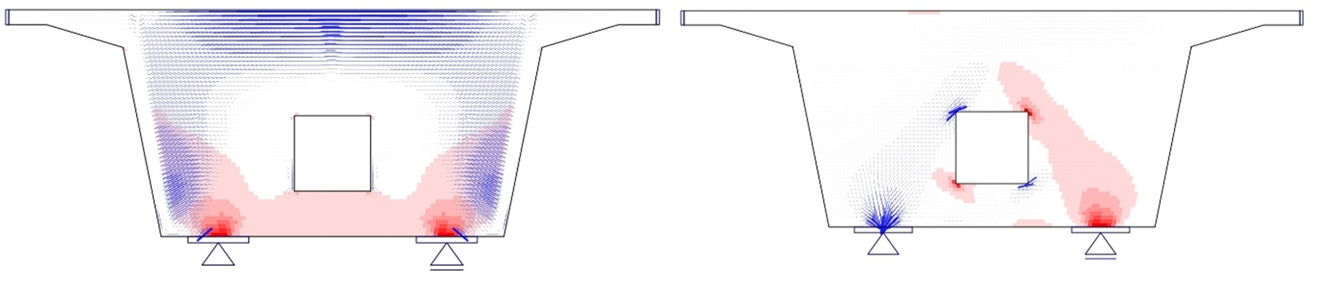
Fig.3 - (a) Model of linear analysis for shear effect; (b) Model of linear analysis for torsion effect
Results of strut and tie method
Models in the program Midas Civil (fig.4) were loaded with extreme loads. The required reinforcements were designed from the tensile forces and the areas of the nodes were checked according to [1]. The extreme value of stress appeared on the node (fig.2a) under the right bearing, where the compression stress reached σed = -10,1MPa [Tab.1].
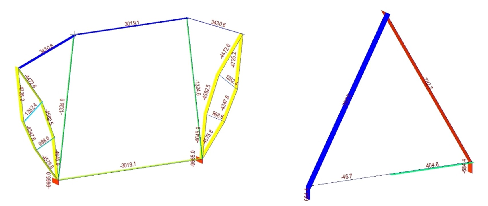
Fig.4 - (a) Axial internal forces on the 1D model for shear effect; (b) Axial internal forces on the 1D model for torsion effect

Tab.1 - Extreme utilization in compression according to strut and tie method
Method CSFM
The new method CSFM (Continuous Stress Field Method) eliminates the shortcomings and simplifications of the strut and tie analogy. The ductility of the structure, finding the correct geometry of strut and tie analogy, all the iterative processes are no longer necessary, because the models are solved using FEA powered by CSFM. The assumptions of non-linear analysis are based on fictitious rotating cracks, where stress free cracks are considered without slip of reinforcement. The equilibrium in the cracks is considered together with average stress in the reinforcement bars. Concrete is neglected in tension but the effect of tension stiffening of the rebars is considered. These assumptions allow to calculate cracks and the diaphragm can be checked for serviceability limit state [3].
Loading of the diaphragm
Loads are transferred into the diaphragm through the wall of the box-girder cross-section. Almost the entire shear is transferred through the sidewall of the box-girder cross-section (fig.5a). The torsion is transferred through shear flow into the volume of the diaphragm (fig.5b).
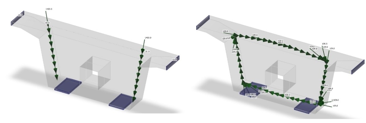
Fig.5 – (a) Shear loads model; (b) Torsion loads model
Comparison of S&T and CSFM method
The comparison of results is possible only for ultimate limit state, where the extreme stress in concrete (fig.6a) was compared with the limit values. The comparison was performed also for reinforcements where the strains were also checked. They have lower values in comparison to the bilinear diagram of naked steel due to the effect of tension stiffening [3]. Stresses and strains were compared with the limit values for design yield stress in the rebars (Tab.2)
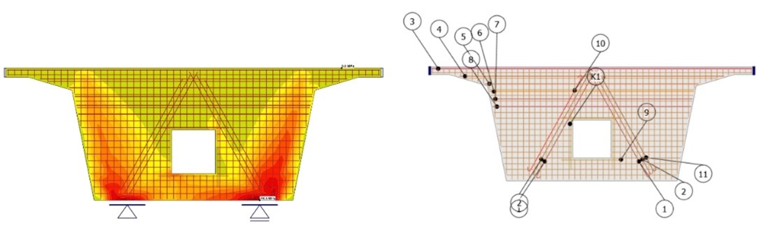
Fig.6 –(a) Principal stress in concrete; (b) Reinforcement/indication of rebars
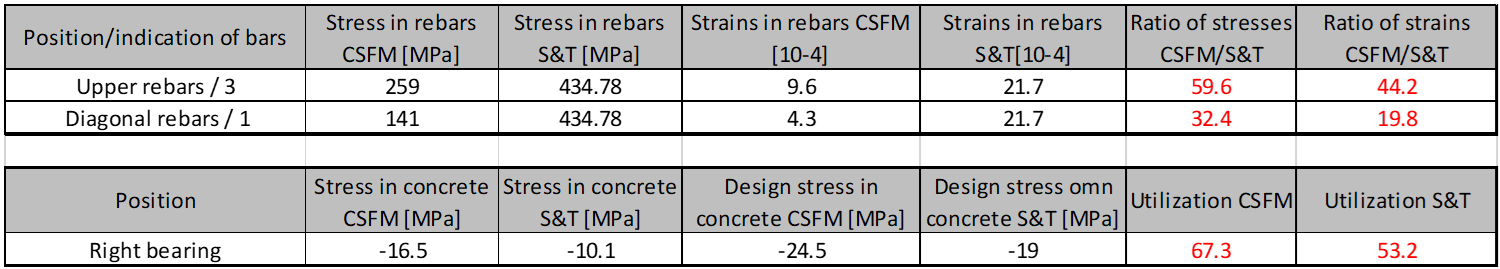
Tab.2 – Comparison of S&T and CSFM stresses in concrete and reinforcement
Results of the analysis proved that the stresses of designed rebars are lower than the considered design yield stress in strut and tie method. For rebars placed in the vicinity of the upper part in the diaphragm the stresses were approximately 60 % of the design yield stress. There were larger differences for the diagonal rebars designed from the torsion model (fig.4b). Results of non-linear analysis proved utilization 30 % of design yield stress. Extreme stresses appeared on the wire fabrics (fig.7a) due to transverse tensions in the struts (fig.4a). The governing check of reinforcement was for the bond stress (anchorage length) nearby bearing (fig.7b).
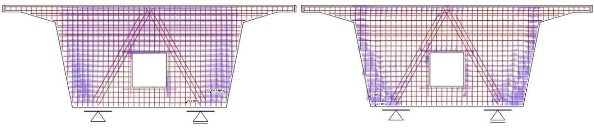
Fig.7 – (a) Maximal stress in reinforcement; (b) Maximal bond stress in reinforcement
Serviceability limit state
Given the fact that the strut and tie method, being a plasticity method, cannot calculate crack widths, stress limitations and deflections, we cannot perform a comparison between CSFM and S&T. Results of serviceability limit state represent the behavior of the diaphragm during regular traffic. Crack widths are very important during the lifetime of structures and especially regions of discontinuities. They significantly influence the lifetime of the whole structure mainly because of the corrosion of reinforcements. Two combinations were created for the model of the diaphragm for crack width check. First quasi-permanent combination does not take into account the effect of traffic (LM1) as opposed to the second one – a frequent combination, which considers this effect. Eurocode prescribes that code-check of crack width for reinforced members should be performed for a quasi-permanent combination (fig.8a). The second combination was created to research the behavior of the diaphragm with the effect of traffic (fig.8b).
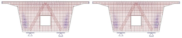
Fig.8 – (a) Cracks for quasi-permanent combination; (b) Cracks for frequent combination
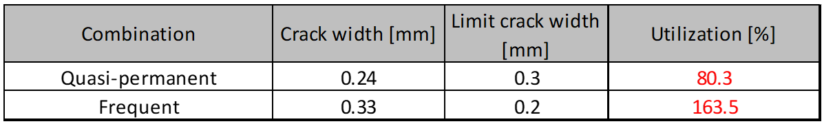
Tab.3 – Comparison of crack width for quasi and frequent combination
Maximal crack width is in the area of transverse strains in the struts leading from the bearings. It is evident that the cracks are more inclined due to the effect of torsion shear flow from traffic than only from shear flow in the sidewall.
Conclusion
The strut and tie method is a really efficient tool in the hands of structural engineers and offers in comparison with non-linear calculation in application IDEA StatiCa Detail using CSFM method a safe design of the diaphragm box-girder bridge for ultimate limit state. Non-linear analysis proved that tension in the rebars at the upper surface of the diaphragm was at 60 % of its capacity (design yield stress used in the strut and tie method) and the diagonal reinforcement was only at 30 %. Of course, lower utilization is caused by the wire-fabrics which contribute to the complex bearing capacity of reinforcement. The wire fabric is required due to detailing and was not considered in strut and tie method. It’s evident that the S&T method provides a safe design when fulfilling the reinforcement requirements such as detailing according to [1]. Due to the right topology od truss analogy which was based on topology optimization, [2] the location of maximal stress in the concrete was the same for both methods. The differences between checks in the concrete according to S&T and CSFM were approximately 13 %, where the higher utilization was obtained from the non-linear solution. From the serviceability limit state point of view, the crack widths were compared using the CSFM method, where for quasi-permanent loads they passed the check with 80 %. Frequent combination did not pass the check due to the effect of traffic load with 163 % using the limit value of 0.2 mm. Globally, it can be said that the design using S&T for a diaphragm of a box-girder bridge passes the conditions of ultimate limit state and in this case also serviceability limit state for the quasi-permanent combination. It is important to realize that the serviceability limit state cannot be covered by S&T and it is necessary to solve it by another method, in our case by CSFM (Continuous Stress Field Method).
References
[1] EN 1992-1-1 Eurocode, Design of Concrete Structures – Part 1: General rules and rules for buildings, European Committee for Standardization, December 2004-2016
[2] Mata-Falcón, J., Tran, D., T., Kaufmann, W., NAVRÁTIL, J. Computer-aided stress field analysis of discontinuity concrete regions, In: Proceedings of EURO-C 2018 Computational Modelling of Concrete and Concrete Structures, Austria, 2018, in print
[3] KABELÁČ J., ČÍHAL M., KONEČNÝ M., JUŘÍČEK L., VALÍČEK J. Serviceability limit state in discontinuity regions, In Sborník ke konferenci 25. Betonářské dny 2018, Czech Republic,ČBS